EP0352584B1 - Refouloir de projectiles pour artillerie - Google Patents
Refouloir de projectiles pour artillerie Download PDFInfo
- Publication number
- EP0352584B1 EP0352584B1 EP89113036A EP89113036A EP0352584B1 EP 0352584 B1 EP0352584 B1 EP 0352584B1 EP 89113036 A EP89113036 A EP 89113036A EP 89113036 A EP89113036 A EP 89113036A EP 0352584 B1 EP0352584 B1 EP 0352584B1
- Authority
- EP
- European Patent Office
- Prior art keywords
- carriage
- projectile
- piston
- shock absorber
- cylinder drive
- Prior art date
- Legal status (The legal status is an assumption and is not a legal conclusion. Google has not performed a legal analysis and makes no representation as to the accuracy of the status listed.)
- Expired - Lifetime
Links
Images

Classifications
-
- F—MECHANICAL ENGINEERING; LIGHTING; HEATING; WEAPONS; BLASTING
- F41—WEAPONS
- F41A—FUNCTIONAL FEATURES OR DETAILS COMMON TO BOTH SMALLARMS AND ORDNANCE, e.g. CANNONS; MOUNTINGS FOR SMALLARMS OR ORDNANCE
- F41A9/00—Feeding or loading of ammunition; Magazines; Guiding means for the extracting of cartridges
- F41A9/38—Loading arrangements, i.e. for bringing the ammunition into the firing position
- F41A9/39—Ramming arrangements
- F41A9/42—Rammers separate from breech-block
Definitions
- the invention relates to a projectile rifle for artillery with the features from the preamble of patent claim 1.
- a problem that occurs with such free-flight launchers is that, on the one hand, a high acceleration of the sled-projectile system is necessary to achieve the highest possible attachment speed and, on the other hand, the direction in which the projectile detaches from the sled during braking is aligned with the tube core axis with high accuracy the weapon must lie so that there is no contact between the projectile and the inside walls of the weapon when flying through the base piece and the cargo space of the weapon, which can lead to damage to the projectile or to the weapon.
- the invention has for its object to form a projectile rifle with the features from the preamble of claim 1 so that even at high acceleration during braking, no disturbing forces occur that could negatively affect the projectile during the attachment process.
- the basic idea of the invention is to brake the slide in that it runs directly onto the rear end of the gun barrel with the interposition of a shock absorber.
- This has the consequence of the very large mass of the gun barrel that no tilting movement of the carriage occurs during the braking process, as is the case when braking is carried out, for example, by stops on the base frame of the guideway of the carriage or by stops in the drive device.
- the intermediate shock absorber is arranged on the longitudinal center plane of the slide and preferably runs at least approximately through the center of gravity of the slide, which further ensures that no disturbing moments occur during the braking process.
- the carriage has longitudinal guide rails for the projectile and the engagement element arranged at the rear end of the carriage engages the projectile above the central axis of the projectile. This prevents the projectile from performing a movement when it detaches from the slide, with the tip rising upwards. It is rather in reached an absolutely stable position during the acceleration phase even on different storeys.
- shock absorber absorbs only a certain proportion of the kinetic energy of the sled when braking, the remaining energy can be used to return the sled to the starting position, the excess energy still present when the starting position is reached being absorbed by another shock absorber which is incorporated into the drive system can be integrated.
- a pneumatic system is preferably used to drive the carriage, in which the compressed air required to operate the piston-cylinder drive is stored in a compressed air reservoir and is suddenly supplied to the piston-cylinder drive by means of a quick-opening control valve.
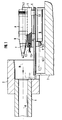
- Fig. 1 shows the rear end of the gun barrel 1 of an artillery gun, not shown, on which the base piece 2 is arranged.
- Behind the gun barrel 1 there is a projectile rifle with a base frame 3 on which a guide track 5 is fastened, on which a carriage 4 is guided in a direction parallel to the barrel core axis R via slide guides 5.1.
- the carriage 4 is coupled via a connecting element 9 to a piston-cylinder drive 6, by means of which it can be accelerated in the direction of arrow B.
- a shock absorber 7 is arranged, which will be explained in more detail below and which has a stop 7.3 on its piston rod 7.2 which is led out of the slide to the front.
- the projectile 8 to be attached lies on the guide rails 4.3 arranged in the longitudinal direction in the carriage 4.
- the carriage 4 with the projectile 8 is shown in the starting position before the acceleration process begins.
- the end position of the slide is indicated in dashed lines by the end position of the piston rod 6.3 of the piston-cylinder drive 6 and the end position of the stop 7.3 of the shock absorber 7.
- stop 7.3 is located directly at the rear end of the gun barrel 1.
- the shock absorber 7 is arranged on the longitudinal center plane M of the carriage 4 and its central axis m runs through the center of mass of the slide 4 in a manner not particularly marked.
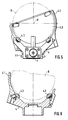
- a shell-like engagement element 4.1 is arranged which, as can be seen from FIGS. 5 and 6, is designed asymmetrically to the longitudinal center plane of the slide, since the projectile 8 is inserted from one side.
- the upper edge of the rear wall 4.2 of the engagement element 4.1 runs such that the point of attack lies above the central axis A of the projectile 8 lying on the guide rails 4.3.
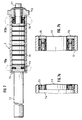
- the shock absorber 7 shows the structure of the shock absorber 7 in more detail.
- the shock absorber 7 has a cylinder 7.1, in which a piston 7.4 is guided, which carries a piston rod 7.2, at the outer end of which, not shown in FIG. 7, the stop 7.3 is arranged.
- the piston rod 7.2 is firmly connected to the piston 7.4 and the guide rod 7.7 and is guided in a holder 7.6 when the piston returns via the guide rod 7.7.
- a friction spring 7.5 is arranged in the space between the guide rod 7.7 and the inner wall of the cylinder 7.1. Friction springs of this type are generally known and their structure can be seen in FIGS. 7a and 7b, which represent an area at the two spring ends.
- the friction spring 7.5 is made up of a number of closed outer and inner rings, the outer rings on their inside and the inner rings on their outside having conical surfaces on which the outer and inner rings touch. If the spring pillar formed from the outer and inner rings is loaded in the direction of the spring axis, the conical surfaces slide into one another and cause the outer rings stretch and the inner rings decrease in diameter. Since outer inner rings are made of spring steel, an elastic compression occurs with correspondingly high forces, the special characteristic of this spring being the strong friction damping due to the friction between the outer and inner rings. In this way, about 2/3 of the energy introduced is converted into thermal energy by friction.
- a shock absorber constructed in this way is particularly advantageous for the projectile attachment described, because in this way the greater part, that is to say about 2/3, of the kinetic energy present in the braking position of the slide 4 is converted by friction, while the remainder for the return of the slide 4 is available in the starting position.
- a shock absorber that converts the entire kinetic energy of the slide when braking and to return the slide to the starting position with the aid of the drive system.
- the piston-cylinder drive 6 of the carriage 4 can in principle be driven hydraulically or pneumatically.
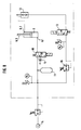
- a pneumatic drive with a control system as shown in FIG. 8 is particularly advantageous.
- the working connection 6.1 of the piston-cylinder drive 6 can be connected via an electromagnetically actuated control valve 10 on the one hand to an outlet and on the other hand to a compressed air reservoir 11.
- the compressed air reservoir 11 is connected to a compressed air source 14 in the usual way.
- the return connection 6.2 of the piston-cylinder drive 6 is via a quick exhaust valve 12 on the one hand to an outlet and on the other hand via a second electromagnetically controllable control valve 13 with the interposition of a pressure limiter on the one hand to the compressed air reservoir 11 and on the other hand to an outlet.
- the control valve 10 is designed as a quick-opening valve, which is characterized by a very short switching time. This ensures that the required volume flow is quickly available on the piston-cylinder drive 6.
Landscapes
- Engineering & Computer Science (AREA)
- General Engineering & Computer Science (AREA)
- Actuator (AREA)
- Braking Arrangements (AREA)
- Preparation Of Clay, And Manufacture Of Mixtures Containing Clay Or Cement (AREA)
- Aiming, Guidance, Guns With A Light Source, Armor, Camouflage, And Targets (AREA)
- Orthopedics, Nursing, And Contraception (AREA)
- Acyclic And Carbocyclic Compounds In Medicinal Compositions (AREA)
- Pharmaceuticals Containing Other Organic And Inorganic Compounds (AREA)
Claims (8)
- Refouloir de projectiles pour l'artillerie comportant, disposé derrière le canon, un traîneau de recul (4) lequel supporte, alignée à la chambre de chargement, une gorge munie à l'extrémité arrière d'un élément de prise (4.1) destiné à la réception du projectile (8) et guidé de manière mobile par un guidage (5.1) sur un rail de guidage (5) s'étendant parallèlement à l'axe du tube du canon et ledit traîneau étant accouplé à un propulseur (6) du type cylindre-piston en vue de l'accélération en direction du tube du canon (1) et présentant un dispositif de frein (7) pour le freinage à une distance prédéterminée avant l'extrémité dudit tube de canon, caractérisé en ce que le dispositif de frein est équipé d'un amortisseur (7) disposé dans le plan médian longitudinal du traîneau (4) et comportant un piston (7.4) mobile à l'intérieur d'un cylindre (7.1) en s'opposant à la force d'un ressort de frottement (7.5), ledit piston supportant une tige de piston (7.2) sortant vers l'avant au-delà de l'extrémité antérieure dudit traîneau (4) et sur laquelle est disposée une butée (7.3), cette disposition étant telle que ladite butée (7.3), dans la position de freinage antérieure du traîneau (4), vient s'appliquer directement à l'extrémité arrière du tube de canon (1).
- Refouloir de projectiles selon la revendication 1, caractérisé en ce que l'axe central de l'amortisseur (7) traverse, au moins approximativement, le centre de gravité du traîneau (4).
- Refouloir de projectiles selon la revendication 1 ou 2, caractérisé en ce que le traîneau (4) présente des rails de guidage (4.3) pour le projectile (8) qui s'étendent en direction longitudinale et que l'élément de prise (4.1) vient saisir l'extrémité arrière du traîneau (4) au-dessus de l'axe médian du projectile (8).
- Refouloir de projectiles selon l'une des revendications 1 à 3, caractérisé en ce que le ressort de frottement (7.5) est réalisé de telle sorte qu'au moins les deux-tiers de l'énergie cinétique du traîneau (4) sont transformés par frottement et que l'énergie résiduelle sert au recul du traîneau (4) vers sa position initiale, l'excédent d'énergie étant absorbé par un autre amortisseur (6).
- Refouloir de projectiles selon la revendication 4, comportant un propulseur pneumatique du type cylindre-piston, caractérisé en ce que ce propulseur du type cylindre-piston (6) sert d'amortisseur complémentaire dont le contenu en gaz est évacué à travers une soupape à étranglement (15) lors du recul du traîneau (4).
- Refouloir de projectiles selon l'une des revendications 1 à 5, comportant un propulseur pneumatique du type cylindre-piston, caractérisé en ce que la sortie active (6.1) du propulseur de type cylindre-piston (6) peut être racordée à travers une première soupape de régulation (10) à ouverture instantanée, soit à un accumulateur d'air comprimé (11) soit à un échappement, tandis que le raccord de recul (6.2) est relié à un échappement à travers un clapet (12) de ventilation instantanée.
- Refouloir de projectile selon la revendication 6, caractérisé en ce que le raccord de recul (6.2) peut être raccordé, à travers une deuxième soupape de régulation (13), soit à un échappement, soit à l'accumulateur d'air comprimé (11).
- Refouloir de projectiles selon la revendicaiton 6, caractérisé en ce que dans l'échappement de la première soupape de régulation (10) est disposé un papillon d'étranglement (15).
Priority Applications (1)
| Application Number | Priority Date | Filing Date | Title |
|---|---|---|---|
| AT89113036T ATE87732T1 (de) | 1988-07-28 | 1989-07-15 | Geschossansetzer fuer artillerie. |
Applications Claiming Priority (2)
| Application Number | Priority Date | Filing Date | Title |
|---|---|---|---|
| DE3825662 | 1988-07-28 | ||
| DE3825662A DE3825662A1 (de) | 1988-07-28 | 1988-07-28 | Geschossansetzer fuer artillerie |
Publications (3)
| Publication Number | Publication Date |
|---|---|
| EP0352584A2 EP0352584A2 (fr) | 1990-01-31 |
| EP0352584A3 EP0352584A3 (en) | 1990-08-16 |
| EP0352584B1 true EP0352584B1 (fr) | 1993-03-31 |
Family
ID=6359765
Family Applications (1)
| Application Number | Title | Priority Date | Filing Date |
|---|---|---|---|
| EP89113036A Expired - Lifetime EP0352584B1 (fr) | 1988-07-28 | 1989-07-15 | Refouloir de projectiles pour artillerie |
Country Status (4)
| Country | Link |
|---|---|
| US (1) | US4957028A (fr) |
| EP (1) | EP0352584B1 (fr) |
| AT (1) | ATE87732T1 (fr) |
| DE (2) | DE3825662A1 (fr) |
Cited By (1)
| Publication number | Priority date | Publication date | Assignee | Title |
|---|---|---|---|---|
| DE102017107442A1 (de) | 2017-04-06 | 2018-10-11 | Krauss-Maffei Wegmann Gmbh & Co. Kg | Vorrichtung zum Laden einer Rohrwaffe mit Munitionskörpern |
Families Citing this family (14)
| Publication number | Priority date | Publication date | Assignee | Title |
|---|---|---|---|---|
| SE9201434L (sv) * | 1992-05-06 | 1993-11-07 | Bofors Ab | Ansättare |
| SE9900152L (sv) * | 1999-01-20 | 2000-06-19 | Bofors Weapon Sys Ab | Sätt och anordning för att hantera artillerigranater vid laddning av artilleripjäser |
| DE19914663A1 (de) * | 1999-03-31 | 2000-10-05 | Krauss Maffei Wegmann Gmbh & C | Geschoßansetzer für ein Artilleriegeschütz |
| RU2148230C1 (ru) * | 1999-06-23 | 2000-04-27 | Государственное унитарное предприятие "Конструкторское бюро приборостроения" | Устройство для досылания выстрела артиллерийского орудия |
| RU2163334C1 (ru) * | 1999-06-25 | 2001-02-20 | Государственное унитарное предприятие Конструкторское бюро приборостроения | Механизм досылания артиллерийской установки |
| FR2796713B1 (fr) * | 1999-07-22 | 2002-09-13 | Giat Ind Sa | Dispositif d'aide au chargement pour artillerie |
| SE9903440L (sv) | 1999-09-23 | 2001-02-26 | Bofors Weapon Sys Ab | Sätt och anordning för laddning av artilleripjäser medelst kastansättning |
| DE19955234A1 (de) * | 1999-11-17 | 2001-05-23 | Krauss Maffei Wegmann Gmbh & C | Geschoßansetzer für Artillerie |
| RU2191336C2 (ru) * | 2000-04-07 | 2002-10-20 | Федеральное государственное унитарное предприятие "Уральское конструкторское бюро транспортного машиностроения" | Способ регулирования скорости досылания управляемой ракеты автоматом заряжания танковой пушки |
| FR2824131B1 (fr) | 2001-04-30 | 2003-12-26 | Giat Ind Sa | Dispositif de refoulement de projectiles |
| US20080216640A1 (en) * | 2005-01-27 | 2008-09-11 | John Brand | Lightweight rammer |
| ITMI20070106A1 (it) * | 2007-01-24 | 2008-07-25 | Beretta Armi Spa | Fucile semiautomatico a corto rinculo |
| FR2945616B1 (fr) * | 2009-05-13 | 2011-07-29 | Nexter Systems | Dispositif de chargement d'une munition |
| CN105571385B (zh) * | 2015-12-15 | 2017-04-05 | 湖北江华机械有限公司 | 设置灵敏供弹装置的榴弹发射器 |
Family Cites Families (12)
| Publication number | Priority date | Publication date | Assignee | Title |
|---|---|---|---|---|
| DE151461C (fr) * | ||||
| US789885A (en) * | 1903-03-24 | 1905-05-16 | Charles Prosper Eugene Schneider | Apparatus for the rapid charging of guns. |
| GB335895A (en) * | 1929-06-01 | 1930-10-01 | Bofors Ab | Automatic loading device for barrel recoil guns |
| US2593412A (en) * | 1943-11-13 | 1952-04-22 | George A Chadwick | Gun rammer |
| GB784739A (en) * | 1950-04-11 | 1957-10-16 | Westinghouse Electric Int Co | Improvements in or relating to automatic rammer mechanisms for guns |
| US3584532A (en) * | 1969-09-16 | 1971-06-15 | Oberlikon Buehrle Holding Ag Z | Automatic gun with ejection actuated rammer |
| SE413342B (sv) * | 1976-03-31 | 1980-05-19 | Bofors Ab | Ansettaranordning |
| US4291611A (en) * | 1979-10-18 | 1981-09-29 | The United States Of America As Represented By The Secretary Of The Army | Automatic loading device |
| SE431794B (sv) * | 1979-12-18 | 1984-02-27 | Bofors Ab | Anordning for styrning av ett ansettarhuvud i dess tversriktning |
| CH662175A5 (en) * | 1984-11-15 | 1987-09-15 | Sig Schweiz Industrieges | Acceleration device for a loading device of a gun |
| DE3607006A1 (de) * | 1986-03-04 | 1987-09-10 | Wegmann & Co | Freiflugansetzer fuer artilleriegeschosse |
| CH664627A5 (de) * | 1986-11-20 | 1988-03-15 | Sig Schweiz Industrieges | Beschleunigungseinrichtung fuer eine ladevorrichtung eines geschuetzes. |
-
1988
- 1988-07-28 DE DE3825662A patent/DE3825662A1/de not_active Withdrawn
-
1989
- 1989-07-14 US US07/380,928 patent/US4957028A/en not_active Expired - Lifetime
- 1989-07-15 DE DE8989113036T patent/DE58903931D1/de not_active Expired - Fee Related
- 1989-07-15 AT AT89113036T patent/ATE87732T1/de not_active IP Right Cessation
- 1989-07-15 EP EP89113036A patent/EP0352584B1/fr not_active Expired - Lifetime
Cited By (4)
| Publication number | Priority date | Publication date | Assignee | Title |
|---|---|---|---|---|
| DE102017107442A1 (de) | 2017-04-06 | 2018-10-11 | Krauss-Maffei Wegmann Gmbh & Co. Kg | Vorrichtung zum Laden einer Rohrwaffe mit Munitionskörpern |
| WO2018184632A1 (fr) | 2017-04-06 | 2018-10-11 | Krauss-Maffei Wegmann Gmbh & Co. Kg | Dispositif pour charger une arme à canon avec des corps de munition |
| DE102017107442B4 (de) * | 2017-04-06 | 2021-03-18 | Krauss-Maffei Wegmann Gmbh & Co. Kg | Vorrichtung zum Laden einer Rohrwaffe mit Munitionskörpern |
| US11015888B2 (en) | 2017-04-06 | 2021-05-25 | Krauss-Maffei Wegmann Gmbh & Co. Kg | Device for loading a barreled weapon with ammunition bodies |
Also Published As
| Publication number | Publication date |
|---|---|
| EP0352584A3 (en) | 1990-08-16 |
| ATE87732T1 (de) | 1993-04-15 |
| DE3825662A1 (de) | 1990-02-08 |
| EP0352584A2 (fr) | 1990-01-31 |
| DE58903931D1 (de) | 1993-05-06 |
| US4957028A (en) | 1990-09-18 |
Similar Documents
| Publication | Publication Date | Title |
|---|---|---|
| EP0352584B1 (fr) | Refouloir de projectiles pour artillerie | |
| DE3505443C2 (fr) | ||
| DE2951904A1 (de) | Abschussvorrichtung fuer ein unterkalibergeschoss | |
| DE1578402A1 (de) | Selbsttaetige Feuerwaffe mit auf einem Traeger ruecklaufbeweglichem Verschlussgehaeuse | |
| CH630723A5 (de) | Vorrichtung zum steuern der kadenz bei feuerstoessen aus einer maschinenkanone. | |
| EP0163626B1 (fr) | Canon | |
| AT507982B1 (de) | Gasdruckbetriebene schusswaffen-vorrichtung | |
| CH668635A5 (de) | Bremshuelse und gegenmasse fuer eine vorrichtung zum rueckstossfreien abschiessen von geschossen. | |
| DE1960023C1 (de) | Automatische Waffe zum Abfeuern von Patronen | |
| DE3015102C2 (de) | Waffenvorlaufdämpfer für eine Maschinenkanone mit Keilverschluß | |
| DE661306C (de) | Schlagbolzenlose Feuerwaffe und Patrone zum Verschiessen aus derselben | |
| DE1578029B1 (de) | Rohrfoermige Abschussvorrichtung fuer Geschosse,insbesondere fuer Lenkgeschosse | |
| DE4009050C2 (fr) | ||
| EP4014003B1 (fr) | Frein de recul et arme à feu à canon | |
| DE2949218C2 (de) | Munitionszündeinrichtung an einer Rohrwaffe | |
| EP0239755B1 (fr) | Refouloir pour canon d'artillerie | |
| EP0114204A2 (fr) | Arme à feu automatique à emprunt de gaz | |
| EP1041355B1 (fr) | Dispositif de refoulement pour canon d'artillerie | |
| DE149402C (fr) | ||
| DE907993C (de) | Leichtgeschuetz | |
| DE10139868A1 (de) | Druckgasbetriebene Schusswaffe mit Rückstoßbremse | |
| DE972758C (de) | Maschinengeschuetz oder Maschinengewehr | |
| DE3206642A1 (de) | Muendungsaufsatz fuer hochleistungsrohrfeuerwaffen | |
| DE1553962B1 (de) | Luftdruckschusswaffe | |
| DE2313984C2 (de) | Führungsring für selbstgetriebene Geschosse |
Legal Events
| Date | Code | Title | Description |
|---|---|---|---|
| PUAI | Public reference made under article 153(3) epc to a published international application that has entered the european phase |
Free format text: ORIGINAL CODE: 0009012 |
|
| AK | Designated contracting states |
Kind code of ref document: A2 Designated state(s): AT BE CH DE FR GB IT LI NL SE |
|
| PUAL | Search report despatched |
Free format text: ORIGINAL CODE: 0009013 |
|
| AK | Designated contracting states |
Kind code of ref document: A3 Designated state(s): AT BE CH DE FR GB IT LI NL SE |
|
| 17P | Request for examination filed |
Effective date: 19900914 |
|
| 17Q | First examination report despatched |
Effective date: 19911121 |
|
| GRAA | (expected) grant |
Free format text: ORIGINAL CODE: 0009210 |
|
| ITF | It: translation for a ep patent filed | ||
| AK | Designated contracting states |
Kind code of ref document: B1 Designated state(s): AT BE CH DE FR GB IT LI NL SE |
|
| PG25 | Lapsed in a contracting state [announced via postgrant information from national office to epo] |
Ref country code: BE Effective date: 19930331 Ref country code: SE Effective date: 19930331 |
|
| REF | Corresponds to: |
Ref document number: 87732 Country of ref document: AT Date of ref document: 19930415 Kind code of ref document: T |
|
| REF | Corresponds to: |
Ref document number: 58903931 Country of ref document: DE Date of ref document: 19930506 |
|
| GBT | Gb: translation of ep patent filed (gb section 77(6)(a)/1977) |
Effective date: 19930413 |
|
| ET | Fr: translation filed | ||
| PG25 | Lapsed in a contracting state [announced via postgrant information from national office to epo] |
Ref country code: AT Effective date: 19930715 |
|
| PLBE | No opposition filed within time limit |
Free format text: ORIGINAL CODE: 0009261 |
|
| STAA | Information on the status of an ep patent application or granted ep patent |
Free format text: STATUS: NO OPPOSITION FILED WITHIN TIME LIMIT |
|
| 26N | No opposition filed | ||
| REG | Reference to a national code |
Ref country code: GB Ref legal event code: IF02 |
|
| PGFP | Annual fee paid to national office [announced via postgrant information from national office to epo] |
Ref country code: DE Payment date: 20070810 Year of fee payment: 19 |
|
| PGFP | Annual fee paid to national office [announced via postgrant information from national office to epo] |
Ref country code: CH Payment date: 20070724 Year of fee payment: 19 |
|
| PGFP | Annual fee paid to national office [announced via postgrant information from national office to epo] |
Ref country code: GB Payment date: 20070730 Year of fee payment: 19 |
|
| PGFP | Annual fee paid to national office [announced via postgrant information from national office to epo] |
Ref country code: IT Payment date: 20070726 Year of fee payment: 19 Ref country code: NL Payment date: 20070717 Year of fee payment: 19 |
|
| PGFP | Annual fee paid to national office [announced via postgrant information from national office to epo] |
Ref country code: FR Payment date: 20070718 Year of fee payment: 19 |
|
| REG | Reference to a national code |
Ref country code: CH Ref legal event code: PFA Owner name: WEGMANN & CO. GMBH Free format text: WEGMANN & CO. GMBH#AUGUST-BODE-STRASSE 1#D-34127 KASSEL (DE) -TRANSFER TO- WEGMANN & CO. GMBH#AUGUST-BODE-STRASSE 1#D-34127 KASSEL (DE) |
|
| REG | Reference to a national code |
Ref country code: CH Ref legal event code: PL |
|
| GBPC | Gb: european patent ceased through non-payment of renewal fee |
Effective date: 20080715 |
|
| NLV4 | Nl: lapsed or anulled due to non-payment of the annual fee |
Effective date: 20090201 |
|
| PG25 | Lapsed in a contracting state [announced via postgrant information from national office to epo] |
Ref country code: DE Free format text: LAPSE BECAUSE OF NON-PAYMENT OF DUE FEES Effective date: 20090203 |
|
| REG | Reference to a national code |
Ref country code: FR Ref legal event code: ST Effective date: 20090331 |
|
| PG25 | Lapsed in a contracting state [announced via postgrant information from national office to epo] |
Ref country code: NL Free format text: LAPSE BECAUSE OF NON-PAYMENT OF DUE FEES Effective date: 20090201 |
|
| PG25 | Lapsed in a contracting state [announced via postgrant information from national office to epo] |
Ref country code: GB Free format text: LAPSE BECAUSE OF NON-PAYMENT OF DUE FEES Effective date: 20080715 Ref country code: LI Free format text: LAPSE BECAUSE OF NON-PAYMENT OF DUE FEES Effective date: 20080731 Ref country code: CH Free format text: LAPSE BECAUSE OF NON-PAYMENT OF DUE FEES Effective date: 20080731 |
|
| PG25 | Lapsed in a contracting state [announced via postgrant information from national office to epo] |
Ref country code: FR Free format text: LAPSE BECAUSE OF NON-PAYMENT OF DUE FEES Effective date: 20080731 Ref country code: IT Free format text: LAPSE BECAUSE OF NON-PAYMENT OF DUE FEES Effective date: 20080715 |