EP0352621A2 - Dispositif de chargement avec trémie de remplissage et glissière de chargement se raccordant à la trémie pour l'alimentation en ordures des installations de combustion - Google Patents
Dispositif de chargement avec trémie de remplissage et glissière de chargement se raccordant à la trémie pour l'alimentation en ordures des installations de combustion Download PDFInfo
- Publication number
- EP0352621A2 EP0352621A2 EP89113260A EP89113260A EP0352621A2 EP 0352621 A2 EP0352621 A2 EP 0352621A2 EP 89113260 A EP89113260 A EP 89113260A EP 89113260 A EP89113260 A EP 89113260A EP 0352621 A2 EP0352621 A2 EP 0352621A2
- Authority
- EP
- European Patent Office
- Prior art keywords
- retaining
- feed device
- compression body
- feed
- compression
- Prior art date
- Legal status (The legal status is an assumption and is not a legal conclusion. Google has not performed a legal analysis and makes no representation as to the accuracy of the status listed.)
- Granted
Links
Images

Classifications
-
- F—MECHANICAL ENGINEERING; LIGHTING; HEATING; WEAPONS; BLASTING
- F23—COMBUSTION APPARATUS; COMBUSTION PROCESSES
- F23G—CREMATION FURNACES; CONSUMING WASTE PRODUCTS BY COMBUSTION
- F23G5/00—Incineration of waste; Incinerator constructions; Details, accessories or control therefor
- F23G5/44—Details; Accessories
- F23G5/442—Waste feed arrangements
- F23G5/444—Waste feed arrangements for solid waste
Definitions
- the invention relates to a feed device with a filling funnel and a subsequent feed chute, at the lower end of which feed pistons are provided for conveying waste to an incineration plant.
- Such a feeding device is known from DE 25 38 380 Al.
- Waste is an extremely heterogeneous fuel, which is produced in different compositions, so that difficulties can arise when feeding the incineration plants.
- the difficulties are based on the fact that, depending on its nature, the garbage glides more easily in one case and thus has a tendency to slip into the incinerator from the hopper, is more bulky with a different composition and does not have good sliding behavior.
- the result of this is, despite the constant operation of the charging pistons, different feed quantities, which, in conjunction with the different calorific values of the waste, lead to a strongly fluctuating heat release and thus to a fluctuating heating output of the combustion system.
- the object of the invention is to design the feeding device of the type mentioned in such a way that the garbage does not slip through the charging pistons and that the garbage is fed evenly into the incineration plant.
- the arrangement of at least one retaining and compression body on at least one loading piston prevents the amount of waste input into the filling funnel from slipping over the loading piston in an uncontrolled manner.
- this retention function it is also achieved during the return stroke of the loading piston that the garbage is compressed somewhat by this retention and compression body, so that the same is compressed in the case of very loose garbage, which increases the density of the fuel and a better metering of the latter Garbage is possible by the next feed of the loading piston.
- the retention and compression bodies can be provided in the area of the front ends of the feed pistons or directly at the front end of the feed pistons.
- Several retention and Compression bodies can be arranged, which can either be arranged side by side or offset from one another.
- the retention and compression body of a loading piston it is also possible for the retention and compression body of a loading piston to be designed as a body which extends over the entire width of the loading piston.
- the retention and compression bodies of adjacent charging pistons can be offset from one another or aligned with one another.
- a first advantageous embodiment for achieving the retention and compression effect is that the retention and compression bodies have a steeply sloping flank towards the rear end of the loading piston and a flatter sloping flank towards the front end of the loading piston. This has the effect that the entrainment effect of these bodies on the garbage lying loosely on the feed piston when feeding the feed piston is less than the retention and compression effect when pushing back the feed piston.
- the retaining and compression bodies move towards the rear end of the feed piston have a flat slope and a steeper slope towards the front end of the feed piston.
- the retention and compression bodies can be designed as flat, upright arranged bodies with a rectangular, trapezoidal, triangular or arched outline in side view.
- the retention and compression bodies can also be designed in the manner of a pyramid, a truncated pyramid, a cone, a truncated cone or a spherical cap.
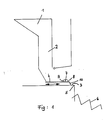
- a feed device comprises a hopper 1, an adjoining feed chute 2, a feed table 3 and feed pistons 4 which can be moved back and forth on the feed table and which discharge the garbage which has been fed into the hopper and slides down in the feed chute 2 via the Be Push the chic edge 5 onto a grate 6 of an incinerator.
- each loading piston in the front area of each loading piston.
- Some of these retaining and compression bodies 7 have a gently sloping flank 8 directed towards the front end of the loading piston 4 and a steeply sloping flank 9 directed towards the rear end of the loading piston 4. This ensures that the piston during the forward stroke promotes the garbage predominantly through its front piston surface 10, i.e. only pushes the garbage lying on the support table 3, while the steep rear flank 9 of the retaining and compression body achieves two effects should.
- the first effect is that the garbage sliding down in the feed chute 2 does not slide uncontrollably over the loading pistons 4 and the second effect is to be seen in that each retention and compression body pushing downward in the feed chute 2 during the reverse stroke Garbage is compressed, only to be taken along on the next piston stroke, which is directed forward.
- Some other retention and compression bodies 7 have one directed towards the front end of the loading piston 4 steeply falling edge 12 and a flat falling edge 11 directed towards the rear end of the loading piston 4. This can be of advantage if the feed chute is at a very steep angle to the feed piston, so that the risk of uncontrolled slipping is out of the question, but the garbage is relatively loose and must be subjected to compression.
- the flank that slopes gently towards the rear creates a compression component that is essentially opposite to the garbage that slides down, as a result of which the garbage is sufficiently pre-compressed.
- the steeply falling flank increases the possibility of conveying the loading piston, which is practiced only by the front piston surface 10 of the loading piston with a flat front flank.
- the retention and compression bodies 7 can have a wide variety of configurations.
- the drawing shows some examples of different design options for the retention and compression bodies, although in practice a single embodiment is preferably chosen for all feed pistons for a feed device.
- the individual loading pistons are provided with the reference number 4 and an additional letter and the retaining bodies are provided with the reference number 7 and also with an additional letter.
- nine charging pistons 4a-4i are arranged, a different variant of a retaining or compression body being provided on each charging piston.
- two retaining and compression bodies 7a designed in the manner of a truncated cone are provided in the vicinity of the front edge of the charging piston 4a, in which, as can be seen from FIG. 3, the forward flank 8 drops more gently than the rearward one Flank 9.
- the retention and compression bodies 7g On the feed piston 4b, two identical retention and compression bodies 7b are again provided, which are designed as narrow, upright bodies.
- the outer contour of these retention and compression bodies 7b is essentially trapezoidal in side view, here too the flank 8 directed towards the front is substantially flatter than the flank 9 directed towards the rear end of the loading piston.
- the retaining and compression bodies 7c on the loading piston 4c are designed in the manner of a pyramid, while the retaining and compression bodies 7d on the loading piston 4d are designed as spherical caps.
- the retention and compression bodies 7e on the loading piston 4e are designed in the manner of a truncated pyramid, the forward flank 8 of these bodies also being essential here, as in the case of the other retention and compression bodies described above is flatter than the flank 9 directed towards the rear end of the loading piston.
- Flat, upright retaining and compression bodies 7f with side walls perpendicular to the piston surface are arranged on the loading piston 4f, the side view being triangular in shape with a front gently sloping flank 8 and one to the rear steeply falling flank 9 are designed.
- the retention and compression bodies 7h on the loading piston 4h are also designed as flat bodies with an arcuate outline.
- a single retaining and compression body 7i which extends across the entire width of the loading piston and has a triangular cross section with a flat front flank 8 and a steeper rear flank 9, is arranged on the loading piston 4i.
- Flat, upright retaining and compression bodies 7h with a triangular outline in side view are arranged on the charging piston 4h, in which, in contrast to the other retaining bodies, the rearward flank 11 slopes gently and the forwardward flank 12 drops steeply.
- Fig. 4 the same retention and compression bodies are provided as in Fig. 3, with one exception, but these retention bodies are offset from one another on one and the same loading piston, so that there are two rows of mutually aligned retention and compression bodies with respect to all loading pistons 3, while in the embodiment according to FIG. 3 all retaining and compression bodies are aligned with one another.
- the loading piston 4i in Fig. 4 carries only a single retaining and compression body 7k, however In contrast to the embodiment according to FIG. 3, this is arranged with its longitudinal axis in the longitudinal direction of the loading piston. In side view it has a rectangular outline.
Landscapes
- Engineering & Computer Science (AREA)
- Environmental & Geological Engineering (AREA)
- Mechanical Engineering (AREA)
- General Engineering & Computer Science (AREA)
- Filling Or Emptying Of Bunkers, Hoppers, And Tanks (AREA)
Applications Claiming Priority (2)
| Application Number | Priority Date | Filing Date | Title |
|---|---|---|---|
| DE3825930 | 1988-07-29 | ||
| DE3825930A DE3825930C1 (fr) | 1988-07-29 | 1988-07-29 |
Publications (3)
| Publication Number | Publication Date |
|---|---|
| EP0352621A2 true EP0352621A2 (fr) | 1990-01-31 |
| EP0352621A3 EP0352621A3 (en) | 1990-08-16 |
| EP0352621B1 EP0352621B1 (fr) | 1992-12-09 |
Family
ID=6359910
Family Applications (1)
| Application Number | Title | Priority Date | Filing Date |
|---|---|---|---|
| EP89113260A Expired - Lifetime EP0352621B1 (fr) | 1988-07-29 | 1989-07-19 | Dispositif de chargement avec trémie de remplissage et glissière de chargement se raccordant à la trémie pour l'alimentation en ordures des installations de combustion |
Country Status (4)
| Country | Link |
|---|---|
| US (1) | US5009171A (fr) |
| EP (1) | EP0352621B1 (fr) |
| JP (1) | JP2682704B2 (fr) |
| DE (1) | DE3825930C1 (fr) |
Cited By (1)
| Publication number | Priority date | Publication date | Assignee | Title |
|---|---|---|---|---|
| EP0443979A3 (en) * | 1990-02-21 | 1992-03-04 | Licencia Holding S.A. | Device for tearing-up and stoking straw |
Families Citing this family (3)
| Publication number | Priority date | Publication date | Assignee | Title |
|---|---|---|---|---|
| DE19834294A1 (de) * | 1998-07-29 | 2000-02-10 | Martin Umwelt & Energietech | Beschickvorrichtung |
| IL145348A0 (en) * | 2001-09-10 | 2003-10-31 | Heavy duty magazine speed loader | |
| US10823404B1 (en) | 2016-03-11 | 2020-11-03 | Pyrodyne Thermal, LLC | Materials handling system for feed injection to thermal kiln retorts |
Family Cites Families (8)
| Publication number | Priority date | Publication date | Assignee | Title |
|---|---|---|---|---|
| US1267439A (en) * | 1916-06-19 | 1918-05-28 | William C Stripe | Stoking mechanism. |
| US1413428A (en) * | 1919-10-28 | 1922-04-18 | Sanford Riley Stoker Co | Coal agitator for mechanical stokers |
| US1400766A (en) * | 1920-03-16 | 1921-12-20 | Thomas A Peebles | Stoking mechanism |
| US2169390A (en) * | 1937-04-15 | 1939-08-15 | Standard Stoker Co Inc | Locomotive tender |
| US2348494A (en) * | 1940-09-23 | 1944-05-09 | Peters Peter Paul | Stoker |
| GB934991A (en) * | 1959-10-15 | 1963-08-21 | James Hodgkinson Salford Ltd | Improvements in fuel feeding devices for furnaces of boilers |
| US3708078A (en) * | 1971-08-26 | 1973-01-02 | Environmental Control Prod Inc | Batch ram feeding apparatus |
| HU203400B (en) * | 1985-02-28 | 1991-07-29 | Sermet Oy | Burner particularly for burning biomass |
-
1988
- 1988-07-29 DE DE3825930A patent/DE3825930C1/de not_active Expired
-
1989
- 1989-07-18 US US07/381,540 patent/US5009171A/en not_active Expired - Lifetime
- 1989-07-19 EP EP89113260A patent/EP0352621B1/fr not_active Expired - Lifetime
- 1989-07-28 JP JP1196483A patent/JP2682704B2/ja not_active Expired - Lifetime
Cited By (1)
| Publication number | Priority date | Publication date | Assignee | Title |
|---|---|---|---|---|
| EP0443979A3 (en) * | 1990-02-21 | 1992-03-04 | Licencia Holding S.A. | Device for tearing-up and stoking straw |
Also Published As
| Publication number | Publication date |
|---|---|
| EP0352621A3 (en) | 1990-08-16 |
| EP0352621B1 (fr) | 1992-12-09 |
| JPH0285603A (ja) | 1990-03-27 |
| DE3825930C1 (fr) | 1989-12-14 |
| US5009171A (en) | 1991-04-23 |
| JP2682704B2 (ja) | 1997-11-26 |
Similar Documents
| Publication | Publication Date | Title |
|---|---|---|
| EP0336081A2 (fr) | Véhicule à ordures | |
| DE3521942A1 (de) | Verfahren zur ausbildung von unvollstaendigen zigarettengruppen in einer zigaretten-verpackungsmaschine | |
| EP0352621B1 (fr) | Dispositif de chargement avec trémie de remplissage et glissière de chargement se raccordant à la trémie pour l'alimentation en ordures des installations de combustion | |
| DE4317393C2 (de) | Ballenpresse | |
| EP0856466A1 (fr) | Dispositif pour transférer une couche de cigarettes | |
| DE69100570T2 (de) | Zurückhalteverfahren und -vorrichtung für einen Ausgabetrichter, insbesondere zum Ausgeben von Zigaretten. | |
| Klein | in Parteiprogrammen¹ | |
| DE2905665C2 (de) | Schneckenförderer | |
| DE2936198A1 (de) | Vorrichtung zur aufhaldung von schuettguetern unterschiedlicher korngroesse | |
| EP0186731B1 (fr) | Auxiliaire pour l'évacuation des résidus de combustion des installations de combustion, en particulier des incinérateurs | |
| WO1986001580A1 (fr) | Tremie de chargement pour usines d'incineration d'ordures | |
| DE2400547B2 (de) | Bunker mit austragvorrichtung | |
| DE69210282T2 (de) | Tragelement für Behälter | |
| DE3410901A1 (de) | Verteilvorrichtung | |
| DE3153697C2 (fr) | ||
| EP1190774A2 (fr) | Dispositif de coupe | |
| EP0489367B1 (fr) | Dispositif pour doser des granulés | |
| DE7636986U1 (de) | Vorrichtung, insbesondere drillmaschine, zum dosieren teilchenfoermigen materials | |
| DE3103836C2 (fr) | ||
| DE3521781C1 (de) | Beschickungsvorrichtung | |
| DE7737255U1 (de) | Lade- und pressvorrichtung fuer muellwagen | |
| DE3412427A1 (de) | Montageeinrichtung fuer axialsicherungen | |
| CH670438A5 (en) | Device for producing stack of loose material - has sliding ram and distributor elements flattening out top | |
| DE409326C (de) | Verteiler fuer die Hoelzer bei Zuendholzmaschinen | |
| DE2928795C2 (de) | Selbstverkäufer |
Legal Events
| Date | Code | Title | Description |
|---|---|---|---|
| PUAI | Public reference made under article 153(3) epc to a published international application that has entered the european phase |
Free format text: ORIGINAL CODE: 0009012 |
|
| AK | Designated contracting states |
Kind code of ref document: A2 Designated state(s): BE CH FR GB IT LI NL |
|
| ITCL | It: translation for ep claims filed |
Representative=s name: STUDIO JAUMANN |
|
| GBC | Gb: translation of claims filed (gb section 78(7)/1977) | ||
| TCNL | Nl: translation of patent claims filed | ||
| EL | Fr: translation of claims filed | ||
| PUAL | Search report despatched |
Free format text: ORIGINAL CODE: 0009013 |
|
| AK | Designated contracting states |
Kind code of ref document: A3 Designated state(s): BE CH FR GB IT LI NL |
|
| RHK1 | Main classification (correction) |
Ipc: F23G 5/44 |
|
| 17P | Request for examination filed |
Effective date: 19900831 |
|
| 17Q | First examination report despatched |
Effective date: 19911112 |
|
| GRAA | (expected) grant |
Free format text: ORIGINAL CODE: 0009210 |
|
| AK | Designated contracting states |
Kind code of ref document: B1 Designated state(s): BE CH FR GB IT LI NL |
|
| ET | Fr: translation filed | ||
| ITF | It: translation for a ep patent filed | ||
| GBT | Gb: translation of ep patent filed (gb section 77(6)(a)/1977) |
Effective date: 19930222 |
|
| PLBE | No opposition filed within time limit |
Free format text: ORIGINAL CODE: 0009261 |
|
| STAA | Information on the status of an ep patent application or granted ep patent |
Free format text: STATUS: NO OPPOSITION FILED WITHIN TIME LIMIT |
|
| 26N | No opposition filed | ||
| REG | Reference to a national code |
Ref country code: GB Ref legal event code: IF02 |
|
| PGFP | Annual fee paid to national office [announced via postgrant information from national office to epo] |
Ref country code: CH Payment date: 20080715 Year of fee payment: 20 |
|
| PGFP | Annual fee paid to national office [announced via postgrant information from national office to epo] |
Ref country code: FR Payment date: 20080715 Year of fee payment: 20 Ref country code: IT Payment date: 20080726 Year of fee payment: 20 Ref country code: NL Payment date: 20080716 Year of fee payment: 20 |
|
| PGFP | Annual fee paid to national office [announced via postgrant information from national office to epo] |
Ref country code: GB Payment date: 20080722 Year of fee payment: 20 |
|
| PGFP | Annual fee paid to national office [announced via postgrant information from national office to epo] |
Ref country code: BE Payment date: 20080814 Year of fee payment: 20 |
|
| REG | Reference to a national code |
Ref country code: CH Ref legal event code: PL |
|
| REG | Reference to a national code |
Ref country code: GB Ref legal event code: PE20 Expiry date: 20090718 |
|
| NLV7 | Nl: ceased due to reaching the maximum lifetime of a patent |
Effective date: 20090719 |
|
| PG25 | Lapsed in a contracting state [announced via postgrant information from national office to epo] |
Ref country code: NL Free format text: LAPSE BECAUSE OF EXPIRATION OF PROTECTION Effective date: 20090719 Ref country code: GB Free format text: LAPSE BECAUSE OF EXPIRATION OF PROTECTION Effective date: 20090718 |