EP0352622A2 - Appareil de chauffage à haute fréquence comprenant un support amovible formant étanchéité - Google Patents
Appareil de chauffage à haute fréquence comprenant un support amovible formant étanchéité Download PDFInfo
- Publication number
- EP0352622A2 EP0352622A2 EP89113262A EP89113262A EP0352622A2 EP 0352622 A2 EP0352622 A2 EP 0352622A2 EP 89113262 A EP89113262 A EP 89113262A EP 89113262 A EP89113262 A EP 89113262A EP 0352622 A2 EP0352622 A2 EP 0352622A2
- Authority
- EP
- European Patent Office
- Prior art keywords
- heating chamber
- shelf
- mounting rack
- opening
- wall surfaces
- Prior art date
- Legal status (The legal status is an assumption and is not a legal conclusion. Google has not performed a legal analysis and makes no representation as to the accuracy of the status listed.)
- Granted
Links
- 238000010438 heat treatment Methods 0.000 title claims abstract description 94
- 238000007789 sealing Methods 0.000 claims abstract description 19
- 239000000463 material Substances 0.000 claims description 11
- 229920001296 polysiloxane Polymers 0.000 claims description 7
- 238000001125 extrusion Methods 0.000 claims description 2
- 238000000638 solvent extraction Methods 0.000 claims description 2
- 238000005192 partition Methods 0.000 abstract description 2
- 238000012856 packing Methods 0.000 description 49
- 210000002105 tongue Anatomy 0.000 description 10
- 238000012423 maintenance Methods 0.000 description 8
- 230000002093 peripheral effect Effects 0.000 description 7
- 235000013305 food Nutrition 0.000 description 6
- 230000005284 excitation Effects 0.000 description 5
- 235000021056 liquid food Nutrition 0.000 description 4
- 230000000593 degrading effect Effects 0.000 description 2
- 239000004743 Polypropylene Substances 0.000 description 1
- XUIMIQQOPSSXEZ-UHFFFAOYSA-N Silicon Chemical compound [Si] XUIMIQQOPSSXEZ-UHFFFAOYSA-N 0.000 description 1
- 238000007792 addition Methods 0.000 description 1
- 238000011109 contamination Methods 0.000 description 1
- 230000003247 decreasing effect Effects 0.000 description 1
- 239000013013 elastic material Substances 0.000 description 1
- 239000003365 glass fiber Substances 0.000 description 1
- 238000003780 insertion Methods 0.000 description 1
- 230000037431 insertion Effects 0.000 description 1
- 238000000034 method Methods 0.000 description 1
- 238000012986 modification Methods 0.000 description 1
- 230000004048 modification Effects 0.000 description 1
- 238000007747 plating Methods 0.000 description 1
- -1 polypropylene Polymers 0.000 description 1
- 229920001155 polypropylene Polymers 0.000 description 1
- 229920000136 polysorbate Polymers 0.000 description 1
- 238000009877 rendering Methods 0.000 description 1
- 230000000717 retained effect Effects 0.000 description 1
- 229920002379 silicone rubber Polymers 0.000 description 1
- 239000004945 silicone rubber Substances 0.000 description 1
- 229920003002 synthetic resin Polymers 0.000 description 1
- 239000000057 synthetic resin Substances 0.000 description 1
- 230000000007 visual effect Effects 0.000 description 1
Images
Classifications
-
- F—MECHANICAL ENGINEERING; LIGHTING; HEATING; WEAPONS; BLASTING
- F24—HEATING; RANGES; VENTILATING
- F24C—DOMESTIC STOVES OR RANGES ; DETAILS OF DOMESTIC STOVES OR RANGES, OF GENERAL APPLICATION
- F24C7/00—Stoves or ranges heated by electric energy
- F24C7/02—Stoves or ranges heated by electric energy using microwaves
-
- H—ELECTRICITY
- H05—ELECTRIC TECHNIQUES NOT OTHERWISE PROVIDED FOR
- H05B—ELECTRIC HEATING; ELECTRIC LIGHT SOURCES NOT OTHERWISE PROVIDED FOR; CIRCUIT ARRANGEMENTS FOR ELECTRIC LIGHT SOURCES, IN GENERAL
- H05B6/00—Heating by electric, magnetic or electromagnetic fields
- H05B6/64—Heating using microwaves
- H05B6/74—Mode transformers or mode stirrers
- H05B6/745—Rotatable stirrers
-
- H—ELECTRICITY
- H05—ELECTRIC TECHNIQUES NOT OTHERWISE PROVIDED FOR
- H05B—ELECTRIC HEATING; ELECTRIC LIGHT SOURCES NOT OTHERWISE PROVIDED FOR; CIRCUIT ARRANGEMENTS FOR ELECTRIC LIGHT SOURCES, IN GENERAL
- H05B6/00—Heating by electric, magnetic or electromagnetic fields
- H05B6/64—Heating using microwaves
- H05B6/6408—Supports or covers specially adapted for use in microwave heating apparatus
-
- H—ELECTRICITY
- H05—ELECTRIC TECHNIQUES NOT OTHERWISE PROVIDED FOR
- H05B—ELECTRIC HEATING; ELECTRIC LIGHT SOURCES NOT OTHERWISE PROVIDED FOR; CIRCUIT ARRANGEMENTS FOR ELECTRIC LIGHT SOURCES, IN GENERAL
- H05B6/00—Heating by electric, magnetic or electromagnetic fields
- H05B6/64—Heating using microwaves
- H05B6/6426—Aspects relating to the exterior of the microwave heating apparatus, e.g. metal casing, power cord
Definitions
- This invention relates to a high frequency heating apparatus, such as a microwave oven, and, more particularly, to an attachment structure of a mounting rack thereof.
- a microwave oven range includes a mounting rack (hereinafter referred to as a shelf) situated at a lower portion of a housing, and on which is placed food or the like for heating, and a radiating unit, mounted on an upper portion of the housing, and which radiates microwaves downward, unto food placed on the shelf.
- a mounting rack hereinafter referred to as a shelf
- a radiating unit mounted on an upper portion of the housing, and which radiates microwaves downward, unto food placed on the shelf.
- the conventional microwave oven range includes an excitation port of a waveguide serving as a microwave radiating unit and a stirrer fan in a bottom portion of a heating chamber.
- the heating chamber is partitioned into upper and lower spaces by a food mounting shelf.
- the stirrer fan is arranged in the lower space partitioned by the shelf.
- the shelf for supporting food is generally a flat one-piece member. Therefore, when liquid food is spilled, the spilled food may undesirably fall in a lower stirrer fan chamber through a gap between the shelf and a wall surface of the heating chamber.
- a shelf 1 is mounted in a heating chamber 2, and a gap between the peripheral edge of the shelf 1 and a wall surface 3 of the heating chamber 2 is filled with a silicone material 4 to perform sealing.
- a syringe is inserted in the small heating chamber 2, and the silicone material must be injected with a visual observation along the gap. This operation is time-consuming and it is difficult to inject a uniform amount of silicone material, thus degrading operation efficiency.
- a packing 7 is mounted at a peripheral edge of a shelf 1, and the shelf 1 is fitted in a heating chamber 2 from above, so that the gap between the peripheral edge of the shelf 1 and a wall surface 3 of the heating chamber 2 is sealed by the packing 7.
- an upper portion of the packing 7 mounted at the peripheral edge of the shelf 1 is pressed by a finger and elastically deformed, making it easy to detach from the shelf 1, which in turn can then be easily detached.
- the silicone material 4 cannot be easily detached during maintenance service. Therefore, it is difficult to easily detach the shelf 1.
- the system that the packing 7 is mounted at the peripheral portion of the shelf 1 to achieve easy detachment of the packing 7 is proposed. However, as described above, when this system is employed, the packing 7 is apt to be detached upon assembly.
- a high frequency heating apparatus comprising: a housing including a heating chamber having an opening at one end, a door for exposing/closing the opening of the heating chamber, and means for supplying a heating high frequency output from a bottom portion of the heating chamber to the inside of the heating chamber; a mounting rack for partitioning the bottom portion of the heating chamber from an upper portion thereof, and for supporting an object to be heated, the mounting rack having engaging portions engaged with a lower edge of the opening of the heating chamber, by means of which the mounting rack can pivot about the engaging portions and be detached from the lower edge, and having recesses respectively formed on lower surfaces of edges opposite to wall surfaces of the heating chamber except for the opening; and sealing means for sealing gaps between the wall surfaces of the heating chamber, except for the opening, and the opposite edges of the mounting rack, the sealing means having a projection fitted in a corresponding one of the recesses of the mounting rack, a base portion formed integral with the projection and brought into tight contact with each of the opposite edges of the mounting rack, and a tongue
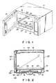
- Figs. 1 to 7 show a first embodiment of the present invention.
- reference numeral 11 denotes a housing of a microwave oven, and numeral 12, a high frequency heating chamber formed within the housing 11.
- the heating chamber 12 includes a ceiling portion 121 and a bottom portion 122.
- An opening 20 is formed on one side of the heating chamber 12, with wall surfaces 123, 124, and 125 being formed on the remaining three sides.
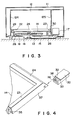
- the (sealed-in) shelf 14 is arranged in the heating chamber 12 such that it partitions a bottom space 13 from an upper space.
- the shelf 14 is composed of polypropylene synthetic resin or glass fiber material which is highly heat-resistant and is substantially free from high frequency loss.
- an excitation port 16 of a waveguide 15 is formed in the center of a lower surface in the bottom space 13.
- High frequency waves oscillated by a magnetron 17 are guided through the waveguide 15, and are radiated in the heating chamber 12 via the excitation port 16.
- a stirrer fan 18 is arranged above the excitation port 16, and causes the high frequency waves to be radiated uniformly throughout the heating chamber 12.
- the opening 20 is integrally formed with a front edge 19 of the housing 11 in which the heating chamber 12 is formed. The opening 20 is closed by a door 21 pivotally supported by one end of the front edge 19.
- the shelf 14 has is plate-like in shape, in order for it to retain liquid food in the event that it is spilled.
- upright portions 22, 23, and 24 are formed on the left and right sides, and on the rear end of the shelf 14, respectively, for this purpose.
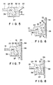
- a surface 25, which is inclined downward in the forward direction, is formed at the front end of the shelf 14, and as is shown in Figs. 2 and 3, the shelf 14 is supported above the bottom surface of the heating chamber 12 by a plurality of legs 26. Located thus, the lower surface of the front end of the shelf 14 is brought into contact with a flange 27 formed at the front edge 19 of the heating chamber 12.
- the engaging portions 28 When the engaging portions 28 are engaged with the flange 27 of the front edge 19 by sandwiching the flange 27 with their pawls 281, the shelf 14 can be pivoted about the engaging portions 28.
- the pawls 281 may be omitted, and the engaging portions 28 may be directly engaged with the flange 27.
- Packings 29, 30, and 31 are detachably mounted to the upright portions 22, 23, and 24 which are formed at the left and right sides, and the rear end of the shelf 14, respectively.
- the packings 29, 30, and 31 consist of an elastic material having heat resistance and a sealing property, such as a silicone rubber material.
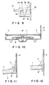
- the packings 29, 30, and 31 are elongated members formed by extrusion molding, each having a sectional shape, as represented by the packing 31 in Fig. 5.
- Each packing 29, 30, or 31 includes a mounting base 32, and a tongue 33 having an interference ⁇ .
- the tongue 33 is urged against a wall surface 34 of the heating chamber 12, and is elastically deformed to be brought into tight contact with the wall surface 34. Even if an error occurs in a sealing size ⁇ (Fig.
- each packing 29, 30, or 31 includes a projection 36 fitted in a recess 35 (to be described later) formed on the shelf 14 side, and a contact surface 38 inclined along an inclined surface 37 (to be described later) similarly formed on the shelf 14 side, and brought into tight contact with the inclined surface 37.
- the recess 35 is formed on each lower surface of the corresponding upright portion 22, 23, or 24 along the longitudinal direction.
- the inclined surface 37 is formed on each end face of the corresponding upright portion 22, 23, or 24 along the longitudinal direction.
- the inclined surface 37 is inclined such that a lower contact portion is located nearer the wall surface 34 of the heating chamber 12 than an upper portion with respect to the direction perpendicular to the plate surface of the shelf 14.
- the mounting base 32 of each packing 29, 30, or 31 is slid and inserted from one end of the corresponding upright portion 22, 23, or 24, and the projection 36 and the contact surface 38 are fitted in the recess 35 and the inclined surface 37, respectively, as shown in Fig. 5.
- the engaging portions 28 mounted at the front end of the shelf 14 are engaged with the flange 27 of the front edge 19 of the heating chamber 12, and the front end of the shelf 14 is locked.
- the rear end is pivoted downward about the front end toward the inside of the heating chamber 12, and the shelf 14 is inserted into the heating chamber 12.
- the tongues 33 of the packings 29, 30, and 31 are brought into tight contact with the wall surfaces 34 of the heating chamber 12, and are brought into slidable contact in the direction indicated by an arrow B while being warped in the direction indicated an arrow A, as shown in Fig. 6.
- the packings 29, 30, and 31 are sandwiched between the shelf 14 and the wall surfaces 34 of the heating chamber 12, and urged against the wall surfaces 34.
- forces are dispersed in the direction indicated by an arrow X′ along the inclined surface 37.
- the surface 37 and the contact surface 38 are both inclined so that the contact area of these surfaces, i.e., friction and engaging resistance is increased, and a large force tends not to act on the projections 36 of the packings 29, 30, and 31 respectively fitted in the recesses 35 on the shelf 14 side.
- the packings 29, 30, and 31 cannot easily be detached from the shelf 14. More specifically, when the shelf 14 is mounted in place, this prevents the packings 29, 30, and 31 from becoming detached. As shown in Figs.
- the shelf 14 when the shelf 14 is located so that the legs 26 abut against the bottom surface of the heating chamber 12, the shelf 14 is horizontally inclined.
- the tongues 33 of the packings 29, 30, and 31 are warped in the A direction (upward), and elastically brought into tight contact with the wall surfaces 34 of the heating chamber 12, so that the gaps between the tongues 33 and the wall surfaces 34 are watertightly sealed.
- the shelf 14 When the shelf 14 is detached from the heating chamber 12, the upper portions of the packings 29, 30, and 31 are urged in the direction indicated by an arrow C (downward) in Fig. 7, and the packings are elastically deformed to decrease the thickness of their sectional areas, so that the shelf 14 is flexed downward. Then, the shelf 14 is moved upward about its front end, so that the packings 29, 30, and 31 can be easily detached downward from the shelf 14. Therefore, the shelf 14 can be easily detached during maintenance service.
- Fig. 8 shows a second embodiment of the present invention.
- the thickness of a mounting base 32 of each packing 29, 30, or 31 is decreased, and a tongue 33 is brought into contact with a wall surface 34 of a heating chamber 12.
- the friction resistance between the packings 29, 30, and 31 and the wall surfaces 34 of the heating chamber 12 is reduced, so that the packings 29, 30, and 31 cannot be further easily detached upon attachment of the shelf 14.
- the packings 29, 30, and 31 can be further easily detached during maintenance service.
- Fig. 9 shows a third embodiment of the present invention.
- an inclined surface 37 on a shelf 14 and a contact surface 38 on a packing 31 are inclined in a direction opposite to that in the first embodiment. More specifically, the surfaces 37 and 38 are inclined such that an upper contact portion is located nearer the wall surface 34 of the heating chamber 12 than a lower portion with respect to the direction perpendicular to the surface of the shelf 14. Even if this arrangement is employed, the prescribed object of the present invention can be achieved.
- a high frequency heating apparatus for supplying a high frequency wave from a bottom portion in a heating chamber to the inside of the heating chamber, the bottom portion of the heating chamber is partitioned by a shelf.
- the front end of the shelf is pivotally engaged with a front opening edge of the heating chamber, and the shelf is pivoted about the front end serving as a fulcrum and is mounted in the heating chamber.
- Packings are provided at the left and right sides, and the rear end. The packings are brought into tight contact with the wall surfaces of the heating chamber to seal the gap between the shelf and the wall surfaces of the heating chamber.
- the shelf includes recesses formed on the lower surfaces of the left, right, and rear edges, and inclined surfaces formed on the end faces of the left, right, and rear edges to be inclined in the direction perpendicular to a plating surface of the shelf.
- Each packing includes a projection fitted in the corresponding recess in the shelf, and a contact surface inclined along the inclined portion of the shelf and brought into tight contact with the inclined surface on the shelf.
- a high frequency heating apparatus in which the packings can be prevented from detaching from the shelf upon assembly but can be easily detached from the shelf during routine maintenance, thereby rendering removal of the shelf from the heating chamber a simple and straightford process.
- a high frequency heating apparatus which can achieve an easy assembly operation as compared with the case wherein the gap between the peripheral edge of the shield and the wall surfaces of the heating chamber is filled with the silicone material after the shelf is mounted in the heating chamber, and can realize a good outer appearance because the shelf is arranged in the heating chamber with high reliability.
Landscapes
- Physics & Mathematics (AREA)
- Electromagnetism (AREA)
- Engineering & Computer Science (AREA)
- Power Engineering (AREA)
- Chemical & Material Sciences (AREA)
- Combustion & Propulsion (AREA)
- Mechanical Engineering (AREA)
- General Engineering & Computer Science (AREA)
- Electric Ovens (AREA)
- Constitution Of High-Frequency Heating (AREA)
Applications Claiming Priority (2)
| Application Number | Priority Date | Filing Date | Title |
|---|---|---|---|
| JP63184705A JPH0237216A (ja) | 1988-07-26 | 1988-07-26 | 高周波加熱装置 |
| JP184705/88 | 1988-07-26 |
Publications (3)
| Publication Number | Publication Date |
|---|---|
| EP0352622A2 true EP0352622A2 (fr) | 1990-01-31 |
| EP0352622A3 EP0352622A3 (fr) | 1991-10-02 |
| EP0352622B1 EP0352622B1 (fr) | 1994-09-07 |
Family
ID=16157930
Family Applications (1)
| Application Number | Title | Priority Date | Filing Date |
|---|---|---|---|
| EP89113262A Expired - Lifetime EP0352622B1 (fr) | 1988-07-26 | 1989-07-19 | Appareil de chauffage à haute fréquence comprenant un support amovible formant étanchéité |
Country Status (6)
| Country | Link |
|---|---|
| US (1) | US4954680A (fr) |
| EP (1) | EP0352622B1 (fr) |
| JP (1) | JPH0237216A (fr) |
| KR (1) | KR910004387B1 (fr) |
| CA (1) | CA1322578C (fr) |
| DE (1) | DE68918019T2 (fr) |
Cited By (2)
| Publication number | Priority date | Publication date | Assignee | Title |
|---|---|---|---|---|
| EP1434008A3 (fr) * | 2002-12-27 | 2011-03-23 | LG Electronics, Inc. | Assemblage d'un chambre de cuisinière dans un four à microondes |
| USD913029S1 (en) * | 2019-01-03 | 2021-03-16 | Andre Davis | Portable microwave |
Families Citing this family (8)
| Publication number | Priority date | Publication date | Assignee | Title |
|---|---|---|---|---|
| US5155318A (en) * | 1991-12-17 | 1992-10-13 | Raytheon Company | Microwave oven griddle seal |
| US5938968A (en) * | 1997-08-28 | 1999-08-17 | Ogg; Starla | Retractable shelf assembly for a microwave oven |
| KR100465191B1 (ko) * | 2002-02-06 | 2005-01-13 | 삼성전자주식회사 | 전자렌지 |
| KR20040021719A (ko) * | 2002-08-29 | 2004-03-11 | 삼성전자주식회사 | 전자렌지용 랙 및 전자렌지 세트 |
| US20110084065A1 (en) * | 2009-10-09 | 2011-04-14 | Charles Gibson | Slidable Tray Assembly for Microwave Oven |
| CN106465490B (zh) * | 2014-07-10 | 2019-11-01 | 松下知识产权经营株式会社 | 微波加热装置 |
| CN110320097B (zh) * | 2019-07-08 | 2022-04-15 | 菏泽学院 | 一种用于高温岩石力学实验的加热装置及其加热方法 |
| US20240292501A1 (en) * | 2023-02-24 | 2024-08-29 | B/E Aerospace, Inc. | Integrated cavity plate seal |
Family Cites Families (5)
| Publication number | Priority date | Publication date | Assignee | Title |
|---|---|---|---|---|
| DE2946767A1 (de) * | 1979-11-20 | 1981-06-11 | Licentia Patent-Verwaltungs-Gmbh, 6000 Frankfurt | Kombinierter herd fuer mikrowellen- und konventionellen widerstands-heizbetrieb |
| US4316069A (en) * | 1979-12-03 | 1982-02-16 | General Electric Company | Microwave oven excitation system |
| JPS60130094A (ja) * | 1983-12-15 | 1985-07-11 | 松下電器産業株式会社 | 高周波加熱装置 |
| EP0173491B1 (fr) * | 1984-08-14 | 1989-11-08 | Microwave Ovens Limited | Four à micro-ondes |
| JPS62218736A (ja) * | 1986-03-19 | 1987-09-26 | Matsushita Electric Ind Co Ltd | 高周波加熱装置 |
-
1988
- 1988-07-26 JP JP63184705A patent/JPH0237216A/ja active Pending
-
1989
- 1989-07-17 US US07/380,453 patent/US4954680A/en not_active Expired - Fee Related
- 1989-07-19 EP EP89113262A patent/EP0352622B1/fr not_active Expired - Lifetime
- 1989-07-19 DE DE68918019T patent/DE68918019T2/de not_active Expired - Fee Related
- 1989-07-25 KR KR1019890010497A patent/KR910004387B1/ko not_active Expired
- 1989-07-25 CA CA000606540A patent/CA1322578C/fr not_active Expired - Fee Related
Cited By (2)
| Publication number | Priority date | Publication date | Assignee | Title |
|---|---|---|---|---|
| EP1434008A3 (fr) * | 2002-12-27 | 2011-03-23 | LG Electronics, Inc. | Assemblage d'un chambre de cuisinière dans un four à microondes |
| USD913029S1 (en) * | 2019-01-03 | 2021-03-16 | Andre Davis | Portable microwave |
Also Published As
| Publication number | Publication date |
|---|---|
| EP0352622A3 (fr) | 1991-10-02 |
| KR910004387B1 (ko) | 1991-06-26 |
| DE68918019T2 (de) | 1995-02-23 |
| JPH0237216A (ja) | 1990-02-07 |
| CA1322578C (fr) | 1993-09-28 |
| KR900002035A (ko) | 1990-02-28 |
| DE68918019D1 (de) | 1994-10-13 |
| US4954680A (en) | 1990-09-04 |
| EP0352622B1 (fr) | 1994-09-07 |
Similar Documents
| Publication | Publication Date | Title |
|---|---|---|
| EP0352622B1 (fr) | Appareil de chauffage à haute fréquence comprenant un support amovible formant étanchéité | |
| KR960034871A (ko) | 전자레인지 | |
| US6834974B2 (en) | Lamp assembly, backlight assembly and liquid crystal display apparatus having the same | |
| CN1317531C (zh) | 灯组件和具有灯组件的烹饪装置 | |
| US7025489B2 (en) | Assembling frame for back light modules | |
| CN212255936U (zh) | 显示装置 | |
| GB2076530A (en) | A High Frequency Heating Appliance | |
| US20050006118A1 (en) | Adaptable emi/rfi shielding for a front-panel attachment to an enclosure | |
| KR102938390B1 (ko) | 조리기기 | |
| KR100644804B1 (ko) | 액정표시장치 및 이의 조립방법 | |
| JPH01219420A (ja) | 高周波加熱装置 | |
| CN221444316U (zh) | 微波炉用烹调器具以及微波炉 | |
| US20240011643A1 (en) | Cooking tray and cooking appliance having the same | |
| US20240292501A1 (en) | Integrated cavity plate seal | |
| US20220322501A1 (en) | Cooking apparatus | |
| JP2004349042A (ja) | 高周波加熱装置 | |
| JPH0210024A (ja) | 高周波加熱装置 | |
| KR100983588B1 (ko) | 액정표시장치 | |
| JP2010117108A (ja) | 蒸気発生機能付き高周波加熱装置 | |
| WO1992008762A1 (fr) | Procede et dispositif de fixation d'elements au moyen d'un polymere | |
| KR100246893B1 (ko) | 전자렌지용 도어 | |
| KR100843672B1 (ko) | 탄성체를 사용하여 도광판을 고정하는 구조를 갖는액정표시장치 | |
| KR900002832Y1 (ko) | 고주파 차단용 전자렌지 도아장치 | |
| JPS6155754B2 (fr) | ||
| JPH09318067A (ja) | 電子レンジ |
Legal Events
| Date | Code | Title | Description |
|---|---|---|---|
| PUAI | Public reference made under article 153(3) epc to a published international application that has entered the european phase |
Free format text: ORIGINAL CODE: 0009012 |
|
| 17P | Request for examination filed |
Effective date: 19890816 |
|
| AK | Designated contracting states |
Kind code of ref document: A2 Designated state(s): DE FR GB |
|
| PUAL | Search report despatched |
Free format text: ORIGINAL CODE: 0009013 |
|
| AK | Designated contracting states |
Kind code of ref document: A3 Designated state(s): DE FR GB |
|
| 17Q | First examination report despatched |
Effective date: 19921124 |
|
| GRAA | (expected) grant |
Free format text: ORIGINAL CODE: 0009210 |
|
| AK | Designated contracting states |
Kind code of ref document: B1 Designated state(s): DE FR GB |
|
| REF | Corresponds to: |
Ref document number: 68918019 Country of ref document: DE Date of ref document: 19941013 |
|
| ET | Fr: translation filed | ||
| PLBE | No opposition filed within time limit |
Free format text: ORIGINAL CODE: 0009261 |
|
| STAA | Information on the status of an ep patent application or granted ep patent |
Free format text: STATUS: NO OPPOSITION FILED WITHIN TIME LIMIT |
|
| PGFP | Annual fee paid to national office [announced via postgrant information from national office to epo] |
Ref country code: GB Payment date: 19950710 Year of fee payment: 7 |
|
| PGFP | Annual fee paid to national office [announced via postgrant information from national office to epo] |
Ref country code: FR Payment date: 19950711 Year of fee payment: 7 |
|
| PGFP | Annual fee paid to national office [announced via postgrant information from national office to epo] |
Ref country code: DE Payment date: 19950725 Year of fee payment: 7 |
|
| 26N | No opposition filed | ||
| PG25 | Lapsed in a contracting state [announced via postgrant information from national office to epo] |
Ref country code: GB Effective date: 19960719 |
|
| GBPC | Gb: european patent ceased through non-payment of renewal fee |
Effective date: 19960719 |
|
| PG25 | Lapsed in a contracting state [announced via postgrant information from national office to epo] |
Ref country code: FR Effective date: 19970328 |
|
| PG25 | Lapsed in a contracting state [announced via postgrant information from national office to epo] |
Ref country code: DE Effective date: 19970402 |
|
| REG | Reference to a national code |
Ref country code: FR Ref legal event code: ST |