EP0352627B1 - Reproducteur de son - Google Patents
Reproducteur de son Download PDFInfo
- Publication number
- EP0352627B1 EP0352627B1 EP89113282A EP89113282A EP0352627B1 EP 0352627 B1 EP0352627 B1 EP 0352627B1 EP 89113282 A EP89113282 A EP 89113282A EP 89113282 A EP89113282 A EP 89113282A EP 0352627 B1 EP0352627 B1 EP 0352627B1
- Authority
- EP
- European Patent Office
- Prior art keywords
- test tone
- decoder
- sound
- signal
- test
- Prior art date
- Legal status (The legal status is an assumption and is not a legal conclusion. Google has not performed a legal analysis and makes no representation as to the accuracy of the status listed.)
- Expired - Lifetime
Links
Images


Classifications
-
- H—ELECTRICITY
- H04—ELECTRIC COMMUNICATION TECHNIQUE
- H04S—STEREOPHONIC SYSTEMS
- H04S7/00—Indicating arrangements; Control arrangements, e.g. balance control
- H04S7/40—Visual indication of stereophonic sound image
-
- H—ELECTRICITY
- H04—ELECTRIC COMMUNICATION TECHNIQUE
- H04S—STEREOPHONIC SYSTEMS
- H04S7/00—Indicating arrangements; Control arrangements, e.g. balance control
- H04S7/30—Control circuits for electronic adaptation of the sound field
- H04S7/301—Automatic calibration of stereophonic sound system, e.g. with test microphone
-
- H—ELECTRICITY
- H04—ELECTRIC COMMUNICATION TECHNIQUE
- H04S—STEREOPHONIC SYSTEMS
- H04S3/00—Systems employing more than two channels, e.g. quadraphonic
-
- H—ELECTRICITY
- H04—ELECTRIC COMMUNICATION TECHNIQUE
- H04S—STEREOPHONIC SYSTEMS
- H04S7/00—Indicating arrangements; Control arrangements, e.g. balance control
- H04S7/30—Control circuits for electronic adaptation of the sound field
- H04S7/302—Electronic adaptation of stereophonic sound system to listener position or orientation
Definitions
- the present invention relates to a sound reproducer, and more particularly, it relates to a sound reproducer for reproducing sound signals corresponding to a plurality of channels.
- Japanese Patent Laying-Open Gazette No. 251400/1986 discloses a Pro-Logic surround system (trade mark in the name of Dolby Laboratories Licensing Corporation) which contains a directional enhancement circuit, as an extended system of the aforementioned Dolby surround system. While difference signal components of left and right sound signals are reproduced by rear speakers to attain feeling of presence in the Dolby surround system, localization and the feeling of presence are improved in the Pro-Logic surround system with additional processing of clarifying directivity of the sound. According to this Prologic surround system, the sound is reproduced by front speakers for left, right and center channels and a pair of rear speakers for a surround channel.
- Fig. 1 shows the aforementioned Pro-Logic surround system.
- left and right input terminals 31 and 32 are supplied with left and right stereo signals (sound signals) L′ and R′, which have been encoded in accordance with the Dolby surround system.
- First and second detectors 35 and 36 detect levels of the left and right stereo signals L′ and R′ respectively.
- Third and fourth detectors 37 and 38 detect levels of the sum signal C′ and the difference signal S′ respectively.
- a first level ratio detector 39 detects the level ratio of output signals of the first and second detectors 35 and 36.
- a second level ratio detector 40 detects the level ratio of output signals of the third and fourth detectors 37 and 38.
- a VCA (voltage control amplifier) 41 controls the levels of the left and right stereo signals L′ and R′ in accordance with output signals of the first and second level ratio detectors 39 and 40.
- a second adder 42 selects the left and right stereo signals L′ and R′ and one of output signals of the VCA 41, and adds up the same to generate left and right stereo output signals (left and right channel signals) L and R, a center output signal (center channel signal) C and a surround output signal (surround channel signal) S.
- a center mode control circuit 43 switches the left and right stereo output signals L and R and the center output signal C in accordance with modes.
- a passive decoder 44 performs signal processing such as delay, noise removal etc. on the surround output signal S.
- the aforementioned Pro-Logic surround system has a test mode function, so that the user can readily set volume balance (sound field) between the five speakers in a listening position.
- the speakers sequentially regenerate random noise having central frequency at 500 Hz by one to two seconds, so that the user controls the volume balance between the respective speakers.
- a conventional Pro-Logic surround decoder has no means of clearly displaying which speaker is currently driven at what volume level, and hence it is difficult for the user to correctly control the sound volume.
- US-A-4 696 036 discloses a multi-channel, multi-loudspeaker surround sound system for reproducing sound signals corresponding to a plurality of channels, comprising surround decoder means, volumn control means for controlling the levels of said sound signals, and a plurality of sound regenerating means provided in correspondence to said plurality of channels for regenerating said sound signals controlled by said volumn control means respectively.
- This sound system may be included in a television receiver.
- An object of the present invention is to provide a sound reproducer, which can extremely easily control volume balance between respective speakers in a test mode.
- Claims 2 to 9 are related to different embodiments of the present invention, and claim 11 is related to a television receiver comprising a sound reproducer.
- Fig. 2 is a block diagram schematically showing the structure of a principal part of a television receiver according to an embodiment of the present invention.
- input terminals 1 and 2 are supplied with two-channel sound signals L′ and R′, which have been obtained by encoding four-channel sound signals in accordance with the Dolby surround system.
- the four-channel sound signals include a left channel signal L, a right channel signal R, a center channel signal C and a surround channel signal S.
- a surround decoder 3 contains a directivity enhancing circuit which receives the sound signals L′ and R′ and decodes the same through the Pro-Logic surround system to output the left channel signal L, the right channel signal R, the center channel signal C and the surround channel signal S.
- a volume control circuit 4 controls levels of the signals outputted from the surround decoder 3 respectively.
- An audio output circuit 5 amplifies the signals controlled by the volume control circuit 4.
- a left channel speaker 6 is arranged on a front left position to receive the left channel signal L.
- a right channel speaker 7 is arranged on a front right position to receive the right channel signal R.
- a center channel speaker 8 is arranged on a front center position to receive the center channel signal C.
- Surround speakers 9 and 10 are arranged on rear left and right positions to receive the surround channel signal S.
- a test tone circuit 11 supplies a test tone to the surround decoder 3 in place of the sound signals from the input terminals 1 and 2 when a function part 12 of a remote control transmitter selects a test mode.
- the test tone circuit 11 includes a test tone generator 110, a first transfer switch 111, a second transfer switch 112, an inverter 113 and a timer circuit 114.
- the test tone generator 110 generates a test tone of 500 Hz.
- the first transfer switch 111 has terminals d0 and d3, to which the test tone is supplied.
- the second transfer switch 112 has terminals d1, d2 and d3, to which the test tone is supplied.
- the inverter 113 inverts the output from the second transfer switch 112. The output of the inverter 113 is supplied to a terminal d1 of the first transfer switch 111. Outputs of the first transfer switch 111 and the inverter 113 are supplied to a third transfer switch 13.
- the timer circuit 114 generates a switching signal for sequentially switching the respective ones of the first and second transfer switches 111 and 112 toward the terminals d0 to d3 in a constant cycle of 1.5 sec.
- the third transfer switch 13 selects the sound signals from the input terminals 1 and 2 or the output signal from the test tone circuit 11, and supplies the same to the surround decoder 3.
- a microcomputer 14 receives an operation command signal from the function part 12 and the switching signal from the timer circuit 114, and supplies a volume control signal to the volume control circuit 4.
- a color conversion control circuit 15 is controlled by a color conversion control signal from the microcomputer 14.
- a character display circuit 16 is controlled by a color conversion signal outputted from the color conversion control circuit 15.
- a CRT 17 displays the character display output from the character display circuit 16 on its screen.
- a test mode switch provided in the function part 12 is operated so that the operation command signal is supplied to the microcomputer 14.
- the circuit shown in Fig. 2 is set in the test mode (steps S1 and S2 of Fig. 3).
- the microcomputer 14 controls the character display circuit 16, and the CRT 17 displays characters shown in Fig. 4 on its screen.
- the third transfer switch 13 is switched to connect input terminals l and r of the surround decoder 3 to the test tone circuit 11.
- the test tone generator 110 generates the test tone
- the timer circuit 114 generates the switching signal.
- the respective ones of the first and second transfer switches 111 and 112 are sequentially switched toward the terminals d0 to d3 in the prescribed cycle (1.5 sec.).
- the test tone appears only at an output terminal 01 of the first transfer switch 111, so that the same is supplied to the input terminal l of the surround decoder 3.
- a left output terminal l1 of the surround decoder 3 outputs a demodulated test tone, thereby to drive only the left channel speaker 6.
- the test tone is inputted only in the input terminal r of the surround decoder 3.
- a right output terminal r1 of the surround decoder 3 outputs a demodulated test tone, thereby to drive only the right channel speaker 7.
- the speakers are sequentially switched and driven every 1.5 sec. in the aforementioned manner.
- the switching signal outputted from the timer circuit 114 is also supplied to the microcomputer 14.
- the microcomputer 14 decides which speaker currently outputs the test tone (step S3), and supplies the color conversion control signal to the color conversion control circuit 15 in accordance with the result of the decision to control the same, while controlling the character display circuit 16 in accordance with the color conversion signal outputted from the color conversion control circuit 15.
- the left channel speaker 6 currently outputs the test tone, for example, the characters "FRONT" and the balance symbol "L” are displayed in a color which is different from that of other characters shown in Fig. 4 (step S4).
- the user can recognize that the left channel speaker 6 is currently driven.
- the user can control the sound volume of the left channel speaker 6 by operating a volume control key provided in the function part 12 (steps S5 and S6).
- a volume control key provided in the function part 12 (steps S5 and S6).
- the volume levels of the respective speakers are expressed by the numbers of thick vertical bars.
- Fig. 5 shows another example of on-screen volume display.
- volume levels of the respective speakers are displayed on five positions of the screen in correspondence to actual speaker positions.
- the characters showing the speaker currently outputting the test tone are displayed in a color different from that of the characters corresponding to the remaining speakers.
- the characters corresponding to the speaker currently outputting the test tone may be changed in brightness or flashed, for example. The point is that the speaker currently outputting the test tone can be identified by changing the mode of display corresponding to the speaker.
- test tone circuit is integrated into an IC.
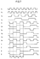
- the test tone circuit 18 includes a timer circuit 19, a first decoder 20, a test tone generator 21, a first switching circuit 22, a second switching circuit 23, a third switching circuit 24, a fourth switching circuit 25 and a second decoder 26.
- the timer circuit 19 includes an oscillator 190 of 30 KHz, a frequency divider 191 which divides the output of the oscillator 190 by 24576 to generate a signal of 1.22 Hz, T-flip-flops 192 and 193, D-flip-flops 194 and 195 and an inverter 196.
- the first decoder 20 includes eight AND gates 200 to 207 and three OR gates 208 to 210. The first decoder 20 decodes timing signals C1 and C2 outputted from the timer circuit 19, to output control signals S1 to S4.
- the first switching circuit 22 is controlled by the control signal S4. This first switching circuit 22 directly outputs a test tone received from the test tone generator 21 when a left or right channel speaker is driven, while attenuating the test tone by -3 dB in an amplifier 220 and outputting the same when a center or surround channel speaker is driven.
- the second and third switching circuits 23 and 24 include buffer amplifiers and switches respectively.
- the second and third switching circuits 23 and 24 are controlled by the control signals S1 and S2 respectively.
- the fourth switching circuit 25 includes an inverter and a switch, and is controlled by the control signal S3.
- the output of the second switching circuit 23 is inputted in an input terminal l of a surround decoder 3 through a third transfer switch 13, while outputs of the third and fourth switching circuits 24 and 25 are coupled with each other and inputted in another input terminal r of the surround decoder 3 through the third transfer switch 13.
- the second decoder 26 includes AND gates 260 to 263. This second decoder 26 decodes the timing signals C1 and C2 outputted from the timer circuit 19, to sequentially derive high outputs at output terminals TL, TC, TR and TS.
- the first decoder 20 decodes the timing signals C1 and C2 outputted from the timer circuit 19, to obtain the control signals S1 to S4.
- the first switching circuit 22 is switched toward contacts a and a in response to the control signal S4.
- the test tone is directly supplied to the second to fourth switching circuits 23 to 25.
- the second switching circuit 23 is closed and the third and fourth switching circuits 24 and 25 are opened.
- the test tone is outputted only at an output terminal l0.
- the first switching circuit 22 is switched toward contacts b and b .
- the test tone is attenuated by -3 dB.
- the second and third switching circuits 23 and 24 are closed and the fourth switching circuit 25 is opened.
- in-phase test tones are outputted at the output terminals l0 and r0.
- the first switching circuit 22 is again switched toward the contacts a and a .
- the test tone is outputted with no attenuation.
- the second switching circuit 23 is opened and the third switching circuit 24 is closed, while the fourth switching circuit 25 is opened.
- the test tone is outputted only at the output terminal r0.
- the first switching circuit 22 is again switched toward the contacts b and b .
- the test tone is attenuated by -3 dB.
- the second switching circuit 23 is closed and the third switching circuit 24 is opened, while the fourth switching circuit 25 is closed.
- opposite-phase test tones are outputted at the output terminals l0 and r0.
- the timing signals C1 and C2 outputted from the timer circuit 19 are also supplied to the second decoder 26.
- high outputs are derived at the output terminals TL, TC, TR and TS in the periods t1, t2, t3 and t4 respectively.
- the outputs are supplied to the microcomputer 14, so that the microcomputer 14 can decide which speaker currently outputs the test tone.
- a CRT displays which speaker currently outputs the test tone by changing the display mode when the user controls the volume levels of the respective speakers in a surround test mode.
- the user can confirm the currently driven speaker and its volume at a glance, to extremely easily control the sound volume. Further, erroneous connection of the speaker can be easily confirmed.
Landscapes
- Physics & Mathematics (AREA)
- Engineering & Computer Science (AREA)
- Acoustics & Sound (AREA)
- Signal Processing (AREA)
- Stereophonic System (AREA)
Claims (13)
- Dispositif de reproduction du son comprenant :(a) un décodeur stéréophonique (3) pour décoder un signal d'entrée et obtenir des signaux de son correspondant à une multitude de canaux;(b) un moyen de commande de volume (4) pour commander les niveaux desdits signaux de son; et(c) une multitude de moyens de régénération du son (6 à 10) prévus en correspondance avec ladite multitude de canaux pour régénérer lesdits signaux de son commandés par ledit moyen de commande de volume (4), respectivement;
ledit dispositif de reproduction du son étant caractérisé par :(d) un moyen de fourniture de signal de test (11) pour fournir des signaux de test d'une fréquence prescrite au décodeur stéréophonique (3);(e) un moyen de commutateur de transfert (13) pour appliquer sélectivement lesdits signaux de son ou lesdits signaux de test audit décodeur stéréophonique;(f) une partie fonction (12) pour commuter ledit moyen de commutateur de transfert; et(g) des moyens de visualisation (14 à 17) pour afficher celui des moyens de régénération de son auquel est généralement appliqué ledit signal de test. - Dispositif de reproduction du son selon la revendication 1, dans lequel :
- lesdits moyens de visualisation (14 à 17) affichent également les niveaux du volume correspondant à ladite multitude de canaux. - Dispositif de reproduction du son selon la revendication 1, dans lequel :
- ladite multitude de moyens de régénération du son est une multitude de moyens de haut-parleur (6 à 10), ledit moyen de fourniture de signal de test est un moyen de fourniture de tonalité de test (11), et ledit signal de test est une tonalité de test. - Dispositif de reproduction du son selon la revendication 3, dans lequel :- ladite multitude de canaux comprend des premier, second, troisième et quatrième canaux,- ledit moyen de fourniture de tonalité de test (11; 18) comporte :- un moyen générateur de tonalité de test (110; 21) pour produire une tonalité de test ayant une fréquence prescrite,- des moyens générateurs de signal de commande (114; 19, 20, 26) pour produire un signal de commande dans un cycle prescrit, et- des moyens de commutation (111 à 113; 22 à 25) pour fournir ladite tonalité de test à ladite multitude de moyens de haut-parleur (6 à 10) par l'intermédiaire dudit moyen de commande de volume lors de chaque période prescrite en réponse audit signal de commande, et
ledit moyen de visualisation comprend :- un moyen de commande (14, 15, 16) pour sortir un signal d'ordre commandant l'affichage du moyen de haut-parleur auquel est généralement appliquée ladite tonalité de test en réponse audit signal de commande provenant dudit moyen générateur de signal de commande, et- une unité de visualisation (17) pour afficher ledit signal d'ordre en réponse audit signal d'ordre provenant dudit moyen de commande (14, 15, 16). - Dispositif de reproduction du son selon la revendication 4, dans lequel ledit moyen de décodeur stéréophonique (3) a des première et seconde bornes d'entrée (ℓ, r) recevant des signaux de son de deux canaux obtenus en décodant des signaux de son de quatre canaux et en décodant lesdits signaux de son de deux canaux pour sortir des signaux de son correspondant à quatre canaux, dans lequel :
- lesdits moyens de commutation (111 à 113) fournissent ladite tonalité de test à ladite première borne d'entrée (ℓ) dudit moyen de décodeur (3) à un premier instant, un signal inversé de ladite tonalité de test auxdites première et seconde bornes d'entrée (ℓ, r) dudit moyen de décodeur (3) à un second instant, ledit signal inversé de ladite tonalité de test à ladite seconde borne d'entrée (r) dudit moyen de décodeur (3) à un troisième instant, et ladite tonalité de test et ledit signal inversé de ladite tonalité de test auxdites première et seconde bornes d'entrée (ℓ, r) dudit moyen de décodeur (3) à un quatrième instant, respectivement. - Dispositif de reproduction du son selon la revendication 4, dans lequel ledit moyen de décodeur stéréophonique (3) comporte des première et seconde bornes d'entrée (ℓ, r) recevant des signaux de son de deux canaux obtenus en codant des signaux de son de quatre canaux et en décodant lesdits signaux de son de deux canaux afin de sortir des signaux de son correspondant à quatre canaux, dans lequel :
- lesdits moyens de commutation (22 à 25) fournissent ladite tonalité de test à ladite première borne d'entrée (ℓ) dudit moyen de décodeur (3) à un premier instant, un signal obtenu en atténuant ladite tonalité de test auxdites première et seconde bornes d'entrée (ℓ, r) dudit moyen de décodeur (3) à un second instant, ladite tonalité de test à ladite seconde borne d'entrée (r) dudit moyen de décodeur (3) à un troisième instant, et ledit signal obtenu en atténuant ladite tonalité de test et un signal inversé dudit signal obtenu en atténuant ladite tonalité de test auxdites première et seconde bornes d'entrée (ℓ, r) dudit moyen de décodeur (3) à un quatrième instant, respectivement. - Dispositif de reproduction du son selon la revendication 4, dans lequel :- ledit moyen générateur de signal de commande (114; 19, 20, 26) comprend :- un moyen de minuterie (19) pour produire une paire de signaux de minutage ayant des cycles différents,- un premier décodeur (20) pour décoder lesdits signaux de minutage et produire une multitude de premiers signaux de commande, et- un second décodeur (26) pour décoder lesdits signaux de minutage et produire une multitude de seconds signaux de commande correspondant auxdits quatre canaux, et- lesdits moyens de commande (14 à 16) pour faire en sorte que lesdits moyens de haut-parleur reçoivent généralement ladite tonalité de test affichée sur ladite unité de visualisation (17) en réponse auxdits seconds signaux de commande provenant dudit second décodeur (26).
- Dispositif de reproduction du son selon la revendication 4, dans lequel :
- lesdits moyens de commande (14 à 16) permettent un affichage correspondant au moyen de haut-parleur recevant généralement ladite tonalité de test différente de celle correspondant aux autres desdits moyens de haut-parleur. - Dispositif de reproduction du son selon la revendication 5, comportant en outre un premier moyen de commutation (13) pour fournir soit lesdits signaux de son reçus des deux canaux soit ladite tonalité de test audit moyen de décodeur (3).
- Dispositif de reproduction du son selon la revendication 6, comportant en outre un premier moyen de commutation (13) pour fournir soit lesdits signaux de son reçus des deux canaux soit ladite tonalité de test audit moyen de décodeur (3).
- Récepteur de télévision ayant un écran de télévision (17) et reproduisant des signaux de son correspondant à une multitude de canaux, comprenant :(a) un décodeur stéréophonique (3) pour décoder un signal d'entrée en signaux de son correspondant à une multitude de canaux;(b) un moyen de commande de volume (4) pour commander les niveaux desdits signaux de son; et(c) une multitude de moyens régénérateurs de son (6 à 10) fournis en correspondance avec ladite multitude de canaux pour régénérer lesdits signaux de son commandés par ledit moyen de commande de volume (4), respectivement;
ledit récepteur de télévision étant caractérisé par :(d) un moyen de fourniture de signal de test (11) pour fournir les signaux d'une fréquence prescrite au décodeur stéréophonique (3);(e) un moyen de commutateur de transfert (13) pour appliquer sélectivement lesdits signaux de son ou lesdits signaux de test audit décodeur stéréophonique;(f) une partie fonction (12) pour faire commuter ledit moyen de commutateur de transfert; et(g) des moyens de visualisation (14 à 16) pour afficher celui des moyen de haut-parleur qui reçoit généralement ladite tonalité de test sur ledit écran de télévision (17). - Récepteur de télévision selon la revendication 11, dans lequel :
- lesdits moyens de visualisation (14 à 16) affichent en outre les niveaux du volume correspondant à ladite multitude de canaux sur ledit écran de télévision (17). - Récepteur de télévision selon la revendication 12, dans lequel :- ladite multitude de canaux comprend des premier, second, troisième et quatrième canaux,- ledit moyen de fourniture de tonalité de test (11; 18) comprend :- un moyen générateur de tonalité de test (110; 21) pour produire une tonalité de test d'une fréquence prescrite,- un moyen générateur de signal de commande (114; 19, 20, 26) pour produire un signal de commande dans un cycle prescrit, et- des moyens de commutation (111 à 113; 22 à 25) pour fournir ladite tonalité de test à ladite multitude de moyens de haut-parleur (6 à 10) par l'intermédiaire dudit moyen de commande de volume (4) lors de chaque période prescrite en réponse audit signal de commande, et
ledit moyen de visualisation comprend des moyen de commande (14 à 16) pour permettre un affichage indiquant le haut-parleur recevant généralement ladite tonalité de test sur ledit écran de télévision (17) en réponse audit signal de commande provenant dudit moyen générateur de signal de commande (114; 19, 20, 26).
Priority Applications (1)
| Application Number | Priority Date | Filing Date | Title |
|---|---|---|---|
| EP92112188A EP0516183B1 (fr) | 1988-07-20 | 1989-07-19 | Récepteur de télévision |
Applications Claiming Priority (6)
| Application Number | Priority Date | Filing Date | Title |
|---|---|---|---|
| JP96021/88U | 1988-07-20 | ||
| JP9602188 | 1988-07-20 | ||
| JP18051288 | 1988-07-20 | ||
| JP180512/88 | 1988-07-20 | ||
| JP1151984A JPH02131700A (ja) | 1988-07-20 | 1989-06-13 | テレビジョン受像機 |
| JP151984/89 | 1989-06-13 |
Related Child Applications (2)
| Application Number | Title | Priority Date | Filing Date |
|---|---|---|---|
| EP92112188A Division EP0516183B1 (fr) | 1988-07-20 | 1989-07-19 | Récepteur de télévision |
| EP92112188.5 Division-Into | 1992-07-16 |
Publications (3)
| Publication Number | Publication Date |
|---|---|
| EP0352627A2 EP0352627A2 (fr) | 1990-01-31 |
| EP0352627A3 EP0352627A3 (fr) | 1992-01-02 |
| EP0352627B1 true EP0352627B1 (fr) | 1995-03-08 |
Family
ID=27307982
Family Applications (1)
| Application Number | Title | Priority Date | Filing Date |
|---|---|---|---|
| EP89113282A Expired - Lifetime EP0352627B1 (fr) | 1988-07-20 | 1989-07-19 | Reproducteur de son |
Country Status (4)
| Country | Link |
|---|---|
| US (1) | US4933768A (fr) |
| EP (1) | EP0352627B1 (fr) |
| CA (1) | CA1312369C (fr) |
| DE (2) | DE68926249T2 (fr) |
Families Citing this family (37)
| Publication number | Priority date | Publication date | Assignee | Title |
|---|---|---|---|---|
| JPS63183495A (ja) * | 1987-01-27 | 1988-07-28 | ヤマハ株式会社 | 音場制御装置 |
| US5077797A (en) * | 1989-05-25 | 1991-12-31 | Sanyo Electric Co., Ltd. | Fm stereo receiver |
| US5212733A (en) * | 1990-02-28 | 1993-05-18 | Voyager Sound, Inc. | Sound mixing device |
| US5666424A (en) * | 1990-06-08 | 1997-09-09 | Harman International Industries, Inc. | Six-axis surround sound processor with automatic balancing and calibration |
| US5257313A (en) * | 1990-07-09 | 1993-10-26 | Sony Corporation | Surround audio apparatus |
| JPH0453400U (fr) * | 1990-09-13 | 1992-05-07 | ||
| JPH04150200A (ja) * | 1990-10-09 | 1992-05-22 | Yamaha Corp | 音場制御装置 |
| US5309517A (en) * | 1991-05-17 | 1994-05-03 | Crown International, Inc. | Audio multiplexer |
| US5590207A (en) * | 1993-12-14 | 1996-12-31 | Taylor Group Of Companies, Inc. | Sound reproducing array processor system |
| US5745584A (en) * | 1993-12-14 | 1998-04-28 | Taylor Group Of Companies, Inc. | Sound bubble structures for sound reproducing arrays |
| US5517570A (en) * | 1993-12-14 | 1996-05-14 | Taylor Group Of Companies, Inc. | Sound reproducing array processor system |
| US6240189B1 (en) * | 1994-06-08 | 2001-05-29 | Bose Corporation | Generating a common bass signal |
| DE4435224A1 (de) * | 1994-09-30 | 1996-04-04 | Nokia Deutschland Gmbh | Tonwiedergabeanordnung |
| DE4440014C2 (de) * | 1994-11-09 | 2002-02-07 | Deutsche Telekom Ag | Verfahren und Vorrichtung zur mehrkanaligen Tonwiedergabe |
| FR2728753A1 (fr) * | 1994-12-21 | 1996-06-28 | Grenier Yves | Dispositif de prise de sons comprenant un systeme video pour le reglage de parametres et procede de reglage |
| JP2956545B2 (ja) * | 1995-08-28 | 1999-10-04 | ヤマハ株式会社 | 音場制御装置 |
| DE59611437D1 (de) * | 1996-02-27 | 2007-08-23 | Micronas Gmbh | Schaltung zur Dekodierung einer Zusatzinformation in einer Rundfunkübertragung |
| US6111959A (en) * | 1996-10-31 | 2000-08-29 | Taylor Group Of Companies, Inc. | Sound spreader |
| US5912976A (en) * | 1996-11-07 | 1999-06-15 | Srs Labs, Inc. | Multi-channel audio enhancement system for use in recording and playback and methods for providing same |
| JP4478220B2 (ja) | 1997-05-29 | 2010-06-09 | ソニー株式会社 | 音場補正回路 |
| WO1999011100A1 (fr) * | 1997-08-26 | 1999-03-04 | Koninklijke Philips Electronics N.V. | Procede de definition de parametres concernant des signaux |
| KR20010006291A (ko) * | 1998-02-13 | 2001-01-26 | 요트.게.아. 롤페즈 | 서라운드 음향 재생 시스템, 음향/시각 재생 시스템, 서라운드 신호 처리 유닛 및 입력 서라운드 신호 처리 방법 |
| US6977653B1 (en) * | 2000-03-08 | 2005-12-20 | Tektronix, Inc. | Surround sound display |
| JP4215967B2 (ja) * | 2001-05-29 | 2009-01-28 | パイオニア株式会社 | 音響装置 |
| US7164768B2 (en) | 2001-06-21 | 2007-01-16 | Bose Corporation | Audio signal processing |
| US20050185806A1 (en) | 2003-02-14 | 2005-08-25 | Salvador Eduardo T. | Controlling fading and surround signal level |
| US7305097B2 (en) | 2003-02-14 | 2007-12-04 | Bose Corporation | Controlling fading and surround signal level |
| US20050058307A1 (en) * | 2003-07-12 | 2005-03-17 | Samsung Electronics Co., Ltd. | Method and apparatus for constructing audio stream for mixing, and information storage medium |
| KR100604016B1 (ko) * | 2003-08-11 | 2006-07-24 | 엘지전자 주식회사 | 소리레벨 제어 기능을 갖는 영상표시기기 및 그 제어방법 |
| DE10354492A1 (de) * | 2003-11-21 | 2005-06-09 | Volkswagen Ag | Einstelleinrichtung für eine Lautsprecheranlage in einem Fahrzeug sowie entsprechendes Einstellverfahren |
| JP3852452B2 (ja) * | 2004-03-16 | 2006-11-29 | ソニー株式会社 | 画像データ保存方法及び画像処理装置 |
| JP4568536B2 (ja) * | 2004-03-17 | 2010-10-27 | ソニー株式会社 | 測定装置、測定方法、プログラム |
| US8050434B1 (en) | 2006-12-21 | 2011-11-01 | Srs Labs, Inc. | Multi-channel audio enhancement system |
| US8274611B2 (en) * | 2008-06-27 | 2012-09-25 | Mitsubishi Electric Visual Solutions America, Inc. | System and methods for television with integrated sound projection system |
| US8279357B2 (en) * | 2008-09-02 | 2012-10-02 | Mitsubishi Electric Visual Solutions America, Inc. | System and methods for television with integrated sound projection system |
| JP5515389B2 (ja) * | 2009-04-22 | 2014-06-11 | ソニー株式会社 | オーディオ処理装置及びオーディオ処理方法 |
| JP5955862B2 (ja) | 2011-01-04 | 2016-07-20 | ディーティーエス・エルエルシーDts Llc | 没入型オーディオ・レンダリング・システム |
Family Cites Families (8)
| Publication number | Priority date | Publication date | Assignee | Title |
|---|---|---|---|---|
| US4385814A (en) * | 1980-06-25 | 1983-05-31 | Paramount Sound Systems Corporation | System for controlling distinct devices in a theater |
| US4577188A (en) * | 1981-09-03 | 1986-03-18 | Victor Company Of Japan, Ltd. | Level display device for audio signal |
| GB2118407B (en) * | 1982-03-31 | 1985-09-11 | Thorn Emi Ferguson | Television reciever |
| US4589129A (en) * | 1984-02-21 | 1986-05-13 | Kintek, Inc. | Signal decoding system |
| US4799260A (en) * | 1985-03-07 | 1989-01-17 | Dolby Laboratories Licensing Corporation | Variable matrix decoder |
| US4696036A (en) * | 1985-09-12 | 1987-09-22 | Shure Brothers, Inc. | Directional enhancement circuit |
| US4817149A (en) * | 1987-01-22 | 1989-03-28 | American Natural Sound Company | Three-dimensional auditory display apparatus and method utilizing enhanced bionic emulation of human binaural sound localization |
| JPS63183495A (ja) * | 1987-01-27 | 1988-07-28 | ヤマハ株式会社 | 音場制御装置 |
-
1989
- 1989-07-19 DE DE68926249T patent/DE68926249T2/de not_active Expired - Fee Related
- 1989-07-19 EP EP89113282A patent/EP0352627B1/fr not_active Expired - Lifetime
- 1989-07-19 US US07/381,923 patent/US4933768A/en not_active Expired - Lifetime
- 1989-07-19 DE DE68921517T patent/DE68921517T2/de not_active Expired - Fee Related
- 1989-07-19 CA CA000606078A patent/CA1312369C/fr not_active Expired - Lifetime
Also Published As
| Publication number | Publication date |
|---|---|
| US4933768A (en) | 1990-06-12 |
| EP0352627A3 (fr) | 1992-01-02 |
| DE68921517T2 (de) | 1996-01-25 |
| DE68926249T2 (de) | 1996-11-28 |
| CA1312369C (fr) | 1993-01-05 |
| EP0352627A2 (fr) | 1990-01-31 |
| DE68926249D1 (de) | 1996-05-15 |
| DE68921517D1 (de) | 1995-04-13 |
Similar Documents
| Publication | Publication Date | Title |
|---|---|---|
| EP0352627B1 (fr) | Reproducteur de son | |
| US7668317B2 (en) | Audio post processing in DVD, DTV and other audio visual products | |
| KR100682490B1 (ko) | 오디오신호처리장치 및 오디오장치 | |
| US5237418A (en) | Audio output circuit in electronic apparatus with composite display function | |
| US5680464A (en) | Sound field controlling device | |
| JPH03270600A (ja) | オーディオ再生装置 | |
| US5197099A (en) | Multiple-channel audio reproduction apparatus | |
| US5261005A (en) | Sound field control device | |
| CN101276588B (zh) | 用于输出音频信号的方法以及音频解码器 | |
| US7212253B1 (en) | Home entertainment system audio handling | |
| EP0516183B1 (fr) | Récepteur de télévision | |
| US5987141A (en) | Stereo expander | |
| US7502477B1 (en) | Audio reproducing apparatus | |
| JPH02131700A (ja) | テレビジョン受像機 | |
| JPH03258176A (ja) | テレビジョン受像機 | |
| US5123051A (en) | Sound field reproducing apparatus | |
| EP0630168A1 (fr) | Décodeur prologic Dolby | |
| EP1750476A2 (fr) | Appareil audio et procédé de commande | |
| JPH09130898A (ja) | オーディオ機器 | |
| EP1471771A2 (fr) | Appareil de reproduction audio et récepteur vidéo | |
| KR20000002810U (ko) | 입체 음향기기의 음향모드 자동 선택장치 | |
| KR100276448B1 (ko) | 큐 스테레오 사운드 증가방법 | |
| JPH0744159Y2 (ja) | カラ−テレビジョン受像機 | |
| JP2000125400A (ja) | 映像音響装置 | |
| JPH1118016A (ja) | 音声信号入力端子を有する映像装置 |
Legal Events
| Date | Code | Title | Description |
|---|---|---|---|
| PUAI | Public reference made under article 153(3) epc to a published international application that has entered the european phase |
Free format text: ORIGINAL CODE: 0009012 |
|
| AK | Designated contracting states |
Kind code of ref document: A2 Designated state(s): DE FR GB |
|
| 17P | Request for examination filed |
Effective date: 19901228 |
|
| PUAL | Search report despatched |
Free format text: ORIGINAL CODE: 0009013 |
|
| AK | Designated contracting states |
Kind code of ref document: A3 Designated state(s): DE FR GB |
|
| 17Q | First examination report despatched |
Effective date: 19930927 |
|
| GRAA | (expected) grant |
Free format text: ORIGINAL CODE: 0009210 |
|
| AK | Designated contracting states |
Kind code of ref document: B1 Designated state(s): DE FR GB |
|
| XX | Miscellaneous (additional remarks) |
Free format text: TEILANMELDUNG 92112188.5 EINGEREICHT AM 19/07/89. |
|
| REF | Corresponds to: |
Ref document number: 68921517 Country of ref document: DE Date of ref document: 19950413 |
|
| ET | Fr: translation filed | ||
| PLBE | No opposition filed within time limit |
Free format text: ORIGINAL CODE: 0009261 |
|
| STAA | Information on the status of an ep patent application or granted ep patent |
Free format text: STATUS: NO OPPOSITION FILED WITHIN TIME LIMIT |
|
| 26N | No opposition filed | ||
| REG | Reference to a national code |
Ref country code: GB Ref legal event code: IF02 |
|
| PGFP | Annual fee paid to national office [announced via postgrant information from national office to epo] |
Ref country code: DE Payment date: 20070712 Year of fee payment: 19 |
|
| PGFP | Annual fee paid to national office [announced via postgrant information from national office to epo] |
Ref country code: GB Payment date: 20070718 Year of fee payment: 19 |
|
| PGFP | Annual fee paid to national office [announced via postgrant information from national office to epo] |
Ref country code: FR Payment date: 20070710 Year of fee payment: 19 |
|
| GBPC | Gb: european patent ceased through non-payment of renewal fee |
Effective date: 20080719 |
|
| PG25 | Lapsed in a contracting state [announced via postgrant information from national office to epo] |
Ref country code: DE Free format text: LAPSE BECAUSE OF NON-PAYMENT OF DUE FEES Effective date: 20090203 |
|
| REG | Reference to a national code |
Ref country code: FR Ref legal event code: ST Effective date: 20090331 |
|
| PG25 | Lapsed in a contracting state [announced via postgrant information from national office to epo] |
Ref country code: GB Free format text: LAPSE BECAUSE OF NON-PAYMENT OF DUE FEES Effective date: 20080719 |
|
| PG25 | Lapsed in a contracting state [announced via postgrant information from national office to epo] |
Ref country code: FR Free format text: LAPSE BECAUSE OF NON-PAYMENT OF DUE FEES Effective date: 20080731 |