EP0352648B1 - Methode und Anlage zur Herstellung von bituminösem Mischgut für Decken - Google Patents
Methode und Anlage zur Herstellung von bituminösem Mischgut für Decken Download PDFInfo
- Publication number
- EP0352648B1 EP0352648B1 EP89113397A EP89113397A EP0352648B1 EP 0352648 B1 EP0352648 B1 EP 0352648B1 EP 89113397 A EP89113397 A EP 89113397A EP 89113397 A EP89113397 A EP 89113397A EP 0352648 B1 EP0352648 B1 EP 0352648B1
- Authority
- EP
- European Patent Office
- Prior art keywords
- drum
- mixing
- aggregate
- section
- plant
- Prior art date
- Legal status (The legal status is an assumption and is not a legal conclusion. Google has not performed a legal analysis and makes no representation as to the accuracy of the status listed.)
- Expired - Lifetime
Links
- 239000000203 mixture Substances 0.000 title claims abstract description 78
- 238000000034 method Methods 0.000 title claims description 21
- 239000000463 material Substances 0.000 claims abstract description 118
- 239000010426 asphalt Substances 0.000 claims abstract description 36
- 238000001035 drying Methods 0.000 claims abstract description 25
- 238000004519 manufacturing process Methods 0.000 claims abstract description 16
- 239000011230 binding agent Substances 0.000 claims abstract description 13
- 238000005192 partition Methods 0.000 claims description 28
- 239000004576 sand Substances 0.000 claims description 17
- 238000010438 heat treatment Methods 0.000 claims description 7
- 230000001154 acute effect Effects 0.000 claims description 6
- 238000007599 discharging Methods 0.000 claims description 4
- 230000002093 peripheral effect Effects 0.000 claims description 3
- 230000008859 change Effects 0.000 claims description 2
- 238000010924 continuous production Methods 0.000 abstract description 2
- 239000000654 additive Substances 0.000 description 22
- 239000004575 stone Substances 0.000 description 15
- 239000000945 filler Substances 0.000 description 14
- 230000008569 process Effects 0.000 description 9
- 239000000446 fuel Substances 0.000 description 6
- 239000000567 combustion gas Substances 0.000 description 5
- 239000000523 sample Substances 0.000 description 5
- 239000000126 substance Substances 0.000 description 5
- 239000002994 raw material Substances 0.000 description 4
- 230000000717 retained effect Effects 0.000 description 4
- 238000005303 weighing Methods 0.000 description 4
- 230000006870 function Effects 0.000 description 3
- 238000005259 measurement Methods 0.000 description 3
- 239000007787 solid Substances 0.000 description 3
- 235000008733 Citrus aurantifolia Nutrition 0.000 description 2
- 239000004150 EU approved colour Substances 0.000 description 2
- 235000011941 Tilia x europaea Nutrition 0.000 description 2
- 230000004888 barrier function Effects 0.000 description 2
- 239000003795 chemical substances by application Substances 0.000 description 2
- 238000002485 combustion reaction Methods 0.000 description 2
- 239000000428 dust Substances 0.000 description 2
- 230000000694 effects Effects 0.000 description 2
- 239000004571 lime Substances 0.000 description 2
- 239000007788 liquid Substances 0.000 description 2
- 230000007257 malfunction Effects 0.000 description 2
- 229940006093 opthalmologic coloring agent diagnostic Drugs 0.000 description 2
- 238000004064 recycling Methods 0.000 description 2
- 238000012546 transfer Methods 0.000 description 2
- UGFAIRIUMAVXCW-UHFFFAOYSA-N Carbon monoxide Chemical compound [O+]#[C-] UGFAIRIUMAVXCW-UHFFFAOYSA-N 0.000 description 1
- 238000005452 bending Methods 0.000 description 1
- 238000011437 continuous method Methods 0.000 description 1
- 238000012937 correction Methods 0.000 description 1
- 238000013461 design Methods 0.000 description 1
- 239000003546 flue gas Substances 0.000 description 1
- 230000004907 flux Effects 0.000 description 1
- 239000004816 latex Substances 0.000 description 1
- 229920000126 latex Polymers 0.000 description 1
- 238000012986 modification Methods 0.000 description 1
- 230000004048 modification Effects 0.000 description 1
- 238000012544 monitoring process Methods 0.000 description 1
- 239000002245 particle Substances 0.000 description 1
- 239000000049 pigment Substances 0.000 description 1
- 238000000926 separation method Methods 0.000 description 1
- 238000011144 upstream manufacturing Methods 0.000 description 1
Images


Classifications
-
- E—FIXED CONSTRUCTIONS
- E01—CONSTRUCTION OF ROADS, RAILWAYS, OR BRIDGES
- E01C—CONSTRUCTION OF, OR SURFACES FOR, ROADS, SPORTS GROUNDS, OR THE LIKE; MACHINES OR AUXILIARY TOOLS FOR CONSTRUCTION OR REPAIR
- E01C19/00—Machines, tools or auxiliary devices for preparing or distributing paving materials, for working the placed materials, or for forming, consolidating, or finishing the paving
- E01C19/02—Machines, tools or auxiliary devices for preparing or distributing paving materials, for working the placed materials, or for forming, consolidating, or finishing the paving for preparing the materials
- E01C19/10—Apparatus or plants for premixing or precoating aggregate or fillers with non-hydraulic binders, e.g. with bitumen, with resins, i.e. producing mixtures or coating aggregates otherwise than by penetrating or surface dressing; Apparatus for premixing non-hydraulic mixtures prior to placing or for reconditioning salvaged non-hydraulic compositions
- E01C19/1004—Reconditioning or reprocessing bituminous mixtures, e.g. salvaged paving, fresh patching mixtures grown unserviceable; Recycling salvaged bituminous mixtures; Apparatus for the in-plant recycling thereof
-
- E—FIXED CONSTRUCTIONS
- E01—CONSTRUCTION OF ROADS, RAILWAYS, OR BRIDGES
- E01C—CONSTRUCTION OF, OR SURFACES FOR, ROADS, SPORTS GROUNDS, OR THE LIKE; MACHINES OR AUXILIARY TOOLS FOR CONSTRUCTION OR REPAIR
- E01C19/00—Machines, tools or auxiliary devices for preparing or distributing paving materials, for working the placed materials, or for forming, consolidating, or finishing the paving
- E01C19/02—Machines, tools or auxiliary devices for preparing or distributing paving materials, for working the placed materials, or for forming, consolidating, or finishing the paving for preparing the materials
- E01C19/10—Apparatus or plants for premixing or precoating aggregate or fillers with non-hydraulic binders, e.g. with bitumen, with resins, i.e. producing mixtures or coating aggregates otherwise than by penetrating or surface dressing; Apparatus for premixing non-hydraulic mixtures prior to placing or for reconditioning salvaged non-hydraulic compositions
- E01C19/1013—Plant characterised by the mode of operation or the construction of the mixing apparatus; Mixing apparatus
- E01C19/1027—Mixing in a rotary receptacle
- E01C19/1031—Mixing in a rotary receptacle the mixture being discharged continuously
-
- E—FIXED CONSTRUCTIONS
- E01—CONSTRUCTION OF ROADS, RAILWAYS, OR BRIDGES
- E01C—CONSTRUCTION OF, OR SURFACES FOR, ROADS, SPORTS GROUNDS, OR THE LIKE; MACHINES OR AUXILIARY TOOLS FOR CONSTRUCTION OR REPAIR
- E01C19/00—Machines, tools or auxiliary devices for preparing or distributing paving materials, for working the placed materials, or for forming, consolidating, or finishing the paving
- E01C19/02—Machines, tools or auxiliary devices for preparing or distributing paving materials, for working the placed materials, or for forming, consolidating, or finishing the paving for preparing the materials
- E01C19/10—Apparatus or plants for premixing or precoating aggregate or fillers with non-hydraulic binders, e.g. with bitumen, with resins, i.e. producing mixtures or coating aggregates otherwise than by penetrating or surface dressing; Apparatus for premixing non-hydraulic mixtures prior to placing or for reconditioning salvaged non-hydraulic compositions
- E01C19/1013—Plant characterised by the mode of operation or the construction of the mixing apparatus; Mixing apparatus
- E01C19/1027—Mixing in a rotary receptacle
- E01C19/1036—Mixing in a rotary receptacle for in-plant recycling or for reprocessing, e.g. adapted to receive and reprocess an addition of salvaged material, adapted to reheat and remix cooled-down batches
-
- E—FIXED CONSTRUCTIONS
- E01—CONSTRUCTION OF ROADS, RAILWAYS, OR BRIDGES
- E01C—CONSTRUCTION OF, OR SURFACES FOR, ROADS, SPORTS GROUNDS, OR THE LIKE; MACHINES OR AUXILIARY TOOLS FOR CONSTRUCTION OR REPAIR
- E01C19/00—Machines, tools or auxiliary devices for preparing or distributing paving materials, for working the placed materials, or for forming, consolidating, or finishing the paving
- E01C19/02—Machines, tools or auxiliary devices for preparing or distributing paving materials, for working the placed materials, or for forming, consolidating, or finishing the paving for preparing the materials
- E01C19/10—Apparatus or plants for premixing or precoating aggregate or fillers with non-hydraulic binders, e.g. with bitumen, with resins, i.e. producing mixtures or coating aggregates otherwise than by penetrating or surface dressing; Apparatus for premixing non-hydraulic mixtures prior to placing or for reconditioning salvaged non-hydraulic compositions
- E01C19/1059—Controlling the operations; Devices solely for supplying or proportioning the ingredients
- E01C19/1063—Controlling the operations
-
- E—FIXED CONSTRUCTIONS
- E01—CONSTRUCTION OF ROADS, RAILWAYS, OR BRIDGES
- E01C—CONSTRUCTION OF, OR SURFACES FOR, ROADS, SPORTS GROUNDS, OR THE LIKE; MACHINES OR AUXILIARY TOOLS FOR CONSTRUCTION OR REPAIR
- E01C19/00—Machines, tools or auxiliary devices for preparing or distributing paving materials, for working the placed materials, or for forming, consolidating, or finishing the paving
- E01C19/02—Machines, tools or auxiliary devices for preparing or distributing paving materials, for working the placed materials, or for forming, consolidating, or finishing the paving for preparing the materials
- E01C19/10—Apparatus or plants for premixing or precoating aggregate or fillers with non-hydraulic binders, e.g. with bitumen, with resins, i.e. producing mixtures or coating aggregates otherwise than by penetrating or surface dressing; Apparatus for premixing non-hydraulic mixtures prior to placing or for reconditioning salvaged non-hydraulic compositions
- E01C19/1059—Controlling the operations; Devices solely for supplying or proportioning the ingredients
- E01C19/1068—Supplying or proportioning the ingredients
-
- E—FIXED CONSTRUCTIONS
- E01—CONSTRUCTION OF ROADS, RAILWAYS, OR BRIDGES
- E01C—CONSTRUCTION OF, OR SURFACES FOR, ROADS, SPORTS GROUNDS, OR THE LIKE; MACHINES OR AUXILIARY TOOLS FOR CONSTRUCTION OR REPAIR
- E01C19/00—Machines, tools or auxiliary devices for preparing or distributing paving materials, for working the placed materials, or for forming, consolidating, or finishing the paving
- E01C19/02—Machines, tools or auxiliary devices for preparing or distributing paving materials, for working the placed materials, or for forming, consolidating, or finishing the paving for preparing the materials
- E01C19/10—Apparatus or plants for premixing or precoating aggregate or fillers with non-hydraulic binders, e.g. with bitumen, with resins, i.e. producing mixtures or coating aggregates otherwise than by penetrating or surface dressing; Apparatus for premixing non-hydraulic mixtures prior to placing or for reconditioning salvaged non-hydraulic compositions
- E01C2019/1081—Details not otherwise provided for
- E01C2019/1095—Mixing containers having a parallel flow drum, i.e. the flow of material is parallel to the gas flow
Definitions
- the present invention relates to a method of producing a bituminous or asphalt paving mixture.
- bituminous paving mixture has been produced by either one of two different methods, namely the so-called “batch-mixing” and the so-called “drum-mixing”, respectively.
- Batch-mixing is a discontinuous method of production which is suitable for use in connection with production plants from which relatively small amounts of a bituminous or asphalt mixture of varying, further specified compositions are to be delivered during a day to many different purchasers.
- stone and sand fractions are metered according to the purchaser's recipe or specifications by means of metering apparatus, and the materials so metered are transported to a drying drum where the materials are dried and heated to a temperature of about 160-180°C.
- the materials are sieved into 4-6 fractions and stored in a hot silo or buffer silo. From the hot silos a portion or batch of 2000-4000 kg is weighed out, and filler, bitumen and other additives are weighed out as a certain percentage of the stone and sand material according to the recipe presented. When all components have been weighed out, the materials are mixed for about 30-50 seconds in a special mixing apparatus. The mixture is now ready for use and may be transported to a product silo where it may be collected by the purchaser.
- Drum-mixing is a continuous method of production which is suitable for use in connection with production plants from which large amounts of bituminous or asphalt paving mixtures of rather uniform compositions are to be supplied, for example in connection with large civil engineering projects or for purchasers of large asphalt mixture amounts.
- aggregate such as stone and sand fractions are metered continuously in accordance with a recipe or specifications by means of metering apparatus, and the metered materials are continuously passed to a drying drum through which they may flow substantially continuously.
- the materials are dried and heated to a temperature of 160-180°, and in the last part of the drum, filler, bitumen and any additives are continuously added.
- the dried and heated materials are mixed with the additives in the last part of the drum so that finished mixture is discharged continuously from the outlet end of the drum.
- the invention provides a method which renders it possible to produce large amounts as well as relatively small amounts of paving mixture of different compositions in a rational manner in the same plant.
- the method according to the invention comprises supplying aggregate, for example sand and/or gravel, into a first section of a rotating drying and mixing drum at an inlet end thereof, introducing at least one further component, for example a binder, such as bitumen and/or recycled material into a second section of the drum between said inlet end and an opposite outlet end of the drum, mixing said component with the dried aggregate in the drum, and discharging the mixture at the other end of the drum, and the method according to the invention is characterized by the steps of supplying the aggregate to the drum in portions, drying each portion in said first drum section, transferring a first portion to the second drum section after drying such portion and prior to supplying a second portion of aggregate into the drum, and mixing the dried first portion of aggregate with said further component in said second drum section, while said first and second portions are kept substantially apart in the drum.
- aggregate for example sand and/or gravel
- drum sections are normally longitudinal sections of one and the same drum, but, alternatively, the drum may be formed as a drum unit composed by separate drum sections connected in series.
- the dried aggregate portions may be transferred from one section to the other in any suitable manner.
- the aggregate portions may, for example, be pushed from one section to the other by means of some kind of automatically operating pushing means arranged inside the drum.
- the transfer of the dried aggregate portions from one section to another section and possibly also discharging the bituminous mixture from the drum is preferably effected by tilting the drum and/or by increasing the rotational speed of the drum.
- the tilting may, for example, be effected by supporting one end of the drum by lifting means, for example mechanical jacks or hydraulic or pneumatic cylinders which are adapted to selectively lift or lower one end of the drum.
- the drum axis may be horizontal or may define a small acute angle with a horizontal plane in an upward or downward direction, and when a dried aggregate portion is to be displaced from one drum section to another, this may be effected by lifting one end of the drum so that the aggregate portion may slide forward to the next drum section, while a finished mixture portion may possibly simultaneously be discharged from the drum.
- barriers are arranged to ensure that the portions being treated simultaneously in the drum are kept apart. These barriers may, for example, be in the form of projections or ribs formed on the inner wall of the drum. These projections form an annular, radially inwardly extending partition wall which may be opened when a portion is to be transferred from one drum section to another.
- Such a partition wall may, for example, be formed by a number of ring sectors which are mounted in the drum wall in such a manner that they may be rotated about substantially radial axes. When a material portion is to be transferred, these ring sectors may be rotated from a position in which they are at substantially right angles to the drum axis into a position in which they extend substantially parallelly therewith.
- an end wall may be arranged at the outlet end of the drum. Such an end wall may be moved into an open position in case of drum-mixing, or when a portion of finished mixture is to be discharged from the drum in case of batch-mixing.
- the invention also relates to a drying and mixing plant for the production of a bituminous paving mixture, said plant comprising a drying and mixing drum having inlet and outlet ends, driving means for rotating the drum about its longitudinal axis, means for feeding aggregate into the drum at its inlet end, means for supplying a further component, such as a binder, into the drum at locations intermediate of the inlet and outlet ends, and inclination adjustment means for lifting and lowering the drum so as to change the inclination of the drum axis, said plant being characterized as that closure means for selectively at least partly closing and opening the outlet end of the drum are provided, and in that the drum is divided into sections by at least one annular partition wall extending radially inward from the inner wall of the drum, said partition wall being selectively movable between a position in which flow of material between adjacent drum sections is obstructed and a position in which material may flow freely from one section to another.
- Such a drum which is suitable for drum-mixing may then also be used for batch-mixing, as the aggregate may be introduced into the drum in portions which may then be transferred from one drum section to another or be poured out of the drum by tilting the drum by means of the inclination adjustment means, when the closure means are open.
- the inclination adjustment means may, for example, be in the form of mechanical jacks or pneumatic or hydraulic cylinders. The transfer and the pouring out of the portions of material may be speeded up by increasing the rotational speed of the drum and thus the material transportation velocity.
- the end closure means may, for example, comprise an end wall which is operated by means of hydraulic or pneumatic cylinders, screw spindles or other mechanical moving means.
- Such end wall may be movable between a closed position in which the end wall is closely adjacent to and at least partly closes the outlet end of the drum, and an open position in which the end wall is spaced from the outlet end so that the latter is open.
- the outlet end of the drum In batch-mixing the outlet end of the drum is normally kept closed by means of the movable end wall and is opened only when a portion of finished mixture is to be discharged from the drum.
- the end wall In case of drum-mixing, however, the end wall is constantly kept in its open position. However, if the closure means or end wall in its closed position closes the drum end only partly, the closure means may remain closed even in case of drum-mixing.
- the aggregate introduced into the drying and mixing drum may, in principle, be dried by supply of heat from heating means of any type or from any suitable heat source.
- these heating means comprise at least one burner directed into the drum. If the burner is adjusted so that an optimum heat economy is obtained in drum-mixing and at a certain continuous flow of material, it will not be possible to obtain such an optimum heat economy for all sizes of portions of raw material supplied to the drum when the same drum is used for a batch-mixing process.
- the burner may be mounted in such a manner that its direction may be altered, for example in the horizontal as well as in the vertical direction, and the direction of the burner may then be adjusted so that the best possible heat exploitation is obtained at each individual portion size.
- the position of the burner inside the drum may also optionally be changed, and the burner capacity may likewise be adjusted as desired.
- the drum may be divided into sections by at least one annular partition wall extending radially inwardly from the inner wall of the drum, said partition wall being selectively movable between a position in which flow of material between adjacent drum sections is obstructed and a position in which material may flow freely from one section to another.
- the partition wall When the drum is used for batch-mixing, the partition wall is normally in its closed position and then serves to divide the drum into sections and to keep apart the individual material portions being simultaneously treated in the drum. However, the partition wall may be opened when the material portions are to be transferred from one drum section to the subsequent one.
- the partition wall may be kept constantly open.
- the annular partition wall may be divided into ring sectors of which at least some are movable between an obstructing position in which they extend transversely to the drum axis, and a non-obstructing position in which they extend substantially parallelly with or define an acute angle with the drum axis.
- These ring sectors may, for example, be swingable about radial axes from a position in which they are at substantially right angles to the axis of the drum, into a position in which they extend substantially parallelly with or form an acute angle with the drum axis.
- intakes which may, for example, be in the form of material supply tubes or pipes which extend into the drum through one of the ends of the drum in the longitudinal direction thereof and end inside the drum, materials, such as bitumen or another binder, additives and the like, may be introduced into the drum.
- recycled material may be supplied, for example in the form of old crushed asphalt pavement, and/or lime and so-called filler, which may, among other things, serve to increase the binding between bitumen and the sand or stone materials, may be introduced.
- the means for feeding in such further components may in a known manner comprise a peripherally extending baffle wall projecting radially inward from the inner wall of the drum and defining an introduction chamber opening towards the outlet end of the drum.
- Such an annular introduction chamber will cause a certain amount of material to be retained in the drum upstream of this annular chamber. In drum-mixing this makes no great difference, as large amounts of material of the same composition are treated continuously. However, in batch-mixing, such a retained amount of material from a previously treated material portion will be able to "contaminate" a new material portion of another composition.
- the baffle wall may be divided into sectors so as to define peripheral gaps between adjacent sectors. These baffle wall sectors preferably extend in a direction defining an acute angle with the longitudinal direction of the drum, whereby the baffle wall sectors may impart a movement to the introduced material in a longitudinal direction towards the outlet end of the drum.
- the bituminous paving mixture is normally finished in the mixing drum, and the finished material leaving the drum may therefore be passed directly to, for example, a silo for finished product.
- the outlet end of the drum may be connected to a mixing apparatus by means of a conveyor.
- This conveyor which may, for example, be a bucket conveyor, may be provided with weighing cells so that the amount of material supplied to the mixing apparatus may be accurately determined.
- the mixing apparatus may, for example, be supplied with binders, such as bitumen, filler, chemical additives, colouring agents, etc.
- the mass of these substances is determined accurately so that the desired composition of the finished product may be obtained.
- the materials to be mixed together should preferably not stay in the mixing apparatus longer than at all necessary. On the other hand it is of importance that the mixed material becomes homogeneous.
- the problem may be solved by incorporating measuring probes adapted to determine the percentage content of one of the components at various locations in the mixing chamber of the mixing apparatus. When all the measuring probes register substantially the same content of the component in question, the mixing process may be interrupted.
- the mixing time may be determined empirically from a given amount of material and on the basis of a certain composition of materials.
- the finished mixture may be discharged directly into a silo for finished product or into a buffer silo from which the material may be passed to a silo for finished product or collected directly by the consumer. Even though it is possible in batch-mixing to treat two or more material portions in different drum sections simultaneously, it is, of course, also possible only to treat a single material portion at a time in the drum.
- the plant according to the invention preferably comprises an electronic control device, for example in the form of a microcomputer, for controlling one or more of the following: The inclination of the drum axis, the rotational speed of the drum, the rotational direction of the drum, the position of the end closure means, the position of the partition wall, the adjustment of the burner, the direction of the burner, the composition and temperature of the paving mixture produced, opening and closing of the end closure means and of the partition wall.
- an electronic control device for example in the form of a microcomputer, for controlling one or more of the following: The inclination of the drum axis, the rotational speed of the drum, the rotational direction of the drum, the position of the end closure means, the position of the partition wall, the adjustment of the burner, the direction of the burner, the composition and temperature of the paving mixture produced, opening and closing of the end closure means and of the partition wall.
- the memory of the computer may, for example, contain a large number of recipes for paving mixtures or asphalt compositions.
- the computer may be adapted to choose the optimum production method (drum-mixing or batch-mixing), when the asphalt recipe and the amount of asphalt to be produced have been entered.
- the computer may then be adapted to adjust various process parameters, including the angle of inclination of the drum axis, the rotational speed and the direction of revolution of the drying drum, the direction and adjustment in general of the burner, the supply of bitumen, filler, additives, etc., and the temperature of the flue gas.
- the computer may further be adapted to automatically control the various silos containing the aggregate or raw materials used, such as gravel and sand, and recycling materials, if any.
- the weighing out or metering of these materials may be carried out by the computer, including automatic taring of scales with an alarm for exceeding tare limits, automatic afterflow correction for each metering gate or metering valve, an alarm for exceeding the afterflow limit, monitoring the correct functioning of all end stops, valves and gates, etc., and an alarm in case of malfunction.
- the computer is preferably adapted to control the addition of the various components and the various fractions of the aggregate that all of the fractions and components arrive at the final mixing zone at the same time, whereby it may be obtained that also the first and the last part of a large mixture portion produced by drum mixing is of the right composition.
- Such timing may be made on the basis of empirical values. Because the flow rate of aggregate may depend on the moisture condition thereof, the computer may also control the heating efficiency of the burner so as to obtain a substantially uniform moisture content of the aggregate.
- the control of the temperature of the finished mixture may be based on measurements of the temperature of the combustion gas exhausted from the drum.
- the burner may be adjusted by adjusting the direction of the burner, controlling the amount of fuel supplied to the burner, and by controlling the surplus of air supplied to the burner based on a measurement of O2 or CO in the combustion gas.
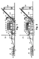
- the production plant shown in the drawings comprises a drying and mixing drum 10, which is so mounted that it may be rotated about its longitudinal axis by means of driving motors 11, which, possibly via a gear, drive a friction roll engaging with friction rings 12 arranged on the outer peripheral surface of the drum.
- the drum 10 is rotatably mounted on a supporting frame 13 having one end connected to a stationary support 15 via a hinge connection 14.
- the other end of the supporting frame 13 may be lifted or lowered by means of one or more hydraulic cylinders 16 or mechanical lifting means, the frame 13 then being rotated about its hinge connection 14, so that the direction or inclination of the longitudinal axis of the drum 10 may be changed.
- a burner 17 is arranged at the inlet end of the drum 10.
- the burner 17 is directed into the drum and is so mounted in relation to the drum that the direction of the burner may be changed in the horizontal as well as in the vertical direction in relation to the drum axis by means of suitable moving means, not shown. Further, the fuel flow fed to the burner and the ratio between the amounts of fuel and combustion air may be adjusted to adjust the heating effect.
- a number of aggregate or raw material silos 18 contains a number of fractions, respectively, of sand and gravel material of well-defined grain sizes.
- certain amounts of material or aggregate may be metered from the individual silos by means of metering devices 19, which may, for example, comprise discharge bands, the speed of which may be controlled, weighing cells, etc.
- metering devices 19 may, for example, comprise discharge bands, the speed of which may be controlled, weighing cells, etc.
- These amounts of material or aggregate fall onto an underlying conveyor belt 20 from which they are passed to a longitudinally extending conveyor 21 extending from the outlet end of the conveyor belt to a further conveyor 23 arranged on a higher level.
- the sand and gravel material the composition of which with regard to grain size and other properties corresponds to the recipe, is now passed into the inlet end of the drying and mixing drum 10 by means of the conveyor 23.
- the drum 10 Between its ends the drum 10 comprises a material intake 24, by means of which one or more further materials or aggregate, for example recycled material in the form of old, broken asphalt pavement, filler, chemical additives, etc., may be introduced at a desired location of the drum. Two or more such material intakes may be provided in the drum, if desired.
- the material(s) supplied to the intake 24 may be metered from a silo 25 and from the latter be passed to the intake 24 by means of a conveyor 26, vide Fig. 3.
- the design of the intake 24 will be described in further detail below with reference to Fig. 7.
- Binders such as bitumen and/or other liquid additives and any solid additives, such as fluxing agents, filler (filter dust, lime, etc.) and other additives which are mixed into the liquid additives, may be introduced into the drum 10 via a supply tube or pipe 58 (vide Fig. 4).
- One end of the pipe 58 is connected to a binder source, for example via a metering pump, not shown, and the other end of the pipe extends through one of the end openings of the drum 10 into and along the drum so that the supply pipe 58 opens into a section of the drum 10 where it is desired to introduce the binders and/or the additives.
- solid additives may be blown into or pushed into the drum 10 through a similar supply pipe.
- filler material may be supplied into the drum 10 from a filler silo 22 through one of the supply tubes 58.
- the supply pipe(s) 58 may be arranged so as to be longitudinally displaceable in relation to the drum so that the position in the drum where the additives are discharged, may be changed, for example depending on whether the drum is used for drum-mixing or batch-mixing.
- the mixed product or the mixed asphalt leaving the outlet end of the drum 10 may optionally be passed either to a conveyor 27 or to a conveyor 29.
- the conveyor 27 which may, for example, be a drag chain conveyor, passes the mixture to a silo 28 for finished product, while the conveyor 29, which may, for example be a bucket conveyor, passes the mixture to a mixing apparatus 30.
- the outlet end of the drum 10 opens into a chamber 31 the top of which is connected to an air suction duct 32 communicating with a filter aggregate 33 which serves to filter off dust and other small solid particles from the air and the combustion gases flowing through the drum 10.
- An air duct 34 connects the filter aggregate 33 to a suction fan 35 which is driven by an electric motor 36, and whose air outlet 37 is connected to a chimney 38.
- an electronic control device such as a microcomputer 39.
- a buffer container or silo 41 which may be provided with weighing cells, may be arranged above the mixing apparatus 30 provided with mixing rotors 40.
- the inlet 42 of a conveyor 43 which may lead to finished product silos, not shown, is arranged immediately below the mixing apparatus 30.
- the conveyor 29, the buffer container 41, the mixing apparatus 30, the conveyor inlet 42 and the outlet end of the drum 10 may be arranged in a closed housing 44 which may possibly replace the chamber 31. In such a case, the housing is connected to the air suction duct 32.
- vanes 45 may be arranged along at least certain drum sections as shown in Fig. 5. These vanes which may, for example, have an angular or J-shaped cross-section as shown, but which may have any other suitable form, serve to a certain extent to carry along some of the material being treated in the drum during the rotation of the drum 10. As indicated in Fig. 5, the material carried by the vanes 45 will fall down from the vanes when they have been moved to an upper position, and the falling material will thus cover a smaller or larger part of the inner drum cross-section.
- the vanes 45 may extend along a helical or rectilinear path, and the vanes may possibly be longitudinally offset in relation to each other.
- the burner is preferably adjusted during the operation of the plant in such a manner that it is constantly directed approximately towards the centre 46 of the part of the drum cross-section which is covered by the falling material.
- annular partition wall 47 like the one shown in Fig. 6 may be arranged on the inner wall of the drum between adjacent drum sections. This partition wall is divided into a plurality of ring sectors 48, and each of these ring sectors is rotatable about a radially directed shaft or pivot pin 49.
- These shafts projecting from the outer side surface of the drum may be interconnected, for example by means of gears, chains or other connecting means, so that they may all be moved by rotating one of the shafts from a rotational position shown in Fig. 6 in which the partition wall 47 is closed and all of the ring sectors 48 extend at substantially right angles to the drum axis, and into another rotational position in which the partition wall is open and all of the ring sectors extend substantially parallel to the drum axis or form an acute angle therewith.
- the ring sectors 48 may then be moved from their closed position to their open position when a material portion is to be transferred from one drum section to another as will be explained in detail below.
- Fig. 6 the partition wall 47 is closed and all of the ring sectors 48 extend at substantially right angles to the drum axis, and into another rotational position in which the partition wall is open and all of the ring sectors extend substantially parallel to the drum axis or form an acute angle therewith.
- the ring sectors 48 may then be moved from their closed position to their open position when
- an end wall 50 may be arranged at the outlet end of the drum 10, which end wall is preferably annular and which may be moved by means of a hydraulic cylinder 51 or similar moving means between a closed position in which the end wall is adjacent to the outlet end of the drum 10, and an open position in which the outlet end of the drum is open.
- the material intake 24 indicated in Figs. 1-4 is a stationary annular material introduction chamber 52 into which material is introduced from the silo 25 by means of the conveyor 26. This material may fall into the drum 10 from the chamber 52 through an annular row of mutually spaced openings 53 which are formed in the drum wall.
- An obliquely extending baffle plate or bucket 54 projecting into the inner space of the drum is aligned with each of the openings 53 and is shaped so as to move the material in a direction indicated by an arrow 55 towards the outlet end of the drum 10.
- drum-mixing principle means that sand and stone materials from the silos 18 are continuously supplied to the inlet end of the drum 10 in the ratios corresponding to those in the asphalt recipe.
- the drum 10 is rotated at a suitable rotational speed by means of the driving motors 11, and the direction of the burner 17 is adjusted in such a manner that an optimum heating effect is obtained at the resulting material flow rate. Further, the air and fuel supply to the burner is controlled in such a manner in relation to the material flow that the stone and sand material flowing through the drum 19 is heated and dried to the desired extent.
- Bitumen, filler, recycled material in the form of used, broken asphalt pavement, additives, etc. are continuously passed into the drum through the material intake 24 and the supply tube or tubes 58 and through any other corresponding material inlets.
- the finished hot asphalt mixture leaves the drum 10 continuously through its outlet end and is passed to the finished product silo 28 via the drag chain conveyor 27.
- any internal partition walls 47 in the drum may be constantly in their open position, and the end wall 50 of the drum may be constantly in its open position so that the materials passed into the drum 10 may fairly freely move along through the drum, and the finished asphalt mixture may likewise flow out freely from the outlet end of the drum.
- the production plant is to be used for the production of small amounts of asphalt mixture (for example 2000-4000 kg) according to the same recipe, the plant is advantageously operated according to the batch-mixing principle.
- Metered amounts of sand and stone material in the ratio prescribed by the recipe is metered from the silos 18 and then passed into the drum 10 by means of the conveyors 21 and 23. This material portion is introduced into the first drum section, which is adjacent to the inlet end of the drum 10.
- the drum 10 is now rotated at a suitable rotational speed, and the direction of the burner 17 is adjusted in dependency of the pattern formed by the falling material across the drum cross-section (vide Fig. 5) so that an optimum exploitation of the heat energy developed by the burner is obtained.
- the drum 10 is preferably given a constant small inclination downward in the direction of the outlet end during the whole process.
- the hydraulic cylinders 16 are preferably adjusted so that the drum axis is substantially horizontal. This causes all the amount of material being treated in the first drum section to remain therein.
- the drum sections may be separated by means of an annular partition wall 47 as the one shown in Fig. 6. During operation of the drum this partition wall will be in its closed position, and the end wall 50 of the drum will also be closed.
- the inlet end of the drum 10 is lifted by means of the cylinders 16 so that the drum will incline towards the outlet end.
- the annular partition wall 47 is opened. This causes the heated and dried material portion to slide from the first drum section into the second drum section.
- the partition wall 47 is now closed again, and a new portion of sand and stone material of a new composition may be introduced into the first drum section from the silos 18.
- the hydraulic cylinders 16 may now be operated so as to bring the drum 10 back into its substantially horizontal position.
- metered material portions to be mixed with the dry and heated sand and stone material in the second drum section may be passed into this second drum section from the silo 25 by means of the conveyor 26, via the material intake 24 and/or through the supply tube 58.
- These further materials may be one or more of the following materials: Binders, such as bitumen, recycled materials in the form of broken, used asphalt pavement, filler, additives, etc.
- the inlet end of the drum is again lifted by means of the cylinders 16, and the end wall 50 of the drum 10 is opened so that the finished mixed material portion may be either poured into the supply end of the conveyor 27 and be passed into the product silo 28 or - if the mixture is to have further substances added to it - poured into the supply end of the conveyor 29 and be passed into the buffer silo 41.
- the mixture is passed into the mixing apparatus 30 in metered amounts together with metered amounts of the further desired additives, such as colouring agents, certain chemicals, etc.
- the end wall 50 of the drum is again closed, and the annular partition wall 47, if any, is opened so that the heated and dried material portion from the first drum section may slide into the second drum section.
- a new portion of raw materials may be passed into the first drum section from the silos 18, whereupon the inlet end of the drum may again be lowered, and the process described above may be repeated.
- measuring probes may be arranged at different locations in the mixing apparatus, which probes measure the percentage content of one of the material components added.
- the mixing process may be interrupted, and the mixed material may be emptied into the inlet 42 of the conveyor 43 which may pass the finished portion of asphalt mixture into a product silo for finished product, not shown.
- the drum 10 may be divided into more than two drum sections so that more than two material portions of different compositions may be treated simultaneously in the drum. Different material components may then be added and mixed in for example the second and the third drum sections.
- the plant may be operated in such a manner in batch-mixing that only one material portion is present in the drum 10 at a time, this material portion, after heating and drying in the first drum section, being poured directly into the inlet end of the conveyor 29 and passed from there via the buffer silo 41 to the mixing apparatus 30. Both bitumen and filler and any additives may then be mixed together with the heated and dried sand and stone materials in the mixing apparatus 30.
- the electronic control device or microcomputer 39 indicated in Fig. 3 may control and monitor the operation of the whole plant.
- a very large number of recipes for different types of paving or asphalt mixtures may be stored in the memory of the microcomputer.
- the microcomputer may control the metering of sand and stone material from the silos 18 which is passed to the inlet end of the drum 10, the metering of bitumen, filler, pigment, latex and/or other additives via the intake 24 and/or the supply tube 58.
- the computer may also control the timing of releasing and supplying the various materials to be mixed so that they arrive at their final destination, i.e. the final mixing zone in the system at substantially the same time.
- the computer may control one or more of the following operations: The addition of further additives to the mixing apparatus 30, rotation and tilting of the drum 10, the function of the filter 33, recycling of material filtered off to the drum 10 or the mixing apparatus 30, adjustment of the burner 17, adjustment of supply of air and fuel to the burner 17, supply of surplus combustion air to the burner 17 based on measurement of CO or O2 present in the combustion gas, the temperature of combustion gas within the drum 10, opening and closing operations of the partition wall 47 and the end closure or end wall 50.
- the computer 39 may further be adjusted to monitor a correct function of the various units and to give the alarm in the case of a malfunction.
- the control device or the microcomputer 39 may further control the location of the supply tube(s) 58 and the time for the supply of metered amounts of bitumen, filler, flux agents and other additives in the case of batch-mixing.
- This control of the location and time may, for example, be made by means of equipment comprising one or more of the following devices:
Landscapes
- Engineering & Computer Science (AREA)
- Architecture (AREA)
- Civil Engineering (AREA)
- Structural Engineering (AREA)
- Road Paving Machines (AREA)
- Compositions Of Macromolecular Compounds (AREA)
- Working-Up Tar And Pitch (AREA)
Claims (10)
- Verfahren zur Herstellung eines bitumisösen Straßendekkengemisches, wobei man bei dem Verfahren Zuschlagstoffe, beispielsweise Sand und/oder Kies, in einen ersten Bereich einer sich drehenden Trocken- und Mischtrommel (10) an einem Einlaßende davon einführt, mindestens eine weitere Komponente, z.B. ein Bindemittel wie Bitumen und/oder Recyclinmaterial, in einen zweiten Bereich der Trommel zwischen dem Einlaßende und einem entgegengesetzten Auslaßende der Trommel einführt, die Komponente mit den getrockneten Zuschlagstoffen in der Trommel mischt und das Gemisch aus dem anderen Ende der Trommel austrägt,
gekennzeichnet durch die Schritte, daß man
die Zuschlagstoffe der Trommel in Portionen zuführt, jede Portion in dem ersten Bereich der Trommel trocknet, eine erste Portion in den zweiten Bereich der Trommel nach dem Trocknen dieser Portion und vor dem Zuführen einer zweiten Portion Zuschlagstoffe in die Trommel überführt und die getrocknete erste Portion Zuschlagstoffe mit weiteren Komponenten in dem zweiten Bereich der Trommel mischt, wobei die erste und zweite Portion in der Trommel im wesentlichen auseinandergehalten werden. - Verfahren nach Anspruch 1, gekennzeichnet durch den weiteren Schritt, daß man gleichzeitig mehrere getrennte Portionen Zuschlagstoffe in unterschiedlichen Bereichen der Trommel behandelt.
- Verfahren nach Anspruch 1 oder 2, gekennzeichnet durch den Schritt, daß man Portionen Zuschlagstoffe aus einem Bereich der Trommel in einen nachfolgenden Bereich überführt und soweit möglich auch das Gemisch aus der Trommel (10) austrägt, indem man die Trommel neigt und/oder die Umdrehungsgeschwindigkeit der Trommel erhöht.
- Trocknungs- und Mischanlage für die Herstellung eines bituminösen Straßendeckengemisches, wobei die Anlage eine Trocknungs- und Mischtrommel (10) mit Einlaß- und Auslaßenden aufweist, eine Antriebseinrichtung (11, 12) zum Drehen der Trommel um ihre Längsachse, eine Einrichtung (21-23) zum Einspeisen von Zuschlagstoffen in die Trommel an ihrem Einlaßende, eine Einrichtung (24-26) zum Zuführen einer weiteren Komponente, wie beispielsweise eines Bindemittels, in die Trommel an Orten zwischen dem Einlaß- und Auslaßende und eine Einrichtung (16) zur Neigungseinstellung zum Anheben und Absenken der Trommel (10), um die Neigung der Trommelachse zu verändern,
dadurch gekennzeichnet,
daß eine Verschlußeinrichtung (50, Fig. 4) vorgesehen ist, um selektiv das Auslaßende der Trommel (10) mindestens teilweise zu öffnen und zu schließen und daß die Trommel (10) mit mindestens einer ringförmigen Trennwand (47, Fig. 6), die sich radial von der inneren Wand der Trommel nach innen erstreckt, in Bereiche unterteilt ist, wobei die Trennwand selektiv zwischen einer Lage bewegbar ist, in der der Materialfluß zwischen benachbarten Bereichen der Trommel versperrt ist und einer Lage, in der das Material frei von einem Bereich zu einem anderen fließen kann. - Anlage nach Anspruch 4, mit einer Heizeinrichtung, die mindestens einen in die Trommel gerichteten Brenner (17) aufweist, dadurch gekennzeichnet, daß der Brenner (17) so montiert ist, daß seine Richtung verändert werden kann.
- Anlage nach Anspruch 4 oder 5, dadurch gekennzeichnet, daß die ringförmige Trennwand (47) in Ringsektoren (48) unterteilt ist, von denen mindestens einige beweglich sind zwischen einer versperrenden Lage, in der sie sich quer zur Trommelachse erstrecken und einer nicht versperrenden Lage, in der sie sich im wesentlichen parallel dazu erstrecken oder einen spitzen Winkel damit definieren.
- Anlage nach einem der Ansprüche 4 bis 6, dadurch gekennzeichnet, daß die Einrichtung zum Zuführen einer weiteren Komponente eine sich am Umfang erstreckende Ablenkwand (54) aufweist, die von der Innenwand der Trommel (10) radial nach innen vorspringt und eine Einlaß-Kammeröffnung zu den Auslaßenden der Trommel hin definiert, wobei die Ablenkwand in Sektoren unterteilt ist, um umfangsmäßige Zwischenräume (56) zwischen benachbarten Sektoren zu definieren.
- Anlage nach einem der Ansprüche 4 bis 7, dadurch gekennzeichnet, daß sie weiter eine Mischvorrichtung (30) aufweist, die mit dem Auslaßende der Trommel mit Hilfe eines Förderers (29) in Verbindung steht.
- Anlage nach einem der Ansprüche 4 bis 8, dadurch gekennzeichnet, daß sie eine elektronische Steuereinrichtung (39) aufweist zum Steuern von einer oder mehreren der folgenden Bedingungen: der Neigung der Trommelachse, der Umdrehungsgeschwindigkeit der Trommel (10), der Drehrichtung der Trommel, der Lage der Verschlußeinrichtung (50), der Lage der Trennwand (47), der Einstellung des Brenners (17), der Richtung des Brenners und der Zusammensetzung und der Temperatur des hergestellten Straßendeckengemisches.
- Verfahren nach einem der Ansprüche 4 bis 9, dadurch gekennzeichnet, daß am Auslaßende der Trommel (10) eine Endwand (50, Fig. 4) oder ein Verschluß angeordnet ist, die (der) in Relation zur Trommel zwischen einer geschlossenen Lage bewegt werden kann, in der das Auslaßende der Trommel ganz oder teilweise geschlossen ist und einer offenen Lage, in der das Auslaßende offen ist.
Priority Applications (2)
| Application Number | Priority Date | Filing Date | Title |
|---|---|---|---|
| AT89113397T ATE85819T1 (de) | 1988-07-27 | 1989-07-21 | Methode und anlage zur herstellung von bituminoesem mischgut fuer decken. |
| DK550289A DK550289A (da) | 1989-07-21 | 1989-11-03 | Fremgangsmaade og anlaeg til fremstilling af en bituminoes vejbelaegningsblanding |
Applications Claiming Priority (2)
| Application Number | Priority Date | Filing Date | Title |
|---|---|---|---|
| DK420888A DK420888D0 (da) | 1988-07-27 | 1988-07-27 | Fremgangsmaade og anlaeg til fremstilling af asfalt og lignende produkter |
| DK4208/88 | 1988-07-27 |
Publications (2)
| Publication Number | Publication Date |
|---|---|
| EP0352648A1 EP0352648A1 (de) | 1990-01-31 |
| EP0352648B1 true EP0352648B1 (de) | 1993-02-17 |
Family
ID=8131318
Family Applications (1)
| Application Number | Title | Priority Date | Filing Date |
|---|---|---|---|
| EP89113397A Expired - Lifetime EP0352648B1 (de) | 1988-07-27 | 1989-07-21 | Methode und Anlage zur Herstellung von bituminösem Mischgut für Decken |
Country Status (8)
| Country | Link |
|---|---|
| US (1) | US5190371A (de) |
| EP (1) | EP0352648B1 (de) |
| AT (1) | ATE85819T1 (de) |
| AU (1) | AU4048889A (de) |
| DE (1) | DE68904933T2 (de) |
| DK (1) | DK420888D0 (de) |
| ES (1) | ES2038380T3 (de) |
| WO (1) | WO1990001086A1 (de) |
Cited By (1)
| Publication number | Priority date | Publication date | Assignee | Title |
|---|---|---|---|---|
| US8075681B2 (en) | 2007-12-21 | 2011-12-13 | Eurovia | Process for producing two-phase mixes |
Families Citing this family (15)
| Publication number | Priority date | Publication date | Assignee | Title |
|---|---|---|---|---|
| FR2658213B1 (fr) * | 1990-02-12 | 1993-05-21 | Ermont Cm | Procede et dispositif de fabrication de produits enrobes bitumineux en continu ou en discontinu, a partir d'agregats et de bitume. |
| DE4110981A1 (de) * | 1991-04-05 | 1992-10-08 | Wibau Gmbh | Verfahren zur herstellung von asphaltgemischen mit einer ueber den mischturm angeordneten trocken- und heiztrommel sowie ergaenzung des verfahrens fuer die teilaufgabe der abgaskuehlung und -waesche |
| US5556197A (en) * | 1994-11-04 | 1996-09-17 | Gentec Equipment Company | Asphalt plant for both continuous and batch operation |
| US6027338A (en) * | 1996-11-07 | 2000-02-22 | Matsushita Electric Industrial Co., Ltd. | Furnace and method for firing ceramics |
| FI20000925L (fi) * | 2000-04-18 | 2001-10-19 | Kalevi Juhani Hakkarainen | Päällystemassa-asema |
| US20040132842A1 (en) * | 2002-10-16 | 2004-07-08 | Darrin Coffey | System and method for recycling scrap fiberglass products in concrete and asphalt construction |
| FR2953866A1 (fr) * | 2009-12-14 | 2011-06-17 | Famaro | Installation de preparation d'un produit enrobe bitumineux a partir de granulats et de bitume. |
| FR2960891A1 (fr) * | 2010-06-02 | 2011-12-09 | Famaro | Procede d'homogeneisation du melange des materiaux au debut d'un cycle de production de produits enrobes bitumineux. |
| MX2011001458A (es) * | 2011-02-08 | 2012-08-30 | Rodolfo Villalobos Davila | Equipo industrial para reciclado de mezclas asfalticas en caliente. |
| FR2983495B1 (fr) * | 2011-12-01 | 2014-01-03 | Famaro | Procede d'homogeneisation du melange des materiaux au debut d'un regime de production de produits enrobes bitumineux |
| FR2989393B1 (fr) | 2012-04-13 | 2014-06-06 | Argumat | Dispositif de fabrication de produits enrobes a chaud a sortie derivee et malaxeur externe et procede de fabrication d'enrobes a chaud correspondants |
| ITVI20130180A1 (it) * | 2013-07-16 | 2015-01-17 | Ri Co Nove S R L | Metodo per la miscelazione e il trasferimento di impasti bituminosi da una stazione di carico ad una stazione di scarico e attrezzatura per la miscelazione e il trasferimento di impasti bituminosi che realizza tale metodo |
| CN107974899B (zh) * | 2017-12-08 | 2019-04-12 | 段莉娟 | 一种交通道路路面整修沥青混凝土路基摊铺自动化机械 |
| GB2606682B (en) * | 2020-10-02 | 2024-10-30 | Vol Tar Ltd | Volumetric mixer |
| CN113416570A (zh) * | 2021-06-28 | 2021-09-21 | 河北交科材料科技有限公司 | 高效环保改性沥青发育罐 |
Family Cites Families (14)
| Publication number | Priority date | Publication date | Assignee | Title |
|---|---|---|---|---|
| US29496A (en) * | 1860-08-07 | kubler | ||
| US3026627A (en) * | 1960-01-04 | 1962-03-27 | R N Corp | Rotary cylindrical heat transfer device |
| NL6701529A (de) * | 1964-10-09 | 1968-08-02 | ||
| AT324397B (de) * | 1971-01-19 | 1975-08-25 | Wibau Gmbh | Kombinierte misch-, trocknungs- und erhitzungseinrichtung zur kontinuierlichen oder diskontinuierlichen aufbereitung bituminösen mischgutes |
| US3866888A (en) * | 1973-01-26 | 1975-02-18 | Baldwin Thomas I | Apparatus for making hot asphalt paving material |
| US4095284A (en) * | 1975-08-11 | 1978-06-13 | Mendenhall Robert Lamar | Direct heating asphalt-aggregate recycle apparatus and method |
| US4089508A (en) * | 1976-02-18 | 1978-05-16 | Alliance Industries, Inc. | Method of processing bituminous paving mixtures and apparatus therefor |
| US4326809A (en) * | 1978-01-23 | 1982-04-27 | Mendenhall Robert Lamar | Recycling apparatus for asphaltic concrete |
| US4208131A (en) * | 1978-01-23 | 1980-06-17 | Mendenhall Robert Lamar | Asphaltic concrete patch mixing and heating apparatus and method |
| FR2441682A1 (fr) * | 1978-11-17 | 1980-06-13 | Creusot Loire | Dispositif pour la preparation de produits enrobes bitumineux pour revetements routiers |
| US4190370A (en) * | 1978-11-24 | 1980-02-26 | Astec Industries, Inc. | Asphalt plant with improved temperature control system |
| FR2473578B1 (de) * | 1980-01-11 | 1986-03-21 | Creusot Loire | |
| US4715720A (en) * | 1984-11-05 | 1987-12-29 | Astec Industries, Inc. | Drum mix asphalt plant with knock-out box and separate pugmill coater |
| US4813784A (en) * | 1987-08-25 | 1989-03-21 | Musil Joseph E | Reverse flow post-mixer attachment and method for direct-fired asphaltic concrete drum mixers |
-
1988
- 1988-07-27 DK DK420888A patent/DK420888D0/da not_active Application Discontinuation
-
1989
- 1989-07-21 DE DE8989113397T patent/DE68904933T2/de not_active Expired - Fee Related
- 1989-07-21 ES ES198989113397T patent/ES2038380T3/es not_active Expired - Lifetime
- 1989-07-21 EP EP89113397A patent/EP0352648B1/de not_active Expired - Lifetime
- 1989-07-21 AT AT89113397T patent/ATE85819T1/de not_active IP Right Cessation
- 1989-07-26 AU AU40488/89A patent/AU4048889A/en not_active Abandoned
- 1989-07-26 US US07/640,307 patent/US5190371A/en not_active Expired - Fee Related
- 1989-07-26 WO PCT/DK1989/000183 patent/WO1990001086A1/en not_active Ceased
Cited By (1)
| Publication number | Priority date | Publication date | Assignee | Title |
|---|---|---|---|---|
| US8075681B2 (en) | 2007-12-21 | 2011-12-13 | Eurovia | Process for producing two-phase mixes |
Also Published As
| Publication number | Publication date |
|---|---|
| ES2038380T3 (es) | 1993-07-16 |
| WO1990001086A1 (en) | 1990-02-08 |
| DE68904933D1 (de) | 1993-03-25 |
| US5190371A (en) | 1993-03-02 |
| ATE85819T1 (de) | 1993-03-15 |
| AU4048889A (en) | 1990-02-19 |
| EP0352648A1 (de) | 1990-01-31 |
| DK420888D0 (da) | 1988-07-27 |
| DE68904933T2 (de) | 1993-06-03 |
Similar Documents
| Publication | Publication Date | Title |
|---|---|---|
| EP0352648B1 (de) | Methode und Anlage zur Herstellung von bituminösem Mischgut für Decken | |
| US4802139A (en) | Apparatus for producing a heated reproduction asphalt mixture | |
| EP0181858A1 (de) | Wiederverwendungsanlage für asphalt | |
| CN102345265A (zh) | 隔档进料式热拌间歇式沥青混合料拌和机及其生产工艺 | |
| EP2657404A2 (de) | Vorrichtung und Verfahren zum Trocknen von Partikelmaterial | |
| GB2485229A (en) | Apparatus for drying particulate materials | |
| US2344228A (en) | Mixing plant | |
| GB2458975A (en) | Handling aggregate in an asphalt plant | |
| CN109423944A (zh) | 一种改性沥青生产线 | |
| US4921730A (en) | Method of producing a recycled asphalt mixture | |
| US5607231A (en) | Method for operating an asphalt plant for both continuous and batch operation | |
| US3514870A (en) | Drying apparatus | |
| JP2002129515A (ja) | アスファルトプラント | |
| US20210381175A1 (en) | Hi-recycle asphalt batch plant | |
| IES960064A2 (en) | "Manufacture of bituminous materials" | |
| JP3366600B2 (ja) | アスファルト合材の製造装置 | |
| JPS63138005A (ja) | アスフアルトプラント | |
| CN117947674B (zh) | C式强制间歇沥青混合料原生再生一体机 | |
| JPH0250241B2 (de) | ||
| Kennedy et al. | Drum mix plants: Equipment and operations | |
| CN217748030U (zh) | 一种新型沥青一体机 | |
| JP3955751B2 (ja) | アスファルト混合物の製造方法 | |
| US1206918A (en) | Machine for making asphaltic or other mixtures. | |
| JP2582905Y2 (ja) | 熱交換装置 | |
| TR2022014339A1 (tr) | Kule ti̇pi̇ bi̇r mobi̇l asfalt plenti̇ |
Legal Events
| Date | Code | Title | Description |
|---|---|---|---|
| PUAI | Public reference made under article 153(3) epc to a published international application that has entered the european phase |
Free format text: ORIGINAL CODE: 0009012 |
|
| AK | Designated contracting states |
Kind code of ref document: A1 Designated state(s): AT BE CH DE ES FR GB GR IT LI LU NL SE |
|
| 17P | Request for examination filed |
Effective date: 19900713 |
|
| 17Q | First examination report despatched |
Effective date: 19911107 |
|
| RAP1 | Party data changed (applicant data changed or rights of an application transferred) |
Owner name: PEDERSHAAB A/S |
|
| GRAA | (expected) grant |
Free format text: ORIGINAL CODE: 0009210 |
|
| AK | Designated contracting states |
Kind code of ref document: B1 Designated state(s): AT BE CH DE ES FR GB GR IT LI LU NL SE |
|
| PG25 | Lapsed in a contracting state [announced via postgrant information from national office to epo] |
Ref country code: NL Effective date: 19930217 Ref country code: GR Free format text: LAPSE BECAUSE OF FAILURE TO SUBMIT A TRANSLATION OF THE DESCRIPTION OR TO PAY THE FEE WITHIN THE PRESCRIBED TIME-LIMIT Effective date: 19930217 Ref country code: BE Effective date: 19930217 Ref country code: AT Effective date: 19930217 |
|
| REF | Corresponds to: |
Ref document number: 85819 Country of ref document: AT Date of ref document: 19930315 Kind code of ref document: T |
|
| ITF | It: translation for a ep patent filed | ||
| ET | Fr: translation filed | ||
| REF | Corresponds to: |
Ref document number: 68904933 Country of ref document: DE Date of ref document: 19930325 |
|
| NLV1 | Nl: lapsed or annulled due to failure to fulfill the requirements of art. 29p and 29m of the patents act | ||
| REG | Reference to a national code |
Ref country code: ES Ref legal event code: FG2A Ref document number: 2038380 Country of ref document: ES Kind code of ref document: T3 |
|
| PG25 | Lapsed in a contracting state [announced via postgrant information from national office to epo] |
Ref country code: LU Free format text: LAPSE BECAUSE OF NON-PAYMENT OF DUE FEES Effective date: 19930731 |
|
| PLBE | No opposition filed within time limit |
Free format text: ORIGINAL CODE: 0009261 |
|
| STAA | Information on the status of an ep patent application or granted ep patent |
Free format text: STATUS: NO OPPOSITION FILED WITHIN TIME LIMIT |
|
| 26N | No opposition filed | ||
| EAL | Se: european patent in force in sweden |
Ref document number: 89113397.7 |
|
| PGFP | Annual fee paid to national office [announced via postgrant information from national office to epo] |
Ref country code: GB Payment date: 19960702 Year of fee payment: 8 |
|
| PGFP | Annual fee paid to national office [announced via postgrant information from national office to epo] |
Ref country code: DE Payment date: 19960709 Year of fee payment: 8 |
|
| PGFP | Annual fee paid to national office [announced via postgrant information from national office to epo] |
Ref country code: SE Payment date: 19960716 Year of fee payment: 8 |
|
| PGFP | Annual fee paid to national office [announced via postgrant information from national office to epo] |
Ref country code: ES Payment date: 19960724 Year of fee payment: 8 |
|
| PGFP | Annual fee paid to national office [announced via postgrant information from national office to epo] |
Ref country code: FR Payment date: 19960729 Year of fee payment: 8 Ref country code: CH Payment date: 19960729 Year of fee payment: 8 |
|
| PG25 | Lapsed in a contracting state [announced via postgrant information from national office to epo] |
Ref country code: GB Free format text: LAPSE BECAUSE OF NON-PAYMENT OF DUE FEES Effective date: 19970721 |
|
| PG25 | Lapsed in a contracting state [announced via postgrant information from national office to epo] |
Ref country code: SE Effective date: 19970722 Ref country code: ES Free format text: LAPSE BECAUSE OF THE APPLICANT RENOUNCES Effective date: 19970722 |
|
| PG25 | Lapsed in a contracting state [announced via postgrant information from national office to epo] |
Ref country code: LI Free format text: LAPSE BECAUSE OF NON-PAYMENT OF DUE FEES Effective date: 19970731 Ref country code: CH Free format text: LAPSE BECAUSE OF NON-PAYMENT OF DUE FEES Effective date: 19970731 |
|
| GBPC | Gb: european patent ceased through non-payment of renewal fee |
Effective date: 19970721 |
|
| REG | Reference to a national code |
Ref country code: CH Ref legal event code: PL |
|
| PG25 | Lapsed in a contracting state [announced via postgrant information from national office to epo] |
Ref country code: FR Free format text: LAPSE BECAUSE OF NON-PAYMENT OF DUE FEES Effective date: 19980331 |
|
| PG25 | Lapsed in a contracting state [announced via postgrant information from national office to epo] |
Ref country code: DE Free format text: LAPSE BECAUSE OF NON-PAYMENT OF DUE FEES Effective date: 19980401 |
|
| EUG | Se: european patent has lapsed |
Ref document number: 89113397.7 |
|
| REG | Reference to a national code |
Ref country code: FR Ref legal event code: ST |
|
| REG | Reference to a national code |
Ref country code: ES Ref legal event code: FD2A Effective date: 20001102 |
|
| PG25 | Lapsed in a contracting state [announced via postgrant information from national office to epo] |
Ref country code: IT Free format text: LAPSE BECAUSE OF NON-PAYMENT OF DUE FEES;WARNING: LAPSES OF ITALIAN PATENTS WITH EFFECTIVE DATE BEFORE 2007 MAY HAVE OCCURRED AT ANY TIME BEFORE 2007. THE CORRECT EFFECTIVE DATE MAY BE DIFFERENT FROM THE ONE RECORDED. Effective date: 20050721 |