EP0352663A2 - Procédé de fabrication d'une fourche de bicyclette et fourche de bicyclette fabriquée par un tel procédé - Google Patents
Procédé de fabrication d'une fourche de bicyclette et fourche de bicyclette fabriquée par un tel procédé Download PDFInfo
- Publication number
- EP0352663A2 EP0352663A2 EP89113468A EP89113468A EP0352663A2 EP 0352663 A2 EP0352663 A2 EP 0352663A2 EP 89113468 A EP89113468 A EP 89113468A EP 89113468 A EP89113468 A EP 89113468A EP 0352663 A2 EP0352663 A2 EP 0352663A2
- Authority
- EP
- European Patent Office
- Prior art keywords
- fork
- plastic
- steering pin
- pin
- fiber
- Prior art date
- Legal status (The legal status is an assumption and is not a legal conclusion. Google has not performed a legal analysis and makes no representation as to the accuracy of the status listed.)
- Granted
Links
Images


Classifications
-
- B—PERFORMING OPERATIONS; TRANSPORTING
- B62—LAND VEHICLES FOR TRAVELLING OTHERWISE THAN ON RAILS
- B62K—CYCLES; CYCLE FRAMES; CYCLE STEERING DEVICES; RIDER-OPERATED TERMINAL CONTROLS SPECIALLY ADAPTED FOR CYCLES; CYCLE AXLE SUSPENSIONS; CYCLE SIDECARS, FORECARS, OR THE LIKE
- B62K19/00—Cycle frames
- B62K19/02—Cycle frames characterised by material or cross-section of frame members
- B62K19/16—Cycle frames characterised by material or cross-section of frame members the material being wholly or mainly of plastics
Definitions
- the invention relates to a method for producing a bicycle fork according to the preamble of patent claim 1 and a bicycle fork according to the preamble of patent claim 8.
- the aim of the present invention is therefore to provide a method of the type mentioned and a bicycle fork manufactured thereafter, in which or in which the metal or fiber-reinforced plastic parts can be connected to one another in a simple and uncomplicated manner, without the later Use of a solution of the interconnected parts must be feared.
- the invention thus seeks to create a bicycle fork made of metal and fiber-reinforced plastic parts which, although made from very different materials, has practically the properties, ie in particular the strength and the durability but not the weight of a conventional one-piece metal fork.
- the features of the characterizing part of claim 1 are provided.
- the idea of the invention is therefore to be seen in the fact that the plastic impregnation of the sleeves forming the fork arms and the fork head is only liquefied and hardened after the connection to the tubular metal steering pin or the metal connecting pin of the axle holder has been established. Since the final curing takes place under pressure in a mold and preferably also by means of a plunger according to claim 5, a conceivably intimate connection between metal and plastic parts is realized.
- the result is an overall composite bicycle fork that is even superior in strength and durability to a one-piece bicycle fork made of metal, but nevertheless has a significantly reduced weight.
- An important feature of the present invention is the elongated shaping core used in the manufacture, which on the one hand must be sufficiently flexible to be able to be easily adapted to the shape of the fork arms and the clevis within the mold, but is nevertheless so rigid against external pressure that the individual casings placed around the core can be applied without problems and can assume and retain the shape given by the outer shape of the core until hardening.
- a particularly intimate connection between the steering pin and the fork head is achieved by the measures of claims 6 and 7 because the lower end region of the steering pin is thereby molded into the plastic of the fork head with both its inside and its outside.
- the invention thus creates an arrangement that behaves practically like a one-piece bicycle fork according to claim 10. While the ribs for a perfect transmission of weight and impact forces, the non-circular cross-section of the connecting pins serves to effectively prevent twisting of the axle holder relative to the fork arms around the fork arm axis.
- a radially outward widening step is provided between the connecting pins and the parts of the axle holder projecting below from the fork arms, which also serves to provide good support for the axle holder on the fork arms.
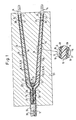
- the bicycle fork according to the invention has a tubular steering pin 11 with a circular cross-section to be inserted later into the steering bearing of a bicycle frame (not shown), in the lower region of which the steering pin connection part 12a of a fork head 12 having a shape complementary to the inner diameter of the steering pin 11 is inserted in a rotationally fixed manner.
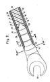
- the steering pin connection part 12a two fork arm transition parts 12b, which merge into the two fork arms 13, in the lower end of which, as shown in FIG. 5, an oval cross-section connecting pins 21 of axle holders 14 engage, in their wheel axle receiving slots 31 (FIG. 2) later the axle ends, not shown, of the axle of a wheel are used.
- the fork arms 13 and the fork head 12 are constructed as follows:
- the hard foam core 19 which has approximately the same diameter as the connecting pins 21 and is adjacent to the connecting pins 21, is provided as the first component of a shaping core, which directly adjoins the connecting pin 21 with a recess 32 complementary to the rounded tip 30 of the connecting pin 31 and then extends to the upper end of the practically rectilinear part of the fork, where the fork arms 13 begin to merge into the fork head 12.
- a substantially the same cross section has a flexible foam core 22 which extends over two opposite curvatures into the lower end of the steering pin 11 (FIGS. 1, 6).
- a first foam shell 20 consists of so-called syntactic foam. This is a resin mixed with glass balls, which is initially flexible, so that it can be brought into any desired curved shape, but still hardens to a rigid plastic body when heated.
- the flexible foam core 22 is also made of the same material.
- the flexible foam shell 20 around a first prepreg sheath is disposed with a fiber or filament mesh or woven fabric, wherein the angle of the pack of filaments or fibers may conveniently be between 30 and o 90th
- the bisector should run in the direction of the axis of the fork head 12 or the fork arms 13.
- the radially outwardly adjoining sheath 16 (FIGS. 1, 2 and 6) preferably consists of threads or fibers which run parallel to the axis and to one another and are therefore laid around the sheath 15 in a ring arrangement.
- a can also be used for the casing 16 Fabrics with threads or fibers arranged at 90 ° to one another are used, but the threads or fibers should run parallel or at right angles to the axis of the fork head 12 and the fork arms 13.
- a further plastic-impregnated sleeve 17 is provided even further radially outward, which again consists of a braid or fabric of the same design and arrangement as the sleeve 15.
- an additional closure sleeve 18 can optionally be provided on the very outside around the arrangement described above, which has either threads or fibers running parallel to one another and to the axis or a fabric which is also impregnated with plastic. All covers are made of syntactic foam.
- a flexible foam gusset 24 which consists of the same syntactic foam as the foam casing 20 and the flexible foam core 22, is still used in the gusset where the two fork arms 13 merge into the fork head 12.
- a plastic-impregnated, saddle-shaped gusset cover 25 is used as reinforcement, which expediently consists of a braid or fabric of fibers or threads impregnated with syntactic foam.
- the ends of the gusset sleeve 25 are molded onto the outer sleeve 17 or 18 fork arms 13 or the fork head 12.
- the steering pin 11 has in its lower region radially outside a circumferential recess 28 into which the outer shell 18 of the fork head 12 is inserted.
- the remaining parts of the steering pin connecting parts 12a are accommodated within the lower end region of the steering pin 11.
- the steering pin 11 still has a concentric ring of continuous anchoring holes 27 in the area of the steering pin connecting part 12a, into which at least the outermost envelope 17 located inside the steering pin 11 extends with the plastic impregnation.
- the axle holder 14 at the transition from the part protruding from the fork arms 13 to the connecting pin 21 has a conically tapering circumferential step 33 to which the connecting pin 21 is connected.
- the connecting pin 21 is provided with annular circumferential ribs 29, which are finally followed by the rounded tip 30.
- the connecting pin 21 and the axle holder 14 have an oval cross section in the region of the peripheral step 33, which is practically realized by two semicircles and short straight connecting pieces.
- the plastic impregnation of the cores 19, 22 and the shells 15, 16, 17, 18 and 20 preferably consists of a plastic which is flexible and unhardened for processing, initially becomes liquid when heated, only to solidify afterwards.
- the bicycle fork described is produced as follows:
- the two elongate structures are then combined to form the steering-pin connection part 12a and, after the outer casing 18 to be inserted into the recess 28, has been cut to size, it is inserted from below into the hollow steering pin 11 up to a point clearly above the anchoring holes 27.
- the outer sleeves 18 come to lie on one another on the axis of the steering pin 11, essentially along a plane which connects two half cylinders in the middle. The outer shell 18 is pulled over the lower end of the steering pin 11 and inserted into the recess 28.
- the foam gusset 24 and the gusset sleeve 25 are then inserted.
- the blank thus produced is then placed in the mold 23 which is adapted to the final fork shape.
- the insertion into the mold 23 can also take place beforehand during the assembly of the individual parts or sleeves.
- a suitable pressure is then exerted on the steering pin connecting part 12a from above.
- the counter pressure is exerted by the mold 23 via the fork arms 13 and in particular the gusset sleeve 25.
- the mold 23 is then heated to a temperature of, for example, 120 to 160 ° C., whereupon the synthetic resin impregnations provided in the cores 19, 22 or the shells 15, 16, 17, 18 or 20 first become soft, in particular liquid , in order to then fill in any cavities still present in the mold.
- a temperature of, for example, 120 to 160 ° C. whereupon the synthetic resin impregnations provided in the cores 19, 22 or the shells 15, 16, 17, 18 or 20 first become soft, in particular liquid , in order to then fill in any cavities still present in the mold.
- the plunger 26 also leads to the fact that the outer casing 17 located in the steering pin 11 with the impregnation resin is partially pressed into the anchoring holes 27.
- the outer shell 18 is pressed into the recess 28 from the outside by the mold 23.
- the shape of the various sleeves on the connecting pin 21 or the circumferential step 33 of the axle holder 14 is pressed.
- the hardening process begins, which is completed after 1 to 2 hours.
- the finished bicycle fork can now be removed from the mold 23.
- the metal and plastic parts are so firmly and in particular rotatably connected to each other due to the manufacturing process described that the strength against loosening of the various parts is practically as good as in a one-piece bicycle fork.
- Textile products impregnated with curable reactive resins are used with particular advantage for the fiber-reinforced casings 15, 16, 17, 18.
- glass, aramid, carbon and graphite fibers can be used as reinforcing fibers and epoxy, polyimide, unsaturated polyester and phenolic resins as plastic impregnation.
- the finished shells should contain at least 60% by volume of fibers.
- the mold 23 can be heated so that the components inserted into the mold can be hot-pressed.
- the curing process typically takes 0.5 to 2 hours. Reheating for several hours is recommended. If necessary, curing can also be carried out in an autoclave with appropriate compression.
- a vacuum is expediently connected to the mold before the temperature increase in order to carry out a venting.
- the pressure in the autoclave is then increased to, for example, 4 to 6 bar during the existence of the elevated temperature, and preferably for one to two hours.
Landscapes
- Engineering & Computer Science (AREA)
- Mechanical Engineering (AREA)
- Steering Devices For Bicycles And Motorcycles (AREA)
- Casting Or Compression Moulding Of Plastics Or The Like (AREA)
- Moulding By Coating Moulds (AREA)
Priority Applications (1)
| Application Number | Priority Date | Filing Date | Title |
|---|---|---|---|
| AT89113468T ATE98585T1 (de) | 1988-07-25 | 1989-07-21 | Verfahren zur herstellung einer fahrradgabel und nach diesem verfahren hergestellte fahrradgabel. |
Applications Claiming Priority (2)
| Application Number | Priority Date | Filing Date | Title |
|---|---|---|---|
| DE3825245 | 1988-07-25 | ||
| DE3825245A DE3825245A1 (de) | 1988-07-25 | 1988-07-25 | Verfahren zur herstellung einer fahrradgabel und nach diesem verfahren hergestellte fahrradgabel |
Publications (3)
| Publication Number | Publication Date |
|---|---|
| EP0352663A2 true EP0352663A2 (fr) | 1990-01-31 |
| EP0352663A3 EP0352663A3 (en) | 1990-11-14 |
| EP0352663B1 EP0352663B1 (fr) | 1993-12-15 |
Family
ID=6359509
Family Applications (1)
| Application Number | Title | Priority Date | Filing Date |
|---|---|---|---|
| EP89113468A Expired - Lifetime EP0352663B1 (fr) | 1988-07-25 | 1989-07-21 | Procédé de fabrication d'une fourche de bicyclette et fourche de bicyclette fabriquée par un tel procédé |
Country Status (6)
| Country | Link |
|---|---|
| US (1) | US5039470A (fr) |
| EP (1) | EP0352663B1 (fr) |
| JP (1) | JPH0277388A (fr) |
| AT (1) | ATE98585T1 (fr) |
| CA (1) | CA1315821C (fr) |
| DE (2) | DE3825245A1 (fr) |
Cited By (7)
| Publication number | Priority date | Publication date | Assignee | Title |
|---|---|---|---|---|
| GB2248590A (en) * | 1990-10-15 | 1992-04-15 | Lo Kun Nan | Connector for chain stay and seat stay of a composite plastics bicycle |
| FR2669291A1 (fr) * | 1990-10-18 | 1992-05-22 | Lo Kun Nan | Cadre de bicyclette en matiere plastique composite avec raccord perfectionne. |
| EP0490120A3 (en) * | 1990-12-10 | 1992-08-19 | Look S.A. | Bicycle front fork of composite material |
| US5533742A (en) * | 1991-08-06 | 1996-07-09 | Axis Bicycle Incorporated | All-terrain bicycle frame |
| WO1997043167A1 (fr) * | 1996-05-14 | 1997-11-20 | Markus Storck | Manivelle de pedalier pour bicyclette |
| FR2768691A1 (fr) * | 1997-09-24 | 1999-03-26 | Time Sport Int | Pivot de fourche de bicyclette, et fourche de bicyclette equipee d'un tel pivot |
| WO2021224460A1 (fr) * | 2020-05-08 | 2021-11-11 | Rein4Ced Nv | Cadre de bicyclette et procédé de fabrication |
Families Citing this family (35)
| Publication number | Priority date | Publication date | Assignee | Title |
|---|---|---|---|---|
| US5181732A (en) * | 1988-07-25 | 1993-01-26 | Look S.A. | Composite bicycle fork |
| DE4004474A1 (de) * | 1989-06-15 | 1990-12-20 | Man Technologie Gmbh | Verfahren zur herstellung von verbundbauteilen |
| US5314309A (en) * | 1990-05-25 | 1994-05-24 | Anthony Blakeley | Turbine blade with metallic attachment and method of making the same |
| US5292143A (en) * | 1992-06-09 | 1994-03-08 | Sandvik Special Metals Corporation | Bicycle drop-out and method of attachment |
| US5557982A (en) * | 1992-09-21 | 1996-09-24 | Klein Bicycle Corporation | Composite bicycle handlebar |
| US5404630A (en) * | 1993-01-22 | 1995-04-11 | Wu; Yung-Yuan | Method of joining a frame tube to a lug |
| US5692764A (en) * | 1993-08-13 | 1997-12-02 | Klein Bicycle Corporation | Bicycle front forks and methods of making same |
| US6655707B2 (en) | 1994-08-22 | 2003-12-02 | Advanced Composites, Inc. | Net shape filament winding manufacturing process, articles made therefrom and composite bicycle fork and other components |
| US5762352A (en) * | 1996-03-15 | 1998-06-09 | Lee; Kyu-Wang | Bicycle fork having a fiber reinforced steerer tube and fiber reinforced crown and blades and method of making same |
| TW355173B (en) * | 1998-08-05 | 1999-04-01 | Chin Shang Ind Co Ltd | A process for making a one-piece bicycle fork blade made of composite material |
| US6451237B1 (en) * | 2000-09-11 | 2002-09-17 | Lynn Allan Miles | Method for manufacturing front fork of a cycle |
| US6669218B1 (en) * | 2002-07-12 | 2003-12-30 | Specialized Bicycle Components, Inc. | Bicycle front fork assembly |
| DE20211655U1 (de) * | 2002-07-29 | 2003-07-10 | Wimmer, Martin, 81827 München | Teleskopgabel für Fahr- und Motorräder, die eine sich über den Federweg veränderbare Verschiebung der Tauch- und Gleitverbindungsteile zuläßt |
| US7464950B2 (en) * | 2003-06-30 | 2008-12-16 | Trek Bicycle Corporation | Continuous fiber carbon fork |
| US20070040350A1 (en) * | 2005-08-19 | 2007-02-22 | Wiswell John R | Recumbent trike |
| US7543835B2 (en) * | 2006-05-03 | 2009-06-09 | Trek Bicycle Corporation | Bicycle fork with improved steer tube and crown |
| DE102006040522A1 (de) * | 2006-08-30 | 2008-03-13 | Canyon Bicycles Gmbh | Fahrradgabel sowie Verfahren zur Herstellung einer Fahrradgabel |
| US20080057802A1 (en) * | 2006-09-05 | 2008-03-06 | Lyle Wilkinson | Buoyant safety paddle and method of manufacture thereof |
| US7571920B2 (en) * | 2006-09-21 | 2009-08-11 | Felt Racing, Llc | Bicycle front fork assembly |
| US7976045B2 (en) * | 2006-09-21 | 2011-07-12 | Felt Racing, Llc | Bicycle front fork assembly |
| US7614634B2 (en) * | 2007-04-13 | 2009-11-10 | Felt Racing, Llc | Aerodynamic time trial bike |
| US20080277897A1 (en) * | 2007-05-09 | 2008-11-13 | Sheng-Yuan Lin | Bicycle front fork structure |
| TWM336905U (en) * | 2008-02-26 | 2008-07-21 | Yuan Min An Entpr Co Ltd | Bottom seat for front shock absorption fork of bicycle |
| DE102009022883A1 (de) | 2009-05-27 | 2010-12-02 | Bayerische Motoren Werke Aktiengesellschaft | Fahrzeug-Einzelradaufhängung |
| US8454044B2 (en) | 2010-04-07 | 2013-06-04 | Specialized Bicycle Components, Inc. | Bicycle damping system |
| CN101973352A (zh) * | 2010-09-21 | 2011-02-16 | 胡军 | 一种竹制自行车管架部件的制造方法 |
| DE102011007283A1 (de) | 2011-04-13 | 2012-10-18 | Bayerische Motoren Werke Aktiengesellschaft | Fahrzeug-Einzelradaufhängung für ein geringfügig lenkbares Hinterrad eines zweispurigen Fahrzeugs |
| FR2978695B1 (fr) * | 2011-08-01 | 2013-08-23 | Messier Bugatti Dowty | Procede de fabrication d'une piece structurale generalement triangulaire en materiau composite |
| US8540267B1 (en) | 2012-03-23 | 2013-09-24 | Specialized Bicycle Components, Inc. | Bicycle damping system |
| US9205482B2 (en) * | 2014-03-21 | 2015-12-08 | Alex Global Technology, Inc. | Method for manufacturing integrated aluminum alloy bicycle front fork |
| US9579709B2 (en) * | 2015-03-20 | 2017-02-28 | Alex Global Technology, Inc. | Method for manufacturing bicycle front fork having wheel clamping base |
| WO2018170084A1 (fr) | 2017-03-16 | 2018-09-20 | Guerrilla Industries LLC | Structures composites et procédés de formation de structures composites |
| EP4304841B1 (fr) | 2021-03-09 | 2026-04-22 | Astro Tech Co., Ltd. | Structures composites et procédés de formation de structures composites |
| JP7746069B2 (ja) * | 2021-08-30 | 2025-09-30 | ナブテスコ株式会社 | 接合構造体及び接合構造体の製造方法 |
| JP7746070B2 (ja) | 2021-08-30 | 2025-09-30 | ナブテスコ株式会社 | 接合構造体及び接合構造体の製造方法 |
Family Cites Families (7)
| Publication number | Priority date | Publication date | Assignee | Title |
|---|---|---|---|---|
| FR230839A (fr) * | ||||
| FR2464876A1 (fr) * | 1979-09-06 | 1981-03-20 | Prieur Henri | Cadre de bicyclette |
| FR2546473B1 (fr) * | 1983-05-24 | 1987-12-11 | Verre Tisse Sa | Materiau tubulaire a base d'une resine renforcee par une matiere textile et cadre de bicyclette ou vehicule similaire realise a partir d'un tel materiau |
| US4650620A (en) * | 1984-02-25 | 1987-03-17 | Ford Motor Company | Filament winding of articles of complex shape |
| FR2589121B1 (fr) * | 1985-10-29 | 1987-12-11 | Verre Tisse Sa | Fourche de bicyclette ou article similaire a base d'une resine renforcee par une structure textile et procede pour sa fabrication |
| JPH0674072B2 (ja) * | 1986-05-12 | 1994-09-21 | ジェイ トリンブル,ブレント | 複合自転車フレームおよびその製造方法 |
| US4828781A (en) * | 1987-06-26 | 1989-05-09 | Duplessis Delano A | Method of molding composite bicycle frames |
-
1988
- 1988-07-25 DE DE3825245A patent/DE3825245A1/de not_active Withdrawn
-
1989
- 1989-07-19 CA CA000606092A patent/CA1315821C/fr not_active Expired - Fee Related
- 1989-07-21 EP EP89113468A patent/EP0352663B1/fr not_active Expired - Lifetime
- 1989-07-21 AT AT89113468T patent/ATE98585T1/de active
- 1989-07-21 DE DE89113468T patent/DE58906419D1/de not_active Expired - Fee Related
- 1989-07-24 US US07/384,343 patent/US5039470A/en not_active Expired - Fee Related
- 1989-07-25 JP JP1192441A patent/JPH0277388A/ja active Pending
Cited By (11)
| Publication number | Priority date | Publication date | Assignee | Title |
|---|---|---|---|---|
| GB2248590A (en) * | 1990-10-15 | 1992-04-15 | Lo Kun Nan | Connector for chain stay and seat stay of a composite plastics bicycle |
| FR2669292A1 (fr) * | 1990-10-15 | 1992-05-22 | Lo Kun Nan | Raccord pour fourche de pedalier et fourche arriere. |
| FR2669291A1 (fr) * | 1990-10-18 | 1992-05-22 | Lo Kun Nan | Cadre de bicyclette en matiere plastique composite avec raccord perfectionne. |
| EP0490120A3 (en) * | 1990-12-10 | 1992-08-19 | Look S.A. | Bicycle front fork of composite material |
| US5533742A (en) * | 1991-08-06 | 1996-07-09 | Axis Bicycle Incorporated | All-terrain bicycle frame |
| WO1997043167A1 (fr) * | 1996-05-14 | 1997-11-20 | Markus Storck | Manivelle de pedalier pour bicyclette |
| FR2768691A1 (fr) * | 1997-09-24 | 1999-03-26 | Time Sport Int | Pivot de fourche de bicyclette, et fourche de bicyclette equipee d'un tel pivot |
| WO1999015395A1 (fr) * | 1997-09-24 | 1999-04-01 | Time Sport International | Pivot de fourche de bicyclette, et fourche de bicyclette equipee d'un tel pivot |
| US6431574B1 (en) | 1997-09-24 | 2002-08-13 | Time Sport International | Bicycle fork pivot, and bicycle fork equipped with the same |
| WO2021224460A1 (fr) * | 2020-05-08 | 2021-11-11 | Rein4Ced Nv | Cadre de bicyclette et procédé de fabrication |
| BE1028283B1 (nl) * | 2020-05-08 | 2021-12-06 | Rein4Ced | Fietsframe en werkwijze voor de vervaardiging |
Also Published As
| Publication number | Publication date |
|---|---|
| JPH0277388A (ja) | 1990-03-16 |
| DE3825245A1 (de) | 1990-02-08 |
| ATE98585T1 (de) | 1994-01-15 |
| EP0352663A3 (en) | 1990-11-14 |
| CA1315821C (fr) | 1993-04-06 |
| DE58906419D1 (de) | 1994-01-27 |
| US5039470A (en) | 1991-08-13 |
| EP0352663B1 (fr) | 1993-12-15 |
Similar Documents
| Publication | Publication Date | Title |
|---|---|---|
| EP0352663B1 (fr) | Procédé de fabrication d'une fourche de bicyclette et fourche de bicyclette fabriquée par un tel procédé | |
| DE4414384C2 (de) | Verfahren zur Herstellung einer Antriebswelle | |
| DE69419823T2 (de) | Verfahren zur Herstellung einer aus monolithischem Verbundwerkstoff hergestellten Pleuelstange durch Auflegen von vorimprägnierten Fasern auf einer entfernbaren Form und dadurch erhaltene Pleuelstange | |
| DE2951629C2 (de) | Antriebswelle aus faserverstärktem Kunststoff, mit verlorenem Dorn und festgewickelten Endstücken | |
| EP2279074B1 (fr) | Procédé pour la fabrication d'un élément de construction monobloc creux en matériau composite renforcé par fibres | |
| DE60209962T2 (de) | Fahrrad-Kurbel und ihre Fertigungsmethode | |
| DE69218920T2 (de) | Langfaseriger verstärkte thermoplastischer rahmen, insbesondere für einen tennisschläger | |
| DE602006000582T2 (de) | Mechanisches Teil und Herstellungsverfahren eines solchen Teils | |
| DE60209403T2 (de) | Fahrradkurbel und ihre Fertigungsmethode | |
| EP2511084B1 (fr) | Elément de noeud en matière plastique renforcée de fibres et procédé de fabrication et d'utilisation associé | |
| DE3516420C2 (de) | Verfahren zum Herstellen eines Verbundteiles mit einer komplizierten Gestalt und hiermit hergestelltes Verbundteil | |
| EP0158623A1 (fr) | Procédé pour la production d'un ressort à lame en matière composite | |
| DE2818167B2 (de) | Welle und Verfahren zu ihrer Herstellung | |
| EP0429807B1 (fr) | Cadre de vélo | |
| EP0019585A1 (fr) | Arbre pour transmission de couple moteur | |
| DE3506037C1 (de) | Schraubenfeder sowie Verfahren zu deren Herstellung | |
| DE4135695A1 (de) | Stab mit einer rohrfoermigen wandung aus faserverbundwerkstoff und beidseitig angeordnetem anschlusselement | |
| DE69803473T2 (de) | Fahrradgabel | |
| WO2009112017A2 (fr) | Procédé de fabrication d'une pale de rotor pour une installation éolienne et pale de rotor fabriquée selon ce procédé | |
| DE3504829A1 (de) | Gewindeelement | |
| EP3423263B1 (fr) | Procédé pour fabriquer une pièce de structure creuse renforcée par des fibres ainsi que pièce de structure creuse | |
| DE2021347A1 (de) | Verfahren zur Herstellung faserverstaerkter Verbundkoerper | |
| EP1767685A2 (fr) | Cuve en matière plastique pour machine à laver et methode pour produir celle-ci | |
| EP0690228B1 (fr) | Manchette de montage et poutre de flexion pour pale aérodynamique | |
| DE3020024A1 (de) | Verfahren zur herstellung einer rohrfoermigen, faserverstaerkten zusammengesetzten welle oder verbundwelle - iv |
Legal Events
| Date | Code | Title | Description |
|---|---|---|---|
| PUAI | Public reference made under article 153(3) epc to a published international application that has entered the european phase |
Free format text: ORIGINAL CODE: 0009012 |
|
| AK | Designated contracting states |
Kind code of ref document: A2 Designated state(s): AT BE CH DE ES FR GB IT LI LU NL |
|
| EL | Fr: translation of claims filed | ||
| PUAL | Search report despatched |
Free format text: ORIGINAL CODE: 0009013 |
|
| AK | Designated contracting states |
Kind code of ref document: A3 Designated state(s): AT BE CH DE ES FR GB IT LI LU NL |
|
| 17P | Request for examination filed |
Effective date: 19910115 |
|
| 17Q | First examination report despatched |
Effective date: 19920917 |
|
| GRAA | (expected) grant |
Free format text: ORIGINAL CODE: 0009210 |
|
| ITF | It: translation for a ep patent filed | ||
| AK | Designated contracting states |
Kind code of ref document: B1 Designated state(s): AT BE CH DE ES FR GB IT LI LU NL |
|
| PG25 | Lapsed in a contracting state [announced via postgrant information from national office to epo] |
Ref country code: NL Effective date: 19931215 Ref country code: ES Free format text: THE PATENT HAS BEEN ANNULLED BY A DECISION OF A NATIONAL AUTHORITY Effective date: 19931215 |
|
| REF | Corresponds to: |
Ref document number: 98585 Country of ref document: AT Date of ref document: 19940115 Kind code of ref document: T |
|
| GBT | Gb: translation of ep patent filed (gb section 77(6)(a)/1977) |
Effective date: 19931217 |
|
| REF | Corresponds to: |
Ref document number: 58906419 Country of ref document: DE Date of ref document: 19940127 |
|
| ET | Fr: translation filed | ||
| NLV1 | Nl: lapsed or annulled due to failure to fulfill the requirements of art. 29p and 29m of the patents act | ||
| PG25 | Lapsed in a contracting state [announced via postgrant information from national office to epo] |
Ref country code: AT Effective date: 19940721 |
|
| PG25 | Lapsed in a contracting state [announced via postgrant information from national office to epo] |
Ref country code: CH Effective date: 19940731 Ref country code: LU Free format text: LAPSE BECAUSE OF NON-PAYMENT OF DUE FEES Effective date: 19940731 Ref country code: LI Effective date: 19940731 |
|
| PLBE | No opposition filed within time limit |
Free format text: ORIGINAL CODE: 0009261 |
|
| STAA | Information on the status of an ep patent application or granted ep patent |
Free format text: STATUS: NO OPPOSITION FILED WITHIN TIME LIMIT |
|
| 26N | No opposition filed | ||
| REG | Reference to a national code |
Ref country code: CH Ref legal event code: PL |
|
| REG | Reference to a national code |
Ref country code: FR Ref legal event code: GC |
|
| REG | Reference to a national code |
Ref country code: GB Ref legal event code: IF02 |
|
| REG | Reference to a national code |
Ref country code: FR Ref legal event code: GC |
|
| PGFP | Annual fee paid to national office [announced via postgrant information from national office to epo] |
Ref country code: GB Payment date: 20050711 Year of fee payment: 17 |
|
| PGFP | Annual fee paid to national office [announced via postgrant information from national office to epo] |
Ref country code: FR Payment date: 20050712 Year of fee payment: 17 |
|
| PGFP | Annual fee paid to national office [announced via postgrant information from national office to epo] |
Ref country code: BE Payment date: 20050801 Year of fee payment: 17 |
|
| PGFP | Annual fee paid to national office [announced via postgrant information from national office to epo] |
Ref country code: DE Payment date: 20050929 Year of fee payment: 17 |
|
| PG25 | Lapsed in a contracting state [announced via postgrant information from national office to epo] |
Ref country code: GB Free format text: LAPSE BECAUSE OF NON-PAYMENT OF DUE FEES Effective date: 20060721 |
|
| PG25 | Lapsed in a contracting state [announced via postgrant information from national office to epo] |
Ref country code: BE Free format text: LAPSE BECAUSE OF NON-PAYMENT OF DUE FEES Effective date: 20060731 |
|
| PGFP | Annual fee paid to national office [announced via postgrant information from national office to epo] |
Ref country code: IT Payment date: 20060731 Year of fee payment: 18 |
|
| PG25 | Lapsed in a contracting state [announced via postgrant information from national office to epo] |
Ref country code: DE Free format text: LAPSE BECAUSE OF NON-PAYMENT OF DUE FEES Effective date: 20070201 |
|
| GBPC | Gb: european patent ceased through non-payment of renewal fee |
Effective date: 20060721 |
|
| REG | Reference to a national code |
Ref country code: FR Ref legal event code: ST Effective date: 20070330 |
|
| BERE | Be: lapsed |
Owner name: S.A. *LOOK Effective date: 20060731 |
|
| PG25 | Lapsed in a contracting state [announced via postgrant information from national office to epo] |
Ref country code: FR Free format text: LAPSE BECAUSE OF NON-PAYMENT OF DUE FEES Effective date: 20060731 |
|
| PG25 | Lapsed in a contracting state [announced via postgrant information from national office to epo] |
Ref country code: IT Free format text: LAPSE BECAUSE OF NON-PAYMENT OF DUE FEES Effective date: 20070721 |