EP0352680A2 - Fehlerstromschutzschalter - Google Patents
Fehlerstromschutzschalter Download PDFInfo
- Publication number
- EP0352680A2 EP0352680A2 EP89113536A EP89113536A EP0352680A2 EP 0352680 A2 EP0352680 A2 EP 0352680A2 EP 89113536 A EP89113536 A EP 89113536A EP 89113536 A EP89113536 A EP 89113536A EP 0352680 A2 EP0352680 A2 EP 0352680A2
- Authority
- EP
- European Patent Office
- Prior art keywords
- circuit breaker
- test
- residual current
- current circuit
- conductor
- Prior art date
- Legal status (The legal status is an assumption and is not a legal conclusion. Google has not performed a legal analysis and makes no representation as to the accuracy of the status listed.)
- Granted
Links
- 239000004020 conductor Substances 0.000 claims abstract description 48
- 230000007935 neutral effect Effects 0.000 claims abstract description 9
- 238000010276 construction Methods 0.000 claims abstract description 5
- 238000007373 indentation Methods 0.000 claims description 4
- OKTJSMMVPCPJKN-UHFFFAOYSA-N Carbon Chemical compound [C] OKTJSMMVPCPJKN-UHFFFAOYSA-N 0.000 claims description 2
- 229910052799 carbon Inorganic materials 0.000 claims description 2
- 238000003825 pressing Methods 0.000 claims description 2
- 238000005476 soldering Methods 0.000 description 2
- 230000001960 triggered effect Effects 0.000 description 2
- 230000001154 acute effect Effects 0.000 description 1
- 230000032683 aging Effects 0.000 description 1
- 238000005452 bending Methods 0.000 description 1
- 230000006378 damage Effects 0.000 description 1
- 238000001514 detection method Methods 0.000 description 1
- 230000007613 environmental effect Effects 0.000 description 1
- 238000009413 insulation Methods 0.000 description 1
- 238000004519 manufacturing process Methods 0.000 description 1
- 238000000034 method Methods 0.000 description 1
- 238000003860 storage Methods 0.000 description 1
- 238000003466 welding Methods 0.000 description 1
Images
Classifications
-
- H—ELECTRICITY
- H01—ELECTRIC ELEMENTS
- H01H—ELECTRIC SWITCHES; RELAYS; SELECTORS; EMERGENCY PROTECTIVE DEVICES
- H01H83/00—Protective switches, e.g. circuit-breaking switches, or protective relays operated by abnormal electrical conditions otherwise than solely by excess current
- H01H83/02—Protective switches, e.g. circuit-breaking switches, or protective relays operated by abnormal electrical conditions otherwise than solely by excess current operated by earth fault currents
- H01H83/04—Protective switches, e.g. circuit-breaking switches, or protective relays operated by abnormal electrical conditions otherwise than solely by excess current operated by earth fault currents with testing means for indicating the ability of the switch or relay to function properly
-
- H—ELECTRICITY
- H01—ELECTRIC ELEMENTS
- H01H—ELECTRIC SWITCHES; RELAYS; SELECTORS; EMERGENCY PROTECTIVE DEVICES
- H01H83/00—Protective switches, e.g. circuit-breaking switches, or protective relays operated by abnormal electrical conditions otherwise than solely by excess current
- H01H83/02—Protective switches, e.g. circuit-breaking switches, or protective relays operated by abnormal electrical conditions otherwise than solely by excess current operated by earth fault currents
- H01H83/04—Protective switches, e.g. circuit-breaking switches, or protective relays operated by abnormal electrical conditions otherwise than solely by excess current operated by earth fault currents with testing means for indicating the ability of the switch or relay to function properly
- H01H2083/045—Auxiliary switch opening testing circuit in synchronism with the main circuit
Definitions
- the invention relates to a residual current circuit breaker in an insulating housing made of flat half-shells in a narrow construction with a switching mechanism, with connecting terminals for the entry and exit of at least one phase and a neutral conductor with a test device formed from a test circuit and a test button arranged on the front narrow side of the housing.
- the test circuit is led from the phase-side connection terminal via a contact point actuated by the switching mechanism to the connection terminal for the neutral conductor and has a further interruption point which can be closed by pressing the test button.
- Residual current circuit breakers are used for the detection of residual currents, which are improperly used against electrical potential in electrical supply networks due to lack of insulation or other faults, e.g. B. earth, drain. This results in dangers for the operator of the electrical system that must be prevented.
- test circuit is arranged in a recess formed in the flat side of a half-shell of the housing and that the test button provided for actuating the test circuit is guided in a guide formed on the half-shell of the housing.
- the test circuit is formed by a first resilient electrical conductor which is clamped at two deflection points provided in the recess in the half-shell of the housing. It is designed in such a way that it resiliently rests at one end on a pin formed on the contact arrangement for interrupting the phase conductor for the purpose of an electrically conductive connection.
- This contact point is actuated by the switch mechanism and opened when triggered by the residual current release, so that the subsequent test circuit is de-energized.
- the other end of the first electrical conductor works together with the test button in such a way that, when actuated, it establishes the connection of the first electrical conductor with a second electrical conductor, so as to close the interruption point existing between the two conductors.
- the second electrical conductor is connected to a terminal of the neutral conductor.
- the second electrical conductor can have an electrical resistance, preferably a commercially available resistance, for. B. carbon layer or wire resistance is provided, the. Connection ends are shaped so that they follow the cable routing in the half-shell of the housing. In this way, time-consuming and material-intensive connections, e.g. B by means of soldering, unnecessary, since due to the elasticity of the electrical conductors, non-positive contacting ensures adequate functional reliability.
- a residual current circuit breaker of the type mentioned is combined with a circuit breaker, the switch pole of which is connected in series with the phase conductor of the residual current circuit breaker and both switching devices are arranged in separate, side-by-side, narrow-shell housings in a narrow construction are accommodated.
- the recess for receiving the parts belonging to the test circuit on the outside of the half-shell of the housing is molded into this and is covered by the housing of the circuit breaker adjoining it.
- the contact point that connects the test circuit with the phase conductor is opened when the switching mechanism is triggered, so that the test circuit is de-energized. As a result, the destruction of the resistor arranged in the test circuit can be avoided.
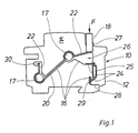
- the side view of an opened residual current circuit breaker 10 is shown, the housing 12 of which is provided on its flat side 14 with an indentation 16 which serves to receive parts of a switching path 20 to be inserted therein. Further details of the residual current circuit breaker 10, which have nothing to do with the invention, have been omitted from this illustration.
- a test button 18 on the operating side of the residual current circuit breaker 10, which can be lowered into the housing 12 when pressed in the direction of the arrow F. For this purpose, it is guided in a guide 27 formed on the housing 12.
- the switching path 20 consists of a spring-elastic first conductor 22 which can be connected to a second electrical conductor 24 by actuating the test button 18.
- One end of the electrical conductor 22 connects to a conductor 30 which at the same time serves as a fixed contact for a contact point (not shown here) and thus connects the switching path 20 to a phase conductor.
- the other end of the first electrical conductor 22 rests on the inward end of the test button 18 and resiliently loads it outwards. A stop formed on the test button, not shown here, prevents the test button 18 from sliding out of the housing 12.
- the second electrical conductor 24, which forms an interruption point 26 together with the first electrical conductor 22, is connected to a connection terminal 28 of the neutral conductor.
- the conductor end of the second electrical conductor 24 is angled and resiliently rests on the connecting terminal 28 or on a conductor 29 rigidly connected to it.
- the second electrical conductor 24 can preferably have an electrical resistance 25, the conductor ends of which, in a commercially available embodiment, are cut to length and shaped accordingly following the contour of the indentation 16.
- pins 17 are arranged on the flat side 14 of the housing 12 within the indentation 16, around which the first electrical conductor 22 is guided. By appropriate dimensioning of the bending radii it is achieved that the first electrical conductor 22 lies closely against the pin 17 and thus ensures the immovability of its position.
- the switching path 20 according to the invention is held exclusively on the housing 12 on the basis of non-positive fixing, the resilient flexibility of the electrical conductors 22, 24 being utilized, conventional connection methods, e.g. B. for soldering or welding, since the frictional contact with the connecting conductors 28, 29, 30 offers sufficient contact.
- a further advantage which is associated with the configuration of the switching path 20 according to the invention, is that no separate spring is required to reset the test button 18, but the reset is sufficient due to the elasticity of the first electrical conductor 22.
Landscapes
- Breakers (AREA)
- Driving Mechanisms And Operating Circuits Of Arc-Extinguishing High-Tension Switches (AREA)
- Keying Circuit Devices (AREA)
Abstract
Description
- Die Erfindung betrifft einen Fehlerstromschutzschalter in einem aus flachen Halbschalen gebildeten Isoliergehäuse in Schmalbauweise mit einem Schaltwerk, mit Anschlußklemmen für den Zugang und den Abgang wenigstens einer Phase und eines Neutralleiters mit einer aus einem Prüfstromkreis und einer an der frontseitigen Schmalseite des Gehäuses angeordneten Prüftaste gebildeten Prüfeinrichtung, wobei der Prüfstromkreis von der phasenseitigen Anschlußklemme über eine vom Schaltwerk betätigte Kontaktstelle zu der Anschlußklemme für den Neutralleiter geführt ist und eine weitere durch Betätigen der Prüftaste schließbare Unterbrechungsstelle aufweist.
- Fehlerstromschutzschalter dienen zur Erfassung von Fehlerströmen, die in elektrischen Leitungsnetzen infolge von Isolationsmängeln oder anderer Fehler bestimmungswidrig gegen fremdes Potential, z. B. Erde, abfließen. Hieraus resultieren Gefahren für den Betreiber der elektrischen Anlage, die es zu verhindern gilt.
- Um die sichere Funktion des Fehlerstromschutzschalters auch nach langer störungsfreier Betriebszeit zu gewährleisten, sind derartige Schaltgeräte mit sogenannten Prüfstromkreisen ausgestattet worden, mittels denen ein Fehlerstrom simuliert werden kann, der zur Auslösung des Fehlerstromschutzschalters führt. Hierdurch soll sichergestellt werden, daß die Funktion des Fehlerstromschutzschalters nicht durch zeit- oder umgebungsbedingte Einflüsse, die zu einer Alterung des Schaltgeräts und seiner Bestandteile führen, dessen sichere Funktion im akuten Ansprechfall gestört ist. Hierzu ist es bekannt, zwischen dem Neutralleiter und einem Phasenleiter eine Schaltstrecke mit einer Unterbrechungsstelle anzuordnen, die mittels eines Tasters schließbar ist. Hierdurch wird ein Teil des durch den Summenstromwandler des Fehlerstromschutzschalters geleiteten Stromes kurzgeschlossen, worauf der Summenstromwandler ein Fehlerstromsignal abgibt, das zur Auslösung des Fehlerstromschutzschalters führt.
- Aus der DE-PS 25 07 497 ist ein Fehlerstromschutzschalter mit Schaltwerk und Prüftaste bekannt geworden, an deren unterem Ende eine mit Festkontaktstücken zusammen wirkende Kontaktfeder angeordnet ist. Die bekannte Prüftaste ist in einem besonderen Bauteil geführt, das an das Schaltwerk angesetzt ist, und dessen elektrische Anschlüsse jeweils separat verlegt sind. Abgesehen von der besonderen Lagerhaltung der für die Prüftaste und ihrer Führung benötigten Teile ist auch der Zusammenbaudes Fehlerstromschutzschalters hierdurch erschwert.
- Ausgehend vom vorstehend genannten Stand der Technik ist es daher Aufgabe der Erfindung, einen kostengünstig herstellbaren Fehlerstromschutzschalter zu schaffen, der einen einfach gestalteten und leicht montierbaren Prüfstromkreis besitzt.
- Die Lösung der Aufgabe ist erfindungsgemäß dadurch gekennzeichnet, daß der Prüfstromkreis in einer in die Flachseite einer Halbschale des Gehäuses eingeformten Ausnehmung angeordnet ist und daß die zur Betätigung des Prüfstromkreises vorgesehene Prüftaste in einer an der Halbschale des Gehäuses angeformten Führung geführt ist.
- Auf diese Weise entfällt der Bedarf an zusätzlichen Bauteilen zur Führung und Halterung des Prüfstromkreises, da mit Herstellung der in jedem Fall erforderlichen Gehäusehalbschale auch gleichzeitig die ein- und angeformten Halte- und Führungsvorrichtungen geschaffen werden.
- Gemäß einer Ausbildung der Erfindung ist vorgesehen, daß der Prüfstromkreis durch einen ersten federelastischen elektrischen Leiter gebildet ist, der an zwei in der Ausnehmung in der Halbschale des Gehäuses vorgesehenen Umlenkpunkten federn verklemmt ist. Er ist dabei so gestaltet, daß er sich mit einem Ende federnd an einen an der Kontaktanordnung zur Unterbrechung des Phasenleiters angeformten Zapfen zwecks elektrisch leitender Verbindung anlegt. Diese Kontaktstelle wird vom Schaltwerk betätigt und bei Auslösung durch den Fehlerstromauslöser geöffnet, so daß der nachfolgende Prüfstromkreis stromlos ist. Das andere Ende des ersten elektrischen Leiters arbeitet mit der Prüftaste derart zusammen, daß diese bei Betätigung die Verbindung des ersten elektrischen Leiters mit einem zweiten elektrischen Leiter herstellt, um so die zwischen beiden Leitern bestehende Unterbrechungsstelle zu schließen. Der zweite elektrische Leiter ist dabei mit einer Anschlußklemme des Neutralleiters verbunden.
- In zweckmäßiger Ausgestaltung der Erfindung kann der zweite elektrische Leiter einen elektrischen Widerstand aufweisen, wobei vorzugsweise ein handelsüblicher Widerstand, z. B. Kohleschicht- oder Drahtwiderstand, vorgesehen ist, dessen. Anschlußenden so geformt sind, daß sie Leitungsführung in der Halbschale des Gehäuses folgen. Auf diese Weise werden zeit- und materialaufwendige Verbindungen, z. B mittels Löten, unnötig, da wegen der Elastizität der elektrischen Leiter eine kraftschlüssige Kontaktierung ausreichende Funktionssicherheit gewährleistet.
- Gemäß einer weiteren bevorzugten Ausgestaltung der Erfindung ist vorgesehen, daß ein Fehlerstromschutzschalter der eingangs genannten Art mit einem Leitungsschutzschalter kombiniert wird, wobei dessen Schalterpol mit dem Phasenleiter des Fehlerstromschutzschalters in Reihe geschaltet ist und beide Schaltgeräte in separaten, nebeneinander angeordneten, aus Halbschalen gebildeten Gehäusen in Schmalbauweise untergebracht sind. Gemäß der Erfindung ist in diesem Fall vorgesehen, daß die Ausnehmung zur Aufnahme der zum Prüfstromkreis gehörigen Teile auf der Außenseite der Halbschale des Gehäuses in diese eingeformt ist und durch das Gehäuse des daran angrenzenden Leitungsschutzschalters verdeckt ist.
- Auch bei der Kombination mit einem Leitungsschutzschalter wird die Kontaktstelle, die den Prüfstromkreis mit dem Phasenleiter verbindet, bei Auslösung des Schaltwerkes geöffnet, so daß der Prüfstromkreis stromlos ist. Hierdurch kann die Zerstörung des im Prüfstromkreis angeordneten Widerstandes vermieden werden.
- Diese und weitere vorteilhafte Ausgestaltungen der Erfindung sind in den Unteransprüchen angegeben.
- Anhand eines in der Zeichnung dargestellten Ausführungsbeispieles sollen die Erfindung, besondere Vorteile und vorteilhafte Ausgestaltungen der Erfindung näher erläutert und beschrieben werden.
- Es zeigt
- die einzige Figur Seitenansicht eines erfindungsgemäßen Fehlerstromschutzschalters.
- In der einzigen Figur ist die Seitenansicht eines geöffneten Fehlerstromschutzschalters 10 gezeigt, dessen Gehäuse 12 auf seiner Flachseite 14 mit einer Einformung 16 versehen ist, welche zur Aufnahme darin einzulegender Teile einer Schaltstrecke 20 dient. Weitere Einzelheiten des Fehlerstromschutzschalters 10, die mit der Erfindung nichts zu tun haben, wurden bei dieser Darstellung weggelassen.
- Ferner ist an der Frontseite, d. h. an der Bedienseite, des Fehlerstromschutzschalters 10 eine Prüftaste 18 angordnet, die bei Druck in Richtung des Pfeiles F in das Gehäuse 12 versenkbar ist. Hierzu ist es in einer am Gehäuse 12 angeformten Führung 27 geführt.
- Die Schaltstrecke 20 besteht aus einem federelastischem ersten Leiter 22, der durch Betätigung der Prüftaste 18 mit einem zweiten elektrischen Leiter 24 verbindbar ist.
- Ein Ende des elektrischen Leiters 22 schließt an einen Leiter 30 an, der gleichzeitig als Festkontakt für eine hier nicht näher gezeigte Kontaktstelle dient und so die Schaltstrecke 20 mit einem Phasenleiter verbindet. Das andere Ende des ersten elektrischen Leiters 22 liegt an dem nach innen weisenden Ende der Prüftaste 18 an und belastet diese federnd nach außen. Ein an der Prüftaste angeformter, hie nicht näher gezeigter Anschlag verhindert ein Herausgleiten der Prüftaste 18 aus dem Gehäuse 12.
- Der zweite elektrische Leiter 24, der gemeinsam mit dem ersten elektrischen Leiter 22 eine Unterbrechungsstelle 26 bildet, ist mit einer Anschlußklemme 28 des Neutralleiters verbunden. Auch hier ist das Leiterende des zweiten elektrischen Leiters 24 abgewinkelt und legt sich federnd an die Anschlußklemme 28 bzw. an einen mit ihr starr verbundenen Leiter 29 federnd an.
- Vorzugsweise kann der zweite elektrische Leiter 24 einen elektrischen Widerstand 25 aufweisen, wobei dessen in handelsüblicher Ausführung mit diesem verbundene Leiterenden der Kontur der Einformung 16 folgend abgelängt und entsprechend geformt sind.
- Zur eindeutigen Lagefixierung des ersten elektrischen Leiters 22 dienen jeweils an die Flachseite 14 des Gehäuses 12 innerhalb der Einformung 16 angeordnete Zapfen 17, um welche der erste elektrische Leiter 22 herumgeführt ist. Durch entsprechende Bemessung der Biegeradien wird hierbei erreicht, daß der erste elektrische Leiter 22 sich eng an die Zapfen 17 anlegt und so die Unverrückbarkeit seiner Lage gewährleistet.
- Da die erfindungsgemäße Schaltstrecke 20 ausschließlich aufgrund kraftschlüssiger Fixierung am Gehäuse 12 gehalten is, wobei die federelastische Biegsamkeit der elektrischen Leiter 22, 24 ausgenützt wird, kann auf herkömmliche Verbindungsverfahren, z. B. für Löten bzw. Schweißen verzichtet werden, da der kraftschlüssige Kontakt mit den Anschlußleitern 28, 29, 30 ausreichenden Kontakt bietet.
- Ein weiterer Vorteil, der sich mit der erfindungsgemäßen Ausgestaltung der Schaltstrecke 20 verbindet, besteht darin, daß zur Rückstellung der Prüftaste 18 keine separate Feder erforderlich ist, sondern die Rückstellung durch die Elastizität des ersten elektrischen Leiters 22 ausreicht.
Claims (8)
Applications Claiming Priority (2)
| Application Number | Priority Date | Filing Date | Title |
|---|---|---|---|
| DE3825479 | 1988-07-27 | ||
| DE3825479A DE3825479A1 (de) | 1988-07-27 | 1988-07-27 | Fehlerstromschutzschalter |
Publications (3)
| Publication Number | Publication Date |
|---|---|
| EP0352680A2 true EP0352680A2 (de) | 1990-01-31 |
| EP0352680A3 EP0352680A3 (de) | 1991-08-07 |
| EP0352680B1 EP0352680B1 (de) | 1995-02-01 |
Family
ID=6359653
Family Applications (1)
| Application Number | Title | Priority Date | Filing Date |
|---|---|---|---|
| EP89113536A Expired - Lifetime EP0352680B1 (de) | 1988-07-27 | 1989-07-22 | Fehlerstromschutzschalter |
Country Status (3)
| Country | Link |
|---|---|
| EP (1) | EP0352680B1 (de) |
| AT (1) | ATE118119T1 (de) |
| DE (2) | DE3825479A1 (de) |
Cited By (1)
| Publication number | Priority date | Publication date | Assignee | Title |
|---|---|---|---|---|
| WO2005017935A1 (de) * | 2003-08-19 | 2005-02-24 | Moeller Gebäudeautomation KG | Prüftastermodul |
Families Citing this family (1)
| Publication number | Priority date | Publication date | Assignee | Title |
|---|---|---|---|---|
| DE10034362A1 (de) * | 2000-07-14 | 2002-01-24 | Abb Patent Gmbh | Leitungsschutz- oder Fehlerstromschutzschalter |
Family Cites Families (4)
| Publication number | Priority date | Publication date | Assignee | Title |
|---|---|---|---|---|
| DE2733837C2 (de) * | 1977-07-27 | 1979-08-30 | Licentia Patent-Verwaltungs-Gmbh, 6000 Frankfurt | Fehlerstromschutzschalter mit Prüftaste |
| DE2834327C2 (de) * | 1978-08-04 | 1983-01-13 | Heinrich Kopp Gmbh & Co Kg, 8756 Kahl | Elektrischer Vollschutzschalter |
| DE3032826C2 (de) * | 1980-08-30 | 1985-11-07 | Licentia Patent-Verwaltungs-Gmbh, 6000 Frankfurt | Fehlerstromschutzschalter mit einer Prüftaste zum Einschalten eines Widerstandes in einen Prüfstromkreis |
| US4513268A (en) * | 1983-12-14 | 1985-04-23 | General Electric Company | Automated Q-line circuit breaker |
-
1988
- 1988-07-27 DE DE3825479A patent/DE3825479A1/de not_active Withdrawn
-
1989
- 1989-07-22 EP EP89113536A patent/EP0352680B1/de not_active Expired - Lifetime
- 1989-07-22 AT AT89113536T patent/ATE118119T1/de not_active IP Right Cessation
- 1989-07-22 DE DE58908960T patent/DE58908960D1/de not_active Expired - Fee Related
Cited By (3)
| Publication number | Priority date | Publication date | Assignee | Title |
|---|---|---|---|---|
| WO2005017935A1 (de) * | 2003-08-19 | 2005-02-24 | Moeller Gebäudeautomation KG | Prüftastermodul |
| AU2004265697B2 (en) * | 2003-08-19 | 2009-02-26 | Moeller Gebaudeautomation Gmbh | Test pushbutton module |
| CN1836302B (zh) * | 2003-08-19 | 2011-01-26 | 穆勒建筑物自动化两合公司 | 测试探针模块 |
Also Published As
| Publication number | Publication date |
|---|---|
| EP0352680B1 (de) | 1995-02-01 |
| DE58908960D1 (de) | 1995-03-16 |
| DE3825479A1 (de) | 1990-02-01 |
| ATE118119T1 (de) | 1995-02-15 |
| EP0352680A3 (de) | 1991-08-07 |
Similar Documents
| Publication | Publication Date | Title |
|---|---|---|
| DE102015101893B4 (de) | Leiteranschlussklemme | |
| DE4217913A1 (de) | Kombinierte kabelschuh- und verbindungsanordnung fuer einen elektrischen schalter | |
| DE3525085A1 (de) | Einrichtung fuer ein kraftfahrzeug | |
| DE2547344A1 (de) | Fehlerstromschutzschalter in steckdosenausfuehrung | |
| EP0170161A2 (de) | Installationsgerät für Sammelschienensysteme | |
| DE10003267C2 (de) | Stromkreisunterbrechereinrichtung | |
| DE102022115025A1 (de) | Vorrichtung zum Schutz gegen Überspannungen umfassend einem Sensor zur Strommessung | |
| DE69420923T2 (de) | Differentialschutzblock mit Kabeldurchgang | |
| DE69412149T2 (de) | Differentialschutzeinheit mit auf Funktion testbarer Untereinheit | |
| EP0582975A1 (de) | Automatischer Brandmelder | |
| DE10030954A1 (de) | Stromverteiler | |
| DE3023499A1 (de) | Elektrisches installationsgeraet | |
| EP0352680B1 (de) | Fehlerstromschutzschalter | |
| DE19537585C1 (de) | Anschlußelement zum Anschließen des Kabelschirmes eines Schirmkabels | |
| DE3877729T2 (de) | Anordnung zum erzielen einer kontaktfunktion in einem pruefsystem fuer relaisschutzausruestungen. | |
| DE3147674C2 (de) | Fassung für ein Miniaturrelais | |
| EP0494427B1 (de) | Elektrizitätszähler | |
| DE2618288B2 (de) | Installations-Selbstschalter | |
| EP2983191B1 (de) | Anordnung zur erfassung von störlichtbögen in einem niederspannungsnetz | |
| DE3884179T2 (de) | Steuerrelais mit steckbaren Messfühler. | |
| DE3813403C2 (de) | Ortsveränderlicher Differenzstromschalter | |
| DE3610451A1 (de) | Elektrisches installationsgeraet | |
| DE60118431T2 (de) | Elektrischer pol für einen niederspannungs-unterbrecherschalter | |
| DD297286A5 (de) | Schutzeinrichtung fuer einen verteiler in einer telekommunikationsanlage | |
| DE102017203205A1 (de) | Kabelbrückenmodul zur flexiblen verknüpfung von verbindungsklemmen |
Legal Events
| Date | Code | Title | Description |
|---|---|---|---|
| PUAI | Public reference made under article 153(3) epc to a published international application that has entered the european phase |
Free format text: ORIGINAL CODE: 0009012 |
|
| AK | Designated contracting states |
Kind code of ref document: A2 Designated state(s): AT BE CH DE ES FR GB IT LI NL |
|
| PUAL | Search report despatched |
Free format text: ORIGINAL CODE: 0009013 |
|
| AK | Designated contracting states |
Kind code of ref document: A3 Designated state(s): AT BE CH DE ES FR GB IT LI NL |
|
| 17P | Request for examination filed |
Effective date: 19910904 |
|
| 17Q | First examination report despatched |
Effective date: 19940121 |
|
| GRAA | (expected) grant |
Free format text: ORIGINAL CODE: 0009210 |
|
| AK | Designated contracting states |
Kind code of ref document: B1 Designated state(s): AT BE CH DE ES FR GB IT LI NL |
|
| PG25 | Lapsed in a contracting state [announced via postgrant information from national office to epo] |
Ref country code: IT Free format text: LAPSE BECAUSE OF FAILURE TO SUBMIT A TRANSLATION OF THE DESCRIPTION OR TO PAY THE FEE WITHIN THE PRE;WARNING: LAPSES OF ITALIAN PATENTS WITH EFFECTIVE DATE BEFORE 2007 MAY HAVE OCCURRED AT ANY TIME BEFORE 2007. THE CORRECT EFFECTIVE DATE MAY BE DIFFERENT FROM THE ONE RECORDED.SCRIBED TIME-LIMIT Effective date: 19950201 Ref country code: BE Effective date: 19950201 Ref country code: NL Effective date: 19950201 Ref country code: GB Effective date: 19950201 Ref country code: ES Free format text: THE PATENT HAS BEEN ANNULLED BY A DECISION OF A NATIONAL AUTHORITY Effective date: 19950201 Ref country code: FR Effective date: 19950201 |
|
| REF | Corresponds to: |
Ref document number: 118119 Country of ref document: AT Date of ref document: 19950215 Kind code of ref document: T |
|
| REF | Corresponds to: |
Ref document number: 58908960 Country of ref document: DE Date of ref document: 19950316 |
|
| EN | Fr: translation not filed | ||
| NLV1 | Nl: lapsed or annulled due to failure to fulfill the requirements of art. 29p and 29m of the patents act | ||
| PG25 | Lapsed in a contracting state [announced via postgrant information from national office to epo] |
Ref country code: AT Effective date: 19950722 |
|
| PG25 | Lapsed in a contracting state [announced via postgrant information from national office to epo] |
Ref country code: LI Effective date: 19950731 Ref country code: CH Effective date: 19950731 |
|
| GBV | Gb: ep patent (uk) treated as always having been void in accordance with gb section 77(7)/1977 [no translation filed] |
Effective date: 19950201 |
|
| PLBE | No opposition filed within time limit |
Free format text: ORIGINAL CODE: 0009261 |
|
| STAA | Information on the status of an ep patent application or granted ep patent |
Free format text: STATUS: NO OPPOSITION FILED WITHIN TIME LIMIT |
|
| 26N | No opposition filed | ||
| REG | Reference to a national code |
Ref country code: CH Ref legal event code: PL |
|
| PGFP | Annual fee paid to national office [announced via postgrant information from national office to epo] |
Ref country code: DE Payment date: 20060714 Year of fee payment: 18 |
|
| PG25 | Lapsed in a contracting state [announced via postgrant information from national office to epo] |
Ref country code: DE Free format text: LAPSE BECAUSE OF NON-PAYMENT OF DUE FEES Effective date: 20080201 |