EP0352686A1 - Vorrichtung zum Öffnen und Füllen von Briefumschlägen - Google Patents
Vorrichtung zum Öffnen und Füllen von Briefumschlägen Download PDFInfo
- Publication number
- EP0352686A1 EP0352686A1 EP89113555A EP89113555A EP0352686A1 EP 0352686 A1 EP0352686 A1 EP 0352686A1 EP 89113555 A EP89113555 A EP 89113555A EP 89113555 A EP89113555 A EP 89113555A EP 0352686 A1 EP0352686 A1 EP 0352686A1
- Authority
- EP
- European Patent Office
- Prior art keywords
- fingers
- axis
- finger
- opening
- opening device
- Prior art date
- Legal status (The legal status is an assumption and is not a legal conclusion. Google has not performed a legal analysis and makes no representation as to the accuracy of the status listed.)
- Granted
Links
- 238000003780 insertion Methods 0.000 claims description 20
- 230000037431 insertion Effects 0.000 claims description 20
- 230000008878 coupling Effects 0.000 claims description 6
- 238000010168 coupling process Methods 0.000 claims description 6
- 238000005859 coupling reaction Methods 0.000 claims description 6
- 230000009471 action Effects 0.000 claims description 4
- 230000000717 retained effect Effects 0.000 abstract description 6
- 230000014759 maintenance of location Effects 0.000 description 3
- 230000007246 mechanism Effects 0.000 description 3
- 238000012423 maintenance Methods 0.000 description 2
- 208000029278 non-syndromic brachydactyly of fingers Diseases 0.000 description 2
- 238000005096 rolling process Methods 0.000 description 2
- 238000012546 transfer Methods 0.000 description 2
- 208000031968 Cadaver Diseases 0.000 description 1
- 230000005540 biological transmission Effects 0.000 description 1
- 238000001514 detection method Methods 0.000 description 1
- 230000000694 effects Effects 0.000 description 1
- 238000004519 manufacturing process Methods 0.000 description 1
- 238000012986 modification Methods 0.000 description 1
- 230000004048 modification Effects 0.000 description 1
- 230000003287 optical effect Effects 0.000 description 1
- 230000008520 organization Effects 0.000 description 1
- 238000013021 overheating Methods 0.000 description 1
- 230000007704 transition Effects 0.000 description 1
- 238000011144 upstream manufacturing Methods 0.000 description 1
Images

Classifications
-
- B—PERFORMING OPERATIONS; TRANSPORTING
- B43—WRITING OR DRAWING IMPLEMENTS; BUREAU ACCESSORIES
- B43M—BUREAU ACCESSORIES NOT OTHERWISE PROVIDED FOR
- B43M3/00—Devices for inserting documents into envelopes
- B43M3/04—Devices for inserting documents into envelopes automatic
- B43M3/045—Devices for inserting documents into envelopes automatic for envelopes with only one flap
Definitions
- the present invention relates to machines for inserting folds into envelopes. It relates more particularly in such machines to a device for opening the body of successive envelopes with a view to the insertion of a fold in each of these envelopes.
- means for advancing envelopes ensure the supply and presentation of the successive envelopes to be loaded in a defined loading position, facing a fold path .
- Each of the folds is advanced on its way then inserted into the envelope while waiting in its loading position. After loading, the envelope concerned is ejected.
- the envelope flap is unfolded.
- the envelope placed in its loading position has its flap retained unfolded so as not to interfere with the execution of the fold insertion operation.
- opening fingers of the body of the envelope mounted normally erased in front of the envelope in the loading position, are actuated in the open position to partially insert into the body of the envelope and open it before inserting the fold.
- These fingers are generally mounted at the end of an actuating arm controlled in synchronism with the progress of an insertion cycle, for erasing the fingers and placing them in the open position.
- the object of the present invention is precisely to produce a device for opening the body of the envelopes to be loaded, of very simple production and of mounting in an inserting machine made very easy, and not having with its control mechanism. a very small footprint.
- a device for opening the body of envelopes for loading returning to an insertion machine in which each envelope to be loaded is maintained in a so-called loading position opposite a fold path
- said device comprising opening fingers coupled to actuation means themselves coupled to control means, to ensure that the opening fingers are placed in the retracted position and in the open position, facing the envelope in said loading position, and being characterized in that it comprises a pre-assembled assembly formed on an axis known as the axis of the fingers, with said opening fingers mounted free in rotation on said axis of the fingers and with said axis of the fingers equipped with first means for longitudinal positioning, for each finger, and second elastic stop means extending on the same side of said axis of the fingers, for each finger, and in that it further comprises a pl guide guide mounted opposite said assembly by opposing the action of said second means on the fingers and by guiding the fingers against one of its faces, when the fingers are actuated from one of said positions to the 'other.
- the guide plate is a plate coupling said path of the folds to the envelope in said loading position, in the insertion machine, said guide plate partially covering said assembly.
- said axis of the fingers comprises, in addition, at least one sliding shoe under said guide plate, for maintaining the orientation of said axis of the fingers.
- said axis of the fingers carries, in addition, two longitudinal slides in which it slides and which allow the direct mounting of said assembly in the insertion machine.
- two rings and a spiral spring ensure the longitudinal positioning of each opening finger on the axis of the fingers and one of the terminal strands of the spring extends laterally opposite the opening finger concerned and at its end folded under the finger to ensure its retention.
- FIG. 1 the general organization of an envelope loading station has been illustrated, in an inserting machine equipped with a device for opening the body of the envelopes according to the present invention.
- 1 indicates a path of empty envelopes to be loaded and 2 a path of the folds.
- the arrow 1A indicates the advance of an empty envelope to be loaded, on the path 1, for its presentation and its maintenance in a defined loading position, facing the path 2 of the folds.
- the arrow 2A translates the advance of a fold on the path 2, for its transfer to the envelope awaiting loading and its insertion into the envelope.
- a first set of rollers 3 and a first associated set of counter rollers 4 contribute to the advance of each envelope to its loading position and ensure that it is held in this position during loading.
- a pair of second sets of pressure rollers 5 and 6, slightly upstream on path 1, ensures the retention of the envelope flap previously unfolded when the envelope is in its loading position. Suitable means not illustrated make it possible to unfold the envelope flap during the advance of the envelope on the path 1.
- a motor 7, known as the envelope motor, ensures the advance of each envelope. It is coupled in particular to the first set of rollers 3 which it drives along arrow 3A and stops when the envelope is in the loading position.
- the loading position corresponds to the passage of the body of the envelope between the first sets of rollers and counter-rollers 3 and 4, for which the junction line between the body of the envelope and its unfolded flap is between these first sets of rollers and counter-rollers 3 and 4.
- a pair of third sets of rollers 8 and 9 contribute to the advance of each of the folds on path 2, which is to be inserted in the envelope awaiting loading.
- These sets of rollers 8 and 9 are mounted elastically under pressure on the outlet of path 2.
- a fold guide plate 10 is mounted between the sets of rollers 8 and counter rollers 4.
- a counter plate 11 is associated with it between the sets of rollers 9 and 3.
- a motor 12 called the fold motor, ensures the advance of the folds on the path 2. It is shown coupled to the set of rollers 8 mounted under the outlet of the path 2. It can also be coupled to the set of rollers 9. An arrow 8A translates the drive of the set of rollers 8, provided by the motor 12 when the latter is ordered.
- Opening fingers 13 of the casing body are mounted between the sets of rollers 3 and counter-rollers 4 and the sets of rollers 8 and 9. They are normally erased at the front of the sets of rollers and counter-rollers 3 and 4. They are actuated according to arrow 13F in the open position of the body of the envelope on standby in its loading position.
- Such a general provision is in as such known.
- the embodiment of the opening device according to the invention, which comprises these fingers 13, will be specified below.
- the first set of counter rollers 4 is mounted retractable under the first set of rollers 3.
- a cam 14 is assigned to control the first set of counter rollers 4 in a pressure position against the first set of rollers 3 and in a retracted position.
- Another cam 15 is assigned to control the opening fingers 13 in their retracted position and in their opening position.
- These two cams 14 and 15 are mounted on the same drive shaft 16.
- the arrow 16A translates the drive of this drive shaft 16.
- a drive motor, not shown, drives it.
- the two cams 14 and 15 are initially calibrated relative to each other for the suitable commands which they carry out in synchronism with the progress of an insertion cycle.
- a pair of arms 20 carries the set of counter-rollers 4. It is mounted articulated about an axis 20A which is formed by the axis of the set of rollers 8 in advance of the folds. These arms carry a roller 21 for rolling on the cam 14; the roller 21 is held in abutment on the cam 14 by elastic means not shown.
- An arrow 20F translates the pivoting of the pair of arms 20A, for placing the set of counter-rollers 4 in the retracted position.
- levers 22 carries the opening fingers 13. These levers are articulated around a terminal axis 22A, opposite the opening fingers. They carry a rolling roller 23 on the cam 15.
- the cam 14 has on its periphery two profiles 14A and 14C, centered opposite each other substantially, for the control of setting the pressure of the set of counter rollers 4; it has, in addition, two other sections 14B and 14D, on one side and on the other, between the first two sections, for the command to set the backlash clearance position rollers 4.
- the cam 15 has only two sections 15A and 15B on its periphery, for the control in the retracted position and in the open position, respectively, of the fingers 13.
- a disc 18 with a notch 18A is mounted with the cams 14 and 15 on the motor shaft 16. It is associated with a detector shown diagrammatically at 19 mounted on an optical fork on the disc 18 to detect the notch 18A. This disc 18 and detector 19 assembly then provides reference position detection for the camshaft 14 and 15.
- the set of counter-rollers 3 is also coupled to the set of rollers 8 in advance of the folds, for its drive with it.
- the set of counter-rollers 4 is for this purpose mounted on a freewheel mechanism 26.
- An arrow 4A illustrates the rotation drive of the set of counter-rollers 4, either by friction against the set of rollers 3 then driven or by the coupling carried out on the set of rollers 8 in advance of the folds.
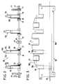
- FIGS. 2 and 3 are schematic top views showing separately a pre-assembled assembly with opening fingers and the aforementioned guide plate 10, this plate cooperating with this assembly and belonging with it to the opening device.
- the opening finger assembly is generally designated by the reference 30. It is mounted directly between the two lateral flanges such as 31 of the machine, on which it is retained and is partially covered by the guide plate 10 positioned relatively to this set and attached to the flanges.
- This assembly 30 with opening fingers is described with reference to FIG. 2.
- the references of its elements, which are visible in FIG. 1, have simply been reported in this FIG. 1.
- the assembly 30 is formed on an axis 35 said axis of the fingers. It has an arrangement which has symmetry with respect to a transverse plane intersecting the axis of the fingers in the middle of its length.
- the four fingers 13A and 13B are mounted to rotate freely on the axis of the fingers 35. These fingers are positioned longitudinally on the axis 35 each between two rings 36 and 37.
- the two positioning rings relating to the same finger have between them a spacing greater than the width of the finger.
- a spring 38 is wound around the axis of the fingers 35, between this finger and one of the corresponding rings, which is the ring 37. This spring ensures with the two rings the positioning longitudinal of each finger. It has one of its ends locked in the ring 37, by suitable retaining means not shown. Its other end extends at the front of the axis, laterally opposite the finger concerned, and at its end 38A folded under this finger which forms an elastic support stop for this finger.
- the ends of the axis of the fingers 35 are each mounted in a longitudinal slide 40.
- Two circlips 41 each on the outer side of the slide considered, ensure the retention of these slides on the axis of the fingers 35.
- the axis of the fingers 35 carries, in addition, a central pad 45.
- This pad has the shape of a small block of rectangular section, the flat and rectangular upper face of which forms a sliding surface for the assembly 30, opposite a reference piece, in this case the aforementioned guide plate 10. It is blocked by a screw 46, or the like, on the axis of the fingers, without freedom of rotation; it constitutes an orientation pad for the axis of the fingers 35.
- Figure 3 shows the aforementioned guide plate 10 which cooperates with the assembly 30 of Figure 2.
- the plate 10 is mounted like the assembly 30 between the side flanges such as 31 of the machine ( Figure 1), coming to cover partially the assembly 30.
- the aforementioned axis 35 and the opening fingers have been identified ture 13A, 13B of the assembly 30 of FIGS. 1 and 2 and the counter-rollers 4 of FIG. 1.
- This plate is flat, apart from its rear edge 10A which is slightly folded.
- the front part of this guide plate 10 has four notches 50 for the four opening fingers 13A, 13B of the assembly 30, which have been shown in dotted lines.
- the terminal part of each of the fingers is flush with the plate through its notch.
- This same front part of the guide plate 10 also has three other notches 51, less deep than the notches 50 and situated in the gaps left between the notches 50.
- These notches 51 correspond to the first set of counter-rollers 4 mentioned above (FIG. 1); the three counter-rollers 4 of this first set each come into slight projection on the level of the guide plate, through one of the corresponding notches 51, when this first set of counter-rollers 4 is in the pressure position.
- the front edge 10B of the plate is more prominent in its middle part. It has a largely open and inverted V-shaped profile, the two branches and the edge of which are cut by the notches 50, 51.
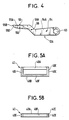
- FIG. 4 being a profile view on an enlarged scale of the short fingers 13A of FIG. 2.
- the long fingers 13B are practically identical to the short fingers 13A, only their end portion has been made slightly longer. They are therefore neither illustrated nor described separately.
- Each of the opening fingers 13A is constituted by an elongated profile. It has a terminal bore 53 transverse to the elongated profile, for its free mounting in rotation on the axis of the fingers. This bore has a diameter very slightly greater than that of the axis of the fingers.
- This profile has two main parts 54 and 55 separated by a small middle transition part 56.
- the part 54 is that which has the bore 53.
- the part 55 is that terminal of the finger considered mounted on the axis of the fingers. They have their upper face 54A and 55A which is substantially horizontal, but with the level of the face 55A slightly raised relative to that of the face 54A.
- the upper face 56A of the intermediate middle part forms an inclined connecting surface.
- the lower faces of these parts 54, 55 and 56 are substantially parallel to the respective upper faces and have not been referenced. Only the tip of the finger, on part 55, has its rounded underside; this end is identified by the reference 55B, it forms a sharp angle and has a reduced thickness for ease of insertion of the finger into the envelope and then increasing for good opening of the envelope.
- the fingers 13A or 13B also have lateral chamfers 55C on their terminal part 55, making the lower face of this terminal part narrower than its upper face. They also have a rounded slope 55D on the underside of their tip 55B.
- the upper face 54A of the part 54 of each finger constitutes the finger abutment plane against the underside of the guide plate 10, against the action exerted by the spring 38 on this finger. It also forms the guide plane of each finger under the plate 10, when the fingers are actuated from their retracted position to their open position and vice versa. In addition, when the fingers are actuated in the open position, this face 54A progressively escapes in the corresponding notch 50, to make it possible to accentuate the effect of the spring 38 and to cause a slight pivoting upwards. from part 55 of each finger.
- the lower inclined face of the intermediate part 56 is received on the support end 38A of the spring. It thus opposes any significant sliding of the support end 38A of this spring.
- FIG. 5 one of the slides 40 of the above-mentioned assembly has been shown, seen from the front in 5A and from above in 5B.
- This slide 40 forms a rectangular window in which the axis of the fingers is held while being able to slide.
- This slide guides the axis of the fingers 35, when the assembly 30 is mounted in place on the machine; it also allows the assembly of the assembly 30 on the insertion machine ( Figure 1).
- Each slide 40 has a large upper side 40A, another lower 40B and two identical side sides 40C. It has on the length of each of its lateral sides a groove 40E and on that of its only lower longitudinal side 40B another groove 40F.
- each lateral flange 31 for the corresponding slide 40.
- This housing is open on its upper edge; each of its three other edges constitutes or has a rib on which the corresponding groove of the slide 40 is inserted.
- the assembly 30, which has its various elements pre-assembled on the axis of the fingers 35, is equipped to be directly mounted, in a very simple manner, on the machine.
- each of the levers 22 is constituted by an arm articulated at the bottom of the machine and the opposite end of which forms a fork 22B for direct reception of the end parts of the axis of the fingers 35.
- the axis of the fingers 35 is retained in this fork 22B by the guide plate 10.
- This same guide plate 20 also closes the upper edge of the housing of each slide 40 provided in the flanges and then prevents any release of this slide.
- Each of the levers extends over the external face of each of the lateral flanges 31 of the machine.
- the outside of each of these levers, opposite the opposite face of the flange carries a short, projecting cylindrical finger, which constitutes the aforementioned roller 23.
- This roller 23 is engaged in a path which constitutes the cam 15.
- the cam path 15 is therefore defined in the front face of a control disc 17, which is opposite the side flange 31 concerned of the machine.
- the cam 14 for controlling the first set of counter rollers 4 then consists of the periphery of a hub of the control disc 17. This arrangement makes it possible to produce the two cams 14 and 15 on the same part 17.
- the opening device according to the invention is made easy to produce, to assemble in the insertion machine and to disassemble. It does not require any further adjustment. It is very compact, being placed under the guide plate 10.
- This plate 10 then has the double function of guiding the plies on its upper face, by coupling the path of the plies to the envelope in the loading position, and guiding the opening fingers 13 and constant maintenance of the orientation of their axis 35 for the assembly 30.
- the assembly 30 has very low inertia.
- the present invention has been described with reference to the exemplary embodiment illustrated in the drawings. It is obvious that it is possible to make modifications to it in detail and / or to replace certain means by other equivalents, without going beyond the ambit of the invention.
- the elastic stop means for the fingers produced by spiral springs one of the strands of which forms this stop can be produced by any other means opposing the complete rotation of the fingers on the axis of the fingers and the action of plate 10 on the fingers.
- the slides 40 carried by the axis of the fingers 35 of the assembly 30, considered not yet mounted on the machine, can be retained laterally on the guide plate instead of being retained on the flanges of the machine, the plate guide and the assembly 30 both assembled can then be fixed on the machine.
- the function of maintaining the orientation of the axis of the fingers, performed by the central shoe 45 can also be provided, in addition or as a variant, by the terminal portions from the axis these fingers, by giving these terminal portions received in the slides a rectangular section or by forming flats there.
- the longitudinal retaining rings 36, 37 can also perform this function of maintaining the orientation of the axis of the fingers 35.
Landscapes
- Supplying Of Containers To The Packaging Station (AREA)
Applications Claiming Priority (2)
| Application Number | Priority Date | Filing Date | Title |
|---|---|---|---|
| FR8810122A FR2634731B1 (fr) | 1988-07-27 | 1988-07-27 | Dispositif d'ouverture de corps d'enveloppes pour leur chargement |
| FR8810122 | 1988-07-27 |
Publications (2)
| Publication Number | Publication Date |
|---|---|
| EP0352686A1 true EP0352686A1 (de) | 1990-01-31 |
| EP0352686B1 EP0352686B1 (de) | 1993-10-06 |
Family
ID=9368830
Family Applications (1)
| Application Number | Title | Priority Date | Filing Date |
|---|---|---|---|
| EP89113555A Expired - Lifetime EP0352686B1 (de) | 1988-07-27 | 1989-07-24 | Vorrichtung zum Öffnen und Füllen von Briefumschlägen |
Country Status (4)
| Country | Link |
|---|---|
| US (1) | US4944137A (de) |
| EP (1) | EP0352686B1 (de) |
| DE (1) | DE68909706T2 (de) |
| FR (1) | FR2634731B1 (de) |
Families Citing this family (12)
| Publication number | Priority date | Publication date | Assignee | Title |
|---|---|---|---|---|
| US5301935A (en) * | 1991-07-15 | 1994-04-12 | Duplo Corporation | Apparatus for inserting and sealing envelopes with temporary storage pocket |
| US5168689A (en) * | 1991-10-24 | 1992-12-08 | Pitney Bowes Inc. | Envelope stuffing apparatus with adjustable deck for handling different styled envelopes |
| US5447015A (en) * | 1993-11-01 | 1995-09-05 | Pitney Bowes Inc. | High speed insertion device |
| US5374044A (en) * | 1993-11-01 | 1994-12-20 | Pitney Bowes Inc. | Vacuum drum document handling system for an insertion device |
| US5428944A (en) * | 1993-11-01 | 1995-07-04 | Pitney Bowes Inc. | Envelope transport, deskew and stop apparatus |
| US5675959A (en) * | 1996-01-18 | 1997-10-14 | Pitney Bowes Inc. | Opening fingers for envelope inserting apparatus |
| US7155878B2 (en) * | 2004-08-31 | 2007-01-02 | Pitney Bowes Inc. | Device for opening the throat of an envelope in an insertion station |
| NL1027933C2 (nl) * | 2004-12-31 | 2006-07-03 | Neopost Sa | Inrichting voor het couverteren van documenten. |
| EP2123475B1 (de) * | 2008-05-20 | 2013-10-09 | Neopost Technologies | Verfahren und Vorrichtung zum Einlegen einer Postsendung in einen Umschlag und Befeuchten der Umschlagklappe |
| EP2123474B1 (de) * | 2008-05-20 | 2011-08-24 | Neopost Technologies | Verfahren und Vorrichtung zum Einlegen einer Postsendung in einen Umschlag |
| EP2903920B1 (de) * | 2012-10-03 | 2017-12-06 | Amazon Technologies, Inc. | Funktionelle schalen zur handhabung von produkten in einer fördertechnikanlage |
| EP2746060B1 (de) * | 2012-12-20 | 2016-04-27 | BÖWE SYSTEC GmbH | Kuvertierer und Verfahren zum Öffnen eines Kuvertmunds eines entlang eines Kuvertkanals transportierten Kuverts |
Citations (3)
| Publication number | Priority date | Publication date | Assignee | Title |
|---|---|---|---|---|
| US2736999A (en) * | 1950-05-25 | 1956-03-06 | Pitney Bowes Inc | Envelope stuffing machine |
| US2835090A (en) * | 1953-08-25 | 1958-05-20 | Pitney Bowes Inc | Workpiece stripping device |
| DE3137033A1 (de) * | 1980-09-17 | 1982-04-15 | Pitney Bowes, Inc., 06926 Stamford, Conn. | Vorrichtung zum fuellen von briefumschlaegen |
Family Cites Families (3)
| Publication number | Priority date | Publication date | Assignee | Title |
|---|---|---|---|---|
| US2766569A (en) * | 1952-10-01 | 1956-10-16 | Pitney Bowes Inc | Mail treating and inserting device |
| US2914895A (en) * | 1959-02-13 | 1959-12-01 | Pitney Bowes Inc | Envelope stuffing machine |
| NL7708799A (nl) * | 1977-08-10 | 1979-02-13 | Bell Telephone Mfg | Envelop-openinrichting en envelop-vulmachine welke deze gebruikt. |
-
1988
- 1988-07-27 FR FR8810122A patent/FR2634731B1/fr not_active Expired - Lifetime
-
1989
- 1989-07-17 US US07/380,343 patent/US4944137A/en not_active Expired - Lifetime
- 1989-07-24 DE DE89113555T patent/DE68909706T2/de not_active Expired - Fee Related
- 1989-07-24 EP EP89113555A patent/EP0352686B1/de not_active Expired - Lifetime
Patent Citations (3)
| Publication number | Priority date | Publication date | Assignee | Title |
|---|---|---|---|---|
| US2736999A (en) * | 1950-05-25 | 1956-03-06 | Pitney Bowes Inc | Envelope stuffing machine |
| US2835090A (en) * | 1953-08-25 | 1958-05-20 | Pitney Bowes Inc | Workpiece stripping device |
| DE3137033A1 (de) * | 1980-09-17 | 1982-04-15 | Pitney Bowes, Inc., 06926 Stamford, Conn. | Vorrichtung zum fuellen von briefumschlaegen |
Also Published As
| Publication number | Publication date |
|---|---|
| FR2634731B1 (fr) | 1990-09-14 |
| DE68909706D1 (de) | 1993-11-11 |
| DE68909706T2 (de) | 1994-02-03 |
| US4944137A (en) | 1990-07-31 |
| EP0352686B1 (de) | 1993-10-06 |
| FR2634731A1 (fr) | 1990-02-02 |
Similar Documents
| Publication | Publication Date | Title |
|---|---|---|
| EP0538106B1 (de) | Motorisiertes Fensterrolle für gebogenes Fenster | |
| EP0352686B1 (de) | Vorrichtung zum Öffnen und Füllen von Briefumschlägen | |
| FR2601303A1 (fr) | Dispositif de manoeuvre pour un toit ouvrant de vehicule dont le levier d'actionnement est relie avec le premier element de glissement. | |
| FR2585297A1 (fr) | Dispositif pour deplacer en va-et-vient un objet tel que la glace d'une fenetre d'un vehicule | |
| FR2733000A1 (fr) | Perfectionnements aux dispositifs de fermeture a enroulement | |
| EP0102301A2 (de) | Maschine und Arbeitsweise zum Herstellen von Kunststoffbeuteln mit Reissverschluss und Vorrichtung zum Anbringen desselben | |
| FR2725167A1 (fr) | Perfectionnements aux articulations des dossiers de sieges de vehicules | |
| WO2005014962A2 (fr) | Verrou destine a relier deux panneaux d’une strcuture d’aeroplane | |
| EP0796573B1 (de) | Gelenklager für Handtasche und ähnliches Handgepäck | |
| EP0840857A1 (de) | Automatische rastvorrichtung zur führung eines um ein achse schwenkbaren bauteils gegen ein um dieselbe achse festes bauteil | |
| FR2673744A1 (fr) | Dispositif de guidage de pieces de monnaie. | |
| EP1470012B1 (de) | Kofferraumdeckel für ein cabriofahrzeug mit faltverdeck | |
| FR2467612A1 (fr) | Frein de ski | |
| EP0467741B1 (de) | Kontinuierliche Heftklammervorrichtung mit feststehendem Klammerbett und mit einer solchen Vorrichtung versehene Heftklammermaschine | |
| FR2865235A1 (fr) | Joue pour un dispositif obturateur de coffre-tunnel | |
| FR2634692A1 (fr) | Dispositif d'insertion de plis dans des enveloppes | |
| FR3039131B1 (fr) | Trappe arriere de case de train d'atterrissage comprenant un orifice de passage d'air et un organe d'obturation de celui-ci | |
| FR2538053A1 (fr) | Dispositif de verrouillage d'un element monte a pivotement sur un support fixe, notamment un cendrier monte pivotant sur une planche de bord d'un vehicule automobile | |
| EP0708871B1 (de) | Fenster nach jalousie-art | |
| EP0636572B1 (de) | Hebebock, insbesondere Wagenheber | |
| FR2862182A1 (fr) | Dispositif de dosage et de distribution de graines pour semoir | |
| EP0775605B1 (de) | Sonnenschutzrolle mit Entfaltungsmechanismus durch Schwungstangen | |
| EP0584002B1 (de) | Verriegelungsvorrichtung für das Verschlussmittel einer Öffnung, z.B. eine Tür | |
| EP0769597A1 (de) | Schloss vom Typ eines entkuppelbaren Rotors | |
| FR3074515B1 (fr) | Dispositif d'actionnement de lames orientables |
Legal Events
| Date | Code | Title | Description |
|---|---|---|---|
| PUAI | Public reference made under article 153(3) epc to a published international application that has entered the european phase |
Free format text: ORIGINAL CODE: 0009012 |
|
| AK | Designated contracting states |
Kind code of ref document: A1 Designated state(s): DE FR GB NL |
|
| 17P | Request for examination filed |
Effective date: 19900730 |
|
| 17Q | First examination report despatched |
Effective date: 19911213 |
|
| RAP1 | Party data changed (applicant data changed or rights of an application transferred) |
Owner name: NEOPOST INDUSTRIE |
|
| GRAA | (expected) grant |
Free format text: ORIGINAL CODE: 0009210 |
|
| AK | Designated contracting states |
Kind code of ref document: B1 Designated state(s): DE FR GB NL |
|
| REF | Corresponds to: |
Ref document number: 68909706 Country of ref document: DE Date of ref document: 19931111 |
|
| GBT | Gb: translation of ep patent filed (gb section 77(6)(a)/1977) |
Effective date: 19931021 |
|
| PLBE | No opposition filed within time limit |
Free format text: ORIGINAL CODE: 0009261 |
|
| STAA | Information on the status of an ep patent application or granted ep patent |
Free format text: STATUS: NO OPPOSITION FILED WITHIN TIME LIMIT |
|
| 26N | No opposition filed | ||
| REG | Reference to a national code |
Ref country code: GB Ref legal event code: IF02 |
|
| PGFP | Annual fee paid to national office [announced via postgrant information from national office to epo] |
Ref country code: DE Payment date: 20050713 Year of fee payment: 17 |
|
| PGFP | Annual fee paid to national office [announced via postgrant information from national office to epo] |
Ref country code: FR Payment date: 20050715 Year of fee payment: 17 |
|
| PGFP | Annual fee paid to national office [announced via postgrant information from national office to epo] |
Ref country code: NL Payment date: 20050719 Year of fee payment: 17 |
|
| PGFP | Annual fee paid to national office [announced via postgrant information from national office to epo] |
Ref country code: GB Payment date: 20050727 Year of fee payment: 17 |
|
| PG25 | Lapsed in a contracting state [announced via postgrant information from national office to epo] |
Ref country code: GB Free format text: LAPSE BECAUSE OF NON-PAYMENT OF DUE FEES Effective date: 20060724 |
|
| PG25 | Lapsed in a contracting state [announced via postgrant information from national office to epo] |
Ref country code: NL Free format text: LAPSE BECAUSE OF NON-PAYMENT OF DUE FEES Effective date: 20070201 Ref country code: DE Free format text: LAPSE BECAUSE OF NON-PAYMENT OF DUE FEES Effective date: 20070201 |
|
| GBPC | Gb: european patent ceased through non-payment of renewal fee |
Effective date: 20060724 |
|
| NLV4 | Nl: lapsed or anulled due to non-payment of the annual fee |
Effective date: 20070201 |
|
| REG | Reference to a national code |
Ref country code: FR Ref legal event code: ST Effective date: 20070330 |
|
| PG25 | Lapsed in a contracting state [announced via postgrant information from national office to epo] |
Ref country code: FR Free format text: LAPSE BECAUSE OF NON-PAYMENT OF DUE FEES Effective date: 20060731 |