EP0352694B1 - Stauchfalzmaschine - Google Patents
Stauchfalzmaschine Download PDFInfo
- Publication number
- EP0352694B1 EP0352694B1 EP89113564A EP89113564A EP0352694B1 EP 0352694 B1 EP0352694 B1 EP 0352694B1 EP 89113564 A EP89113564 A EP 89113564A EP 89113564 A EP89113564 A EP 89113564A EP 0352694 B1 EP0352694 B1 EP 0352694B1
- Authority
- EP
- European Patent Office
- Prior art keywords
- pockets
- folder
- rollers
- plates
- Prior art date
- Legal status (The legal status is an assumption and is not a legal conclusion. Google has not performed a legal analysis and makes no representation as to the accuracy of the status listed.)
- Expired - Lifetime
Links
- 230000015572 biosynthetic process Effects 0.000 description 4
- 238000001514 detection method Methods 0.000 description 3
- 230000002093 peripheral effect Effects 0.000 description 3
- 238000003462 Bender reaction Methods 0.000 description 2
- 230000008878 coupling Effects 0.000 description 2
- 238000010168 coupling process Methods 0.000 description 2
- 238000005859 coupling reaction Methods 0.000 description 2
- 238000012423 maintenance Methods 0.000 description 2
- 238000012986 modification Methods 0.000 description 2
- 230000004048 modification Effects 0.000 description 2
- 230000006978 adaptation Effects 0.000 description 1
- 238000012550 audit Methods 0.000 description 1
- 238000004140 cleaning Methods 0.000 description 1
- 238000010276 construction Methods 0.000 description 1
- 238000013461 design Methods 0.000 description 1
- 235000021183 entrée Nutrition 0.000 description 1
- 238000003780 insertion Methods 0.000 description 1
- 230000037431 insertion Effects 0.000 description 1
- 238000009434 installation Methods 0.000 description 1
- 230000014759 maintenance of location Effects 0.000 description 1
- 238000012545 processing Methods 0.000 description 1
- 238000000926 separation method Methods 0.000 description 1
- 230000001960 triggered effect Effects 0.000 description 1
- 238000011144 upstream manufacturing Methods 0.000 description 1
Images



Classifications
-
- B—PERFORMING OPERATIONS; TRANSPORTING
- B65—CONVEYING; PACKING; STORING; HANDLING THIN OR FILAMENTARY MATERIAL
- B65H—HANDLING THIN OR FILAMENTARY MATERIAL, e.g. SHEETS, WEBS, CABLES
- B65H45/00—Folding thin material
- B65H45/12—Folding articles or webs with application of pressure to define or form crease lines
- B65H45/14—Buckling folders
- B65H45/142—Pocket-type folders
- B65H45/144—Pockets or stops therefor
Definitions
- the present invention relates to so-called pocket folders, intended to ensure automatic folding of documents to be placed in envelopes.
- Pocket folders are as such known and already widely used in automatic mail processing installations. The most common are with two pockets and ensure that the documents received are folded in three, by forming two folds on the documents.
- each of the pockets cooperates with three folding rollers.
- One of these three rollers, called the first roller, is tangent to the other two said second rollers.
- the pocket in question has an open end for accessing documents, mounted between the two second rollers and facing the first.
- one of the second rollers and the first roller ensure the introduction and advance of the document to receive a fold in the pocket considered.
- the document is blocked in this pocket, while the advance which is always printed on it causes the formation of a loop in front of the access end of the pocket.
- the loop is taken and clamped between the first and the other second roll which then produce the desired fold and eject the document thus folded.
- Some of these folders are with their two parallel pockets.
- a set of five folding rollers is then associated with the two pockets, which extend on the same side of the set of rollers.
- One of the second rollers mentioned above for each pocket is then used in common for the two pockets. It is used to make the first fold for the first pocket receiving the document and to introduce the document, with its first fold at the top, into the second pocket.
- the pockets themselves are formed by some sort of flat cases or cassettes.
- One of the small sides of the cassette which is open, defines the access end of the documents in the pocket. Opposite the access end, the small rear wall and / or an internal stop blocks the advance of the document in the cassette, for the formation of the loop in front of the pocket and of the resulting fold.
- each pocket is made adjustable relative to the access opening. It is also possible to make only one fold.
- One of the pockets then has its adjustable or retractable inner stop and then replaced by the small rear wall while the other pocket has a closure element for its access end or is removable in the folder and then replaced by a guide deflector.
- pocket folders in the form of flat cases or cassettes are widely sold.
- the main drawback of these pocket folders is the difficulty of removing any jams. Such jams occur in particular when documents to be folded together have different dimensional characteristics. Clearing jams is inconvenient due to difficulties accessing the document path.
- Document US-A-4619101 also discloses a folder with two pockets arranged in a V facing the set of folding rollers.
- This folder is made compact and low noise in operation for use as a machine In addition, it is designed to allow access to the inside of his pockets when the machine is opened, to remove jams.
- this folder is formed in a two-part casing defining a base and a cover.
- the cover is pivotally connected to the back of the base to open the folder.
- the set of folding rollers receives the sheets to be folded from an inlet provided in the cover and delivers them folded on an outlet provided in the base.
- a first of the two pockets is defined in the cover by an upper wall of the cover and a parallel lower wall which is pivotally connected to the cover.
- the second pocket is defined in the base by a lower wall of the base and a parallel upper wall which is pivotally connected to the base.
- the upper wall of the cover for the first pocket and the lower wall of the base for the second pocket are molded with the cover and the base.
- the bottom wall of the first pocket has its rear edge, distant from all of the rollers, articulated on the cover; it opens naturally when the cover is lifted.
- the upper wall of the second pocket has its front edge, close to the set of rollers, which is articulated on the base; its rear edge rests on a base stop, it can be opened by hand when the cover is lifted.
- this upper wall of the second pocket carries separating means for holding the lower wall of the first pocket in place when the cover is closed.
- the folder according to this document partially solves the problems of cleaning in the pockets, although access to the interior of the second pocket remains inconvenient. However, it does not allow wide access all the way to the documents.
- the casing which makes it possible to obtain opening pockets is of complex construction. Furthermore, it makes access to the elements inconvenient, during assembly and for maintenance, it limits the number of added elements which it can receive and thereby constitutes a limitation to the design of the folder itself and to its use in an integrated and fully automatic folding and insertion machine.
- the object of the present invention is to avoid the above drawbacks, by significantly improving access to the interior of the folder and by making it easier to carry out.
- the pocket folder in which said first and second pockets are each defined by a fixed wall and a wall facing pivotally, for opening the pockets when the upper part of the folding machine, is characterized in that said first and second pockets are formed, substantially identically and independently of the chassis, each by a pair of plates coupled to each other on a terminal axis of articulation, opposite said access to the pocket, and in that it further comprises, for each pocket, first means of fixing to the chassis of one of the plates forming said fixed wall, second elastic means urging the other plate forming said pivoting wall against the fixed wall, and third separating means ensuring that the faces opposite the pair of plates are not joined.
- Each pocket also advantageously comprises a set of projecting rollers inside the pocket, which are carried by the plates and come into contact with each other in the pocket.
- Each pocket is further equipped with a pivoting finger mounted as an obstacle erasable by the document in the pocket considered, this finger being carried by the fixed plate and coupled to a document detecting element in the pocket, which is outside said pocket. poached.
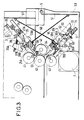
- the pocket folder shown is designated by the reference 1. It comprises two folding pockets 2 and 3 with which is associated a set 4 of folding rollers.
- the two pockets 2 and 3 are arranged along the branches of a truncated V on the assembly 4 of folding rollers then with four rollers.
- the two pockets 2 and 3 and the assembly 4 of folding rollers are mounted inside a chassis formed in two parts, one upper 5A and the other lower 5B.
- Pocket 2 is mounted in the upper part 5A and the pocket 3 in the lower part 5B.
- the two pockets 2 and 3 are similar to each other. Each of them forms a sort of flat cassette into which the document to be folded partially fits.
- Each of the pockets consists of a pair of plates coupled to each other, receiving between them the document to be folded. These plates are designated by the references 20 and 21 for the pocket 2 and by the references 30 and 31 for the pocket 3.
- the plates 20 and 21 are coupled to each other on a terminal hinge pin 22.
- the pocket 2 When the pocket 2 is mounted in the chassis one of its plates is fixed in the upper part 5A of the chassis, the on the other hand, another plate remains pivoting on the hinge axis 22.
- This hinge axis defines the bottom of the pocket opposite its access 23 for documents which is adjacent to all of the rollers.
- the pivoting plate is the plate 20 extending from the side of the lower part 5B of the chassis in which the pocket 2 concerned is not mounted; the fixed plate is plate 21.
- the pair of plates 30 and 31 for the pocket 3 is mounted in a similar manner to the pair of plates 20 and 21, but in the lower part 5B of the chassis.
- the plate 30 extending from the side of the upper part 5A of the chassis is pivotable about an axis 32 coupling the plates 30 and 31 at the end of the pocket 3 opposite its access to documents 33.
- the plate 31 is fixed in the lower part 5B of the chassis.
- the set 4 of folding rollers has its four rollers bearing the references 40 to 43.
- the roller 40 has the other three rollers 41, 42 and 43 which are tangent to it on its periphery.
- the access 23 of the pocket 2 is interposed between the peripheral rollers 41 and 42 and is opposite the roller 40.
- the access 33 of the pocket 3 is interposed between the peripheral rolls 42 and 43 and is also opposite the roller 40 .
- Two of these four rollers are mounted in the upper part 5A of the chassis, here the two rollers 40 and 41; the other two rollers 42 and 43 are mounted in the lower part 5B.
- a path 10 for the documents to be folded is provided in the upper part 5A of the chassis.
- An exit path 11 of folded documents is defined between the lower part 5B and the upper part 5A of the chassis.
- the document supply path 10 is supplied from a document input 12; this entry is equipped with a serving shelf transferring successive separate documents to be folded or in store and associated destacker also transferring successive separate documents to be folded.
- This feed path 10 comprises means 13 for driving the received documents, it guides them between the rollers 40 and 41.
- the outlet path 11 includes the rollers 40 and 43 which deliver the folded documents and drive means 14 folded documents up to an outlet 15 defined at the front of the folder, on the terminal part of the lower part 5B of the chassis.
- the drive means 13 and 14 on the tracks 10 and 11 are pairs of rollers, or the like, under pressure. They are mounted in the upper part 5A of the chassis for those relating to the path 10. They are mounted, like the rollers 40 and 43, opposite in the upper part 5A and the lower part 5B of the chassis for those relating to the exit path 11 which is defined between these two parts.
- the upper part 5A of the chassis is articulated on an end axis, noted 5, of the lower part 5B for its opening.
- This axis 5 is parallel to the articulation axes 22, 32 of the pivoting plates of the pockets. It extends substantially between these axes, opposite the outlet 15 on the folder.
- the upper part 5A of the chassis is also lockable on the lower part 5B of the chassis by any suitable means, not shown.
- FIG. 1 The folding machine according to the invention illustrated closed in FIG. 1 is on the other hand illustrated open in FIG. 2, in order to bring out its advantages directly.
- the opening of the folder is made by the pivoting according to arrow 5C of the upper part 5A of the frame around its axis 5.
- This opening of the folder gives direct access to the exit path 11 of folded documents, which is itself open along its length. It also gives very easy access to the supply path 10, via the open lower face of the upper part 5A of the chassis.
- the opening of the folder allows the opening of one and / or the other of the pockets to give free access to all the interior housing defined by each of them.
- the arrow 20C translates the pivoting of the pivoting plate 20 around the axis 22 for the opening of the pocket 2.
- the arrow 30C translates the same operation for the pocket 3.
- FIG. 3 it can be seen that the pivoting plate 20 and the fixed plate 21 of the pocket 2 are coupled to one another on the articulation axis 22 provided for the pivoting plate 20.
- the axis of articulation 22 is centered on the height of the pocket, at its rear end.
- Both of the plates 20 and 21 have fixing lugs on the axis 22, such as 24, protruding on their inner face and in the vicinity of their rear edge. These legs have their projecting part of semi-circular profile; they maintain the plates on the axis 22 and contribute to the slight separation of the plates from one another.
- the fixed plate 21 of the pocket 2 is also fixed using screws such as 25 on the upper part 5A of the chassis to avoid any possible movement of this plate around the axis 22.
- the pivoting plate 20 is it is urged elastically towards the plate 21, by a spring 26, fixed on the one hand on the edge of the plate 20 and on the other hand on the upper part 5A of the chassis.
- One of the two plates 20 and 21, here the plate 21, has in its end portion opposite the axis 22, a lateral heel 21A which ensures the desired spacing between the plates 20 and 21, against the action of the spring 26.
- a pair of legs with a U-shaped branch can ensure, at the same time, the fixing of the plate 21 on the upper part of the chassis and the non-abutment of the faces opposite the plates 20 and 21 against the action of the elastic means urging the pivoting plate against the fixed plate.
- the plates 20 and 21 each have in their middle portion a window 27A or 27B depending on the plate considered.
- a set of rollers 28A is mounted on the plate 20 in its window 27A and another set of rollers 28B is mounted on the plate 21 in its own window 27B.
- the rollers 28B carried by the fixed plate 21 are slightly projecting on the inner face of this plate; the rollers 28A are flush with the pocket on the inside of the pivoting plate.
- These rollers 28A and 28B correspond to be a vis-à-vis on the plates and come into contact against each other, under slight pressure inside the pocket 2. They ensure, when folding several documents together , a tightening without sliding of these documents against each other.
- This tightening is used to allow the retention of multiple documents to be folded together and in particular of small format documents to be folded with larger documents, and thus avoid causing possible additional jams.
- These projecting rollers inside the pocket 2 are advantageously closer to the access 23 than to the hinge pin 22 of the rear end.
- a pivoting finger 29 is mounted on the fixed plate 21, in an erasable obstacle by the simple advance of the documents to be folded into the pocket 2.
- the finger 29 extends, through the window 27B of the plate 21, or another individual window , as far as the corresponding window of the pivoting plate 20, when it is in obstacle inside the pocket. He fades into his home from the plate 21, as shown diagrammatically in dotted lines, when a document to be folded is present in the pocket.
- This finger 29 is coupled to a lever 29A which it actuates.
- the lever extends over the outside of the pocket 2. It serves as a document presence detector in the pocket 2. It is therefore associated with a jam detection circuit in the pocket 2, not shown, which comprises a pair of cells assigned to detecting the position of the lever and therefore of the pivoting finger 29, a time delay and a logic decision circuit.
- the time delay is triggered by the pair of cells as soon as finger 29 is deleted; it is chosen to translate the maximum time interval of presence in the pocket of a normally discharged document, which does not give rise to a jam.
- the return to obstacle of the pivoting finger cancels the triggering of the delay.
- the pocket 3 is similarly equipped. Its plates 30 and 31 have lugs 34 ensuring their maintenance on the hinge pin 32.
- the fixed plate 31 is held by means not shown on the lower part 5B of the chassis.
- a spring urges the pivoting plate 30 towards the fixed plate 31.
- a lateral heel 30A, here on the plate 30, or another means ensures with the lugs 34 the desired spacing of the plates 30 and 31.
- These plates have windows 37A, 37B in which rollers 38A, 38B are mounted in contact with one another in the pocket.
- the roller 38B is protruding in the pocket, the other 38A just flush with the plate 30.
- a pivoting finger 39 mounted on the fixed plate 31 forms an erasable obstable in the pocket 3.
- a lever 39A actuated by the finger 39 allows detection presence of document in pocket 3 and controls a jam detection circuit, not shown, for this pocket 3 similar to that assigned to pocket 2.
- each pocket can be equipped with an individual or common photoelectric detector 29 ′, 39 ′, as shown diagrammatically in FIG. 1.
- the emitter and detector cells of each individual detector 29 ′, 39 ′ can be mounted on the plates of each pocket, or on the outside of the plates of each pocket being coupled to one another, in the absence of a document in the pocket, through suitable windows in its plates.
- the transmitting cell and the receiving cell of the common detector can be mounted on the fixed plates 21, 31 of either of the pockets 2, 3; they are coupled through suitable windows of the pivoting plates 20 and 30 of the pockets 2, 3 when the folder is closed and in the absence of a document in one of the two pockets.
- At least one of the two plates of each pocket can be equipped with a projecting edge on its inner face, on each lateral side of the pocket, which laterally closes the pocket when the folder is closed.
- These edges can play the role of the aforementioned heels for the desired spacing between the fixed plate and the pivoting plate, or can come to project outwardly on the plate opposite that which carries them.
- a shutter 53 is mounted on the side of the access 23 of the pocket 2. It is pivotable between an open position, shown in dotted lines, and a closed position shown in solid lines. This flap, depending on its position, allows the pocket 2 of the folder to be used or not.
- a stop 62 is mounted in the pocket 3. It forms an obstacle inside the pocket 3, towards its end close to the hinge pin 32. It is carried by the fixed plate 31 of this pocket. This stop is adjustable relative to the access 33 of the pocket 3 according to the arrow 63 and / or is retractable on the fixed plate.
- each of the pockets can be equipped with a pivoting shutter for closing off its access, such as the shutter 53 and with a stop such as 62.
- An individual or common external control is coupled to the shutter 53 of the pocket 2 and at the stop 62 of the pocket 3 for putting the shutter in its desired position depending on whether or not it is desired to use the pocket 2 and putting the stop at its corresponding suitable position.
- the folder thus makes it possible to fold the documents it receives in three, by using its two pockets, or a folding in half of the documents, by using only one of its two pockets, in this case pocket 3 .
- FIG. 4 corresponds to FIG. 3 and shows the folder with the upper part 5A of its chassis open on the lower part 5B, by pivoting along the arrow 5C around the axis 5.
- the cables 50 and 60 fixed on the pivoting plates pockets 2 and 3 then caused the opening of the pockets with the opening of the folder according to arrow 5C.
- the arrow 20C translates the pivoting of the pivoting plate 20 around the axis 22 which has been carried out.
- An arrow 30C translates the pivoting of the pivoting plate 30 around the axis 32, for the pocket 3.
- the pivoting plate 30 has been truncated so as not to extend up to to the folding rollers 42 and 43.
- a small auxiliary plate 64 replaces the truncated end part of the pivoting plate 30.
- This auxiliary plate 64 is fixedly mounted in the lower part 5B of the chassis; it simply defines the access to the pocket 3, with the facing portion of the fixed plate 31.
- the pivoting plate 30, with a truncated end portion thus freely escapes the folding roller 42 when the folder is opened and the resulting opening of the pocket 3.
- the plates 20, 21 and 30, 31 have been made of sufficient thickness to allow the mounting of the elements which equip each of the pockets and which these plates carry.
- the end portions of the plates 20, 21 and 31 and of the counter plate 64 which define the accesses 23, 33 of the pockets, are made of less thickness so that their outer faces escape the folding rollers 41, 42 and 42, 43 and allow good interposition of accesses 23 and 33 of these pockets between these rollers.
- a motor 7 drives the folding rollers 40-43 and the rollers or rollers on the supply and exit paths 10 of the folder.
- This motor 7 is coupled to the roller 43 which itself drives by friction, or a coupling by toothed gears, the roller 40, when the folder is closed according to FIG. 3 and put into operation.
- This roller 40 in turn identically drives the rollers 41 and 42.
- the operation of the folder is not modified by the particular constitution of its set of rollers mounted partly in the upper part of the chassis and for the other part in the lower part of the chassis, nor by the particular constitution of its pockets.
- the rollers 40 and 41 drive the document to be folded and introduce it into the open pocket 2; the advance of the document into the pocket is blocked by the tabs 24 at the rear of the pocket or the internal stop that it may include, for the formation of a loop in front of the access 23; the taking of this loop between the rollers 40 and 42 gives rise to the first folding and ensures the introduction of the document into the pocket 3, with this first fold in head, while the document emerges from the pocket 2 and remains driven by the rollers 40, 41.
- the second fold is obtained in the same way and the document is discharged folded in three by rollers 40 and 43 on the exit path.
- the pivoting finger in each pocket disappears with the presence of the document at its level and puts itself in obstacle when the document is withdrawn at its level.
- the protruding rollers in the pocket upstream of the finger maintain a clamping of the documents in the pocket during their advance and their withdrawal from the pocket. Excessive holding in time of this pivoting finger in the erased position indicates jamming; it gives rise to the stop of the folder. The removal of such a jam is then carried out quickly and simply by opening the folder.
Landscapes
- Folding Of Thin Sheet-Like Materials, Special Discharging Devices, And Others (AREA)
- Making Paper Articles (AREA)
Claims (10)
- Aus zwei Teilen bestehende Falzmaschine mit Taschen, wobei das Unterteil (5B) und das Oberteil (5A) gelenkig zum Öffnen der Maschine miteinander verbunden sind, wobei ein Eingang (12) für zu faltende Blätter sich im Oberteil und ein Ausgang (15) für gefaltete Blätter sich im Unterteil befindet,- mit einer Gruppe (4) von Faltrollen, die die zu faltenden Blätter vom Eingang (12) zugeführt erhalten und sie gefaltet an einen Ausgangsschacht (11) liefern, der zum Ausgang (15) führt,- mit einer ersten Tasche (2) im Oberteil und einer zweiten Tasche (3) im Unterteil, die je einen Zugang (23, 33) für die Blätter in der Nähe der Gruppe (4) von Rollen besitzen,dadurch gekennzeichnet, daß die Falzmaschine aus einem zweiteiligen Chassis besteht, das ein Oberteil (5A) und ein Unterteil (5B) der Falzmaschine definiert, und daß die Gruppe (4) von Rollen zum Teil (40, 41) im Oberteil (5A) des Chassis und zum anderen Teil (42, 43) im Unterteil (5B) des Chassis montiert ist, wobei der Ausgangsschacht (11) für gefaltete Blätter unmittelbar zwischen dem Unterteil (5B) und dem Oberteil (5A) des Chassis ausgebildet ist und wobei beim Öffnen des Chassis die Gruppe (4) von Rollen sich zerlegt und öffnet, der Ausgangsschacht (11) sich öffnet und die Taschen (2, 3) sich ebenfalls öffnen.
- Falzmaschine mit Taschen nach Anspruch 1, in der die erste und die zweite Tasche je durch eine feste Wand (21, 31) und eine dieser gegenüberliegende schwenkbare Wand (20, 30) definiert sind, so daß die Taschen sich beim Öffnen des Oberteils des Falzmaschine öffnen, dadurch gekennzeichnet, daß die erste Tasche (2) und die zweite Tasche (3), und zwar in gleicher Weise und unabhängig von dem Chassis, je ein Paar von Platten (20, 21; 30, 31) aufweisen, die aneinander über eine endseitige Schwenkachse (22, 32) am dem Zugang entgegengesetzten Ende der Tasche gekoppelt sind, und daß weiter für jede Tasche erste Mittel (25) zur Befestigung einer der Platten, nämlich der festen Platte (21, 31), auf dem Chassis, zweite elastische Mittel (26), die die andere, nämlich die die schwenkbare Platte (20, 30) bildende Platte, elastisch gegen die feste Wand drücken, und dritte Separatormittel (21A, 30A; 24, 34) vorgesehen sind, die dafür sorgen, daß die beiden einander gegenüberliegenden Seiten der Paare von Platten nicht aufeinanderkleben.
- Falzmaschine mit Taschen nach Anspruch 2, dadurch gekennzeichnet, daß sie außerdem mindestens eine erste Rolle (28B, 38B) aufweist, die auf einer der Platten jeder der Taschen montiert ist und gegen die andere Platte dieser Tasche vorsteht.
- Falzmaschine mit Taschen nach Anspruch 3, dadurch gekennzeichnet, daß sie außerdem mindestens eine zweite Rolle (28A, 38A) aufweist, die auf der anderen Platte jeder Tasche montiert ist und mit deren Innenseite fluchtet, wobei die erste, vorstehende Rolle (28B, 38B) auf ihr aufliegt.
- Falzmaschine mit Tasche nach einem der Ansprüche 2 bis 4, dadurch gekennzeichnet, daß die Separatormittel Füße (24, 34) aufweisen, die auf den einander gegenüberstehenden Seiten der Platten jeder Tasche vorstehen und die Platten auf der endseitigen Schwenkachse (22, 32) halten.
- Falzmaschine mit Taschen nach Anspruch 5, dadurch gekennzeichnet, daß die Separatormittel außerdem mindestens einen seitlichen Absatz (21A, 30A) auf einer ihrer Platten aufweisen, der zur anderen Platte hin vorsteht.
- Falzmaschine mit Taschen nach einem der Ansprüche 1 bis 6, dadurch gekennzeichnet, daß die feste Platte (21, 31) jeder Tasche einen schwenkbaren Finger (29, 39) trägt, der als durch das Dokument im Inneren der Tasche entfernbares Hindernis montiert ist und an ein außerhalb der Tasche liegendes Detektorelement (29A) gekoppelt ist, das das Vorliegen eines Dokuments in der Tasche erfaßt.
- Falzmaschine mit Taschen nach einem der Ansprüche 2 bis 6, dadurch gekennzeichnet, daß sie einen lichtelektrischen Detektor (29', 39') zur Erfassung des Vorliegens eines Dokuments in den Taschen enthält.
- Falzmaschine mit Taschen nach Anspruch 8, dadurch gekennzeichnet, daß der lichtelektrische Detektor (29', 39') für die erste Tasche und die zweite Tasche gemeinsam vorgesehen ist und eine Sendezelle und eine Detektorzelle besitzt, die miteinander durch die Taschen (2, 3) hindurch gekoppelt sind, wenn kein Dokument in einer beliebigen der Taschen vorliegt.
- Falzmaschine mit Taschen nach einem der Ansprüche 2 bis 9, bei der die schwenkbare Wand (20, 30) jeder der Taschen (2, 3) diejenige der Platten ist, die gegenüber dem Chassisteil liegt, das die betrachtete Tasche nicht trägt, dadurch gekennzeichnet, daß sie ein Seil (50, 60) zum Öffnen jeder Tasche (2, 3) aufweist, das einerseits an der schwenkbaren Wand (20, 30) der Tasche und andererseits an einem in demjenigen Teil des Chassis montierten Träger (51, 52) befestigt ist, der die betrachtete Tasche nicht trägt, wobei das Seil ein Öffnen der Tasche entgegen der Wirkung der elastischen Mittel (26) bewirkt, die mit der schwenkbaren Platte dieser Tasche gekoppelt sind, wenn das Oberteil (5A) vom Unterteil (5B) hochgeschwenkt wird.
Applications Claiming Priority (2)
| Application Number | Priority Date | Filing Date | Title |
|---|---|---|---|
| FR8810119 | 1988-07-27 | ||
| FR8810119A FR2634747B1 (fr) | 1988-07-27 | 1988-07-27 | Plieuse a poches |
Publications (2)
| Publication Number | Publication Date |
|---|---|
| EP0352694A1 EP0352694A1 (de) | 1990-01-31 |
| EP0352694B1 true EP0352694B1 (de) | 1993-03-24 |
Family
ID=9368826
Family Applications (1)
| Application Number | Title | Priority Date | Filing Date |
|---|---|---|---|
| EP89113564A Expired - Lifetime EP0352694B1 (de) | 1988-07-27 | 1989-07-24 | Stauchfalzmaschine |
Country Status (7)
| Country | Link |
|---|---|
| US (1) | US5000432A (de) |
| EP (1) | EP0352694B1 (de) |
| AU (1) | AU611819B2 (de) |
| CA (1) | CA1312099C (de) |
| DE (1) | DE68905547T2 (de) |
| ES (1) | ES2040941T3 (de) |
| FR (1) | FR2634747B1 (de) |
Cited By (4)
| Publication number | Priority date | Publication date | Assignee | Title |
|---|---|---|---|---|
| DE102023126171A1 (de) | 2022-10-04 | 2024-04-04 | Elmos Semiconductor Se | QRNG mit PRNG Nutzung und vertikaler Entropiequelle |
| DE102024127097A1 (de) | 2023-09-20 | 2025-03-20 | Elmos Semiconductor Se | Netzwerkknoten für ein verteiltes Netzwerk mit dezentraler Zufallszahlengenerierung zur Sicherstellung von Sicherheit und Robustheit |
| DE102024127111A1 (de) | 2023-09-20 | 2025-03-20 | Elmos Semiconductor Se | Verteiltes Steckverbindernetzwerk mit dezentraler Zufallszahlengenerierung zur Sicherstellung von Sicherheit und Robustheit |
| DE102024109016A1 (de) | 2023-09-20 | 2025-03-20 | Elmos Semiconductor Se | Hybrid Integrierter Quanten-Zufallszahlengenerator |
Families Citing this family (16)
| Publication number | Priority date | Publication date | Assignee | Title |
|---|---|---|---|---|
| DD297383A5 (de) * | 1990-08-31 | 1992-01-09 | �������@������������@��k�� | Falzmaschine |
| FR2668459B1 (fr) * | 1990-10-31 | 1992-12-24 | Alcatel Satmam | Plieuse a poches, a trois parties. |
| GB9101377D0 (en) * | 1991-01-22 | 1991-03-06 | Watkiss Automation Ltd | Stitcher/folder apparatus |
| US5297783A (en) * | 1991-11-12 | 1994-03-29 | Pitney Bowes Inc. | Apparatus and system for handling cut sheets and web forms to form discrete batches |
| US5234399A (en) * | 1991-12-17 | 1993-08-10 | Pitney Bowes Inc. | Buckle chute jam access means |
| US5391138A (en) * | 1993-03-24 | 1995-02-21 | The Hedman Company | Sheet feeding system for a sheet folding apparatus |
| FR2724642B1 (fr) * | 1994-09-15 | 1996-12-13 | Danel Ferry | Plieuse pour la fabrication d'enveloppes a deux plis roules avec inserts |
| USD368724S (en) | 1995-05-30 | 1996-04-09 | Daniel Vaccaro | Paper folder |
| EP0860393B1 (de) * | 1997-02-25 | 1998-12-23 | Cratech GmbH | Maschine zum Falten von blattförmigen Gegenständen |
| EP1295982A1 (de) * | 2001-09-20 | 2003-03-26 | Jensen AG Burgdorf | Falteinrichtung zum Falten von Wäschestücken |
| DE202004005361U1 (de) * | 2004-04-05 | 2004-06-03 | Maschinenbau Oppenweiler Binder Gmbh & Co. Kg | Kreuzbruchmodul mit aufklappbarem Oberteil |
| DE202005005532U1 (de) * | 2005-04-07 | 2005-06-16 | Maschinenbau Oppenweiler Binder Gmbh & Co. Kg | Taschenfalzmaschine mit Falztaschenkassette |
| DE102006018768B4 (de) | 2006-04-20 | 2008-02-07 | Kugler-Womako Gmbh | Vorrichtung zum Transport bogenförmiger flacher Gegenstände |
| USD551265S1 (en) | 2006-10-12 | 2007-09-18 | Garland Brinson | Paper folder |
| JP5002529B2 (ja) * | 2008-05-22 | 2012-08-15 | デュプロ精工株式会社 | 用紙折り機構及び用紙折り装置 |
| DE102012025013B4 (de) | 2012-12-20 | 2015-03-05 | Böwe Systec Gmbh | Klappfalzwerk und Verfahren zum Falzen von Flachgut |
Citations (1)
| Publication number | Priority date | Publication date | Assignee | Title |
|---|---|---|---|---|
| US4619101A (en) * | 1985-12-16 | 1986-10-28 | Pitney Bowes Inc. | Sheet folding inserting machine |
Family Cites Families (4)
| Publication number | Priority date | Publication date | Assignee | Title |
|---|---|---|---|---|
| US3901501A (en) * | 1969-11-22 | 1975-08-26 | Oppenweiler Binder & Co Maschb | Device for making a thrice parallel folded sheet in which the open bent covers are directed towards the middle |
| DE3447301A1 (de) * | 1984-02-17 | 1985-09-05 | Mathias Bäuerle GmbH, 7742 St Georgen | Stauchfalzmaschine |
| DE3412606A1 (de) * | 1984-04-04 | 1985-10-24 | Mathias Bäuerle GmbH, 7742 ST. Georgen | Stauchfalzmaschine mit schutzgehaeuse |
| JPS612669A (ja) * | 1984-06-15 | 1986-01-08 | Canon Inc | シ−ト折り装置 |
-
1988
- 1988-07-27 FR FR8810119A patent/FR2634747B1/fr not_active Expired - Lifetime
-
1989
- 1989-07-17 US US07/380,342 patent/US5000432A/en not_active Expired - Lifetime
- 1989-07-21 AU AU38871/89A patent/AU611819B2/en not_active Ceased
- 1989-07-24 DE DE8989113564T patent/DE68905547T2/de not_active Expired - Fee Related
- 1989-07-24 ES ES198989113564T patent/ES2040941T3/es not_active Expired - Lifetime
- 1989-07-24 CA CA000606472A patent/CA1312099C/fr not_active Expired - Lifetime
- 1989-07-24 EP EP89113564A patent/EP0352694B1/de not_active Expired - Lifetime
Patent Citations (1)
| Publication number | Priority date | Publication date | Assignee | Title |
|---|---|---|---|---|
| US4619101A (en) * | 1985-12-16 | 1986-10-28 | Pitney Bowes Inc. | Sheet folding inserting machine |
Cited By (12)
| Publication number | Priority date | Publication date | Assignee | Title |
|---|---|---|---|---|
| DE102023126171A1 (de) | 2022-10-04 | 2024-04-04 | Elmos Semiconductor Se | QRNG mit PRNG Nutzung und vertikaler Entropiequelle |
| DE102023126170A1 (de) | 2022-10-04 | 2024-04-04 | Elmos Semiconductor Se | QRNG mit PRNG Nutzung und vertikaler Entropiequelle |
| DE102023126168A1 (de) | 2022-10-04 | 2024-04-04 | Elmos Semiconductor Se | Integrierter Quanten-Zufallszahlengenerator |
| WO2024074170A1 (de) | 2022-10-04 | 2024-04-11 | Elmos Semiconductor Se | Qrng mit prng nutzung und vertikaler entropiequelle |
| DE102024127097A1 (de) | 2023-09-20 | 2025-03-20 | Elmos Semiconductor Se | Netzwerkknoten für ein verteiltes Netzwerk mit dezentraler Zufallszahlengenerierung zur Sicherstellung von Sicherheit und Robustheit |
| DE102024127111A1 (de) | 2023-09-20 | 2025-03-20 | Elmos Semiconductor Se | Verteiltes Steckverbindernetzwerk mit dezentraler Zufallszahlengenerierung zur Sicherstellung von Sicherheit und Robustheit |
| DE102024109016A1 (de) | 2023-09-20 | 2025-03-20 | Elmos Semiconductor Se | Hybrid Integrierter Quanten-Zufallszahlengenerator |
| DE102024127105A1 (de) | 2023-09-20 | 2025-03-20 | Elmos Semiconductor Se | Gegen Cyber-Angriffe quantenzufallsbit-geschützter Schwarm individualisierter, steuerbarer Objekte und zugehörige Objekte |
| DE102024127101A1 (de) | 2023-09-20 | 2025-03-20 | Elmos Semiconductor Se | Quantenzufallszahlengenerator mit Krypto-Engine |
| DE102024127099A1 (de) | 2023-09-20 | 2025-03-20 | Elmos Semiconductor Se | Individualisierte Miniatur-Roboter |
| DE102024127103A1 (de) | 2023-09-20 | 2025-03-20 | Elmos Semiconductor Se | Verfahren zur Herstellung eines mikroelektronischen Schaltkreises mit einem Quantenzufallszahlengenerator mit vertikaler Entropiequelle |
| DE102024127095A1 (de) | 2023-09-20 | 2025-03-20 | Elmos Semiconductor Se | Verteiltes Netzwerk mit dezentraler Zufallszahlengenerierung zur Sicherstellung von Sicherheit und Robustheit |
Also Published As
| Publication number | Publication date |
|---|---|
| FR2634747A1 (fr) | 1990-02-02 |
| AU3887189A (en) | 1990-02-01 |
| FR2634747B1 (fr) | 1990-09-14 |
| EP0352694A1 (de) | 1990-01-31 |
| AU611819B2 (en) | 1991-06-20 |
| DE68905547D1 (de) | 1993-04-29 |
| CA1312099C (fr) | 1992-12-29 |
| ES2040941T3 (es) | 1993-11-01 |
| US5000432A (en) | 1991-03-19 |
| DE68905547T2 (de) | 1993-07-01 |
Similar Documents
| Publication | Publication Date | Title |
|---|---|---|
| EP0352694A1 (de) | Stauchfalzmaschine | |
| EP0352692B1 (de) | Integrierte Büromaschine zum Falten und Kuvertieren von Poststücken | |
| LU83199A1 (fr) | Distributeur de produits en feuilles | |
| CH654682A5 (fr) | Appareil pour recuperer des billets non ramasses dans un poste distributeur d'une machine de banque automatique. | |
| EP0362056A1 (de) | Tragbarer Registerkasten | |
| EP0352686B1 (de) | Vorrichtung zum Öffnen und Füllen von Briefumschlägen | |
| EP0326056B1 (de) | Universelle Faltvorrichtung | |
| EP0485797B1 (de) | Dreiteilige Staufalzvorrichtung | |
| FR2611058A1 (fr) | Dispositif de chargement et de dechargement de cassettes de films radiographiques | |
| FR2726223A1 (fr) | Cassette de chargement de feuilles comportant une plaque elevatrice et un couvercle ayant une zone de poussee pour abaisser la plaque elevatrice | |
| EP0317929A1 (de) | Vorrichtung zum Füllen von Briefumschlägen | |
| CA2651600A1 (fr) | Dispositif perfectionne de selection d'articles de courrier | |
| EP1074393B1 (de) | Papierstaubeseitigungsvorrichtung für einen Zuführer einer Frankiermaschine | |
| EP1854648B1 (de) | Lamellenrollläden für Fahrzeuge | |
| CA1272991A (fr) | Dispositif d'insertion de liasse dans une enveloppe | |
| FR2726222A1 (fr) | Cassette de chargement de feuilles comportant un receptacle et un couvercle ayant des moyens de prevention empechant le passage de feuilles entre le couvercle et le receptacle | |
| EP0786359A1 (de) | Dokumentenführungsvorrichtung für eine Falz- und/oder Kuvertiermaschine | |
| EP0247523A1 (de) | Vorrichtung zum Öffnen von Briefumschlägen | |
| WO2023131672A1 (fr) | Boite de transfert d'articles dans un carton | |
| EP0317928B1 (de) | Vorrichtung zum Auswerfen von gefüllten Briefumschlägen | |
| EP0374826A1 (de) | Entstapler für flache Gegenstände | |
| FR2641770A1 (fr) | Appareil de manutention pour agrafage de piles de feuilles | |
| BE1009854A3 (fr) | Distributeur d'objets plats et flexibles. | |
| FR2659097A2 (fr) | Dispositif gravillonneur. | |
| CH629017A5 (fr) | Machine pour le comptage de feuilles de papier. |
Legal Events
| Date | Code | Title | Description |
|---|---|---|---|
| PUAI | Public reference made under article 153(3) epc to a published international application that has entered the european phase |
Free format text: ORIGINAL CODE: 0009012 |
|
| AK | Designated contracting states |
Kind code of ref document: A1 Designated state(s): BE DE ES FR GB IT NL |
|
| 17P | Request for examination filed |
Effective date: 19900730 |
|
| 17Q | First examination report despatched |
Effective date: 19920408 |
|
| GRAA | (expected) grant |
Free format text: ORIGINAL CODE: 0009210 |
|
| AK | Designated contracting states |
Kind code of ref document: B1 Designated state(s): BE DE ES FR GB IT NL |
|
| RAP2 | Party data changed (patent owner data changed or rights of a patent transferred) |
Owner name: NEOPOST INDUSTRIE |
|
| REF | Corresponds to: |
Ref document number: 68905547 Country of ref document: DE Date of ref document: 19930429 |
|
| GBT | Gb: translation of ep patent filed (gb section 77(6)(a)/1977) |
Effective date: 19930402 |
|
| ITF | It: translation for a ep patent filed | ||
| REG | Reference to a national code |
Ref country code: ES Ref legal event code: FG2A Ref document number: 2040941 Country of ref document: ES Kind code of ref document: T3 |
|
| PLBE | No opposition filed within time limit |
Free format text: ORIGINAL CODE: 0009261 |
|
| STAA | Information on the status of an ep patent application or granted ep patent |
Free format text: STATUS: NO OPPOSITION FILED WITHIN TIME LIMIT |
|
| 26N | No opposition filed | ||
| REG | Reference to a national code |
Ref country code: GB Ref legal event code: IF02 |
|
| PGFP | Annual fee paid to national office [announced via postgrant information from national office to epo] |
Ref country code: DE Payment date: 20050713 Year of fee payment: 17 |
|
| PGFP | Annual fee paid to national office [announced via postgrant information from national office to epo] |
Ref country code: FR Payment date: 20050715 Year of fee payment: 17 |
|
| PGFP | Annual fee paid to national office [announced via postgrant information from national office to epo] |
Ref country code: ES Payment date: 20050718 Year of fee payment: 17 |
|
| PGFP | Annual fee paid to national office [announced via postgrant information from national office to epo] |
Ref country code: BE Payment date: 20050719 Year of fee payment: 17 Ref country code: NL Payment date: 20050719 Year of fee payment: 17 |
|
| PGFP | Annual fee paid to national office [announced via postgrant information from national office to epo] |
Ref country code: GB Payment date: 20050727 Year of fee payment: 17 |
|
| PG25 | Lapsed in a contracting state [announced via postgrant information from national office to epo] |
Ref country code: GB Free format text: LAPSE BECAUSE OF NON-PAYMENT OF DUE FEES Effective date: 20060724 |
|
| PG25 | Lapsed in a contracting state [announced via postgrant information from national office to epo] |
Ref country code: BE Free format text: LAPSE BECAUSE OF NON-PAYMENT OF DUE FEES Effective date: 20060731 |
|
| PGFP | Annual fee paid to national office [announced via postgrant information from national office to epo] |
Ref country code: IT Payment date: 20060731 Year of fee payment: 18 |
|
| PG25 | Lapsed in a contracting state [announced via postgrant information from national office to epo] |
Ref country code: NL Free format text: LAPSE BECAUSE OF NON-PAYMENT OF DUE FEES Effective date: 20070201 Ref country code: DE Free format text: LAPSE BECAUSE OF NON-PAYMENT OF DUE FEES Effective date: 20070201 |
|
| GBPC | Gb: european patent ceased through non-payment of renewal fee |
Effective date: 20060724 |
|
| NLV4 | Nl: lapsed or anulled due to non-payment of the annual fee |
Effective date: 20070201 |
|
| REG | Reference to a national code |
Ref country code: FR Ref legal event code: ST Effective date: 20070330 |
|
| REG | Reference to a national code |
Ref country code: ES Ref legal event code: FD2A Effective date: 20060725 |
|
| BERE | Be: lapsed |
Owner name: *ALCATEL SATMAM Effective date: 20060731 |
|
| PG25 | Lapsed in a contracting state [announced via postgrant information from national office to epo] |
Ref country code: ES Free format text: LAPSE BECAUSE OF NON-PAYMENT OF DUE FEES Effective date: 20060725 |
|
| PG25 | Lapsed in a contracting state [announced via postgrant information from national office to epo] |
Ref country code: FR Free format text: LAPSE BECAUSE OF NON-PAYMENT OF DUE FEES Effective date: 20060731 |
|
| PG25 | Lapsed in a contracting state [announced via postgrant information from national office to epo] |
Ref country code: IT Free format text: LAPSE BECAUSE OF NON-PAYMENT OF DUE FEES Effective date: 20070724 |