EP0352751A2 - Optische Wellenlängenkonverter-Einrichtung und optisches Wellenlängenkonverter-Modul - Google Patents
Optische Wellenlängenkonverter-Einrichtung und optisches Wellenlängenkonverter-Modul Download PDFInfo
- Publication number
- EP0352751A2 EP0352751A2 EP89113715A EP89113715A EP0352751A2 EP 0352751 A2 EP0352751 A2 EP 0352751A2 EP 89113715 A EP89113715 A EP 89113715A EP 89113715 A EP89113715 A EP 89113715A EP 0352751 A2 EP0352751 A2 EP 0352751A2
- Authority
- EP
- European Patent Office
- Prior art keywords
- cladding
- optical
- wavelength converter
- exit end
- optical wavelength
- Prior art date
- Legal status (The legal status is an assumption and is not a legal conclusion. Google has not performed a legal analysis and makes no representation as to the accuracy of the status listed.)
- Granted
Links
Images





Classifications
-
- G—PHYSICS
- G02—OPTICS
- G02B—OPTICAL ELEMENTS, SYSTEMS OR APPARATUS
- G02B6/00—Light guides; Structural details of arrangements comprising light guides and other optical elements, e.g. couplings
- G02B6/02—Optical fibres with cladding with or without a coating
- G02B6/02052—Optical fibres with cladding with or without a coating comprising optical elements other than gratings, e.g. filters
-
- G—PHYSICS
- G02—OPTICS
- G02B—OPTICAL ELEMENTS, SYSTEMS OR APPARATUS
- G02B6/00—Light guides; Structural details of arrangements comprising light guides and other optical elements, e.g. couplings
- G02B6/24—Coupling light guides
- G02B6/26—Optical coupling means
- G02B6/34—Optical coupling means utilising prism or grating
-
- G—PHYSICS
- G02—OPTICS
- G02B—OPTICAL ELEMENTS, SYSTEMS OR APPARATUS
- G02B6/00—Light guides; Structural details of arrangements comprising light guides and other optical elements, e.g. couplings
- G02B6/24—Coupling light guides
- G02B6/42—Coupling light guides with opto-electronic elements
- G02B6/4201—Packages, e.g. shape, construction, internal or external details
- G02B6/4202—Packages, e.g. shape, construction, internal or external details for coupling an active element with fibres without intermediate optical elements, e.g. fibres with plane ends, fibres with shaped ends, bundles
- G02B6/4203—Optical features
-
- G—PHYSICS
- G02—OPTICS
- G02F—OPTICAL DEVICES OR ARRANGEMENTS FOR THE CONTROL OF LIGHT BY MODIFICATION OF THE OPTICAL PROPERTIES OF THE MEDIA OF THE ELEMENTS INVOLVED THEREIN; NON-LINEAR OPTICS; FREQUENCY-CHANGING OF LIGHT; OPTICAL LOGIC ELEMENTS; OPTICAL ANALOGUE/DIGITAL CONVERTERS
- G02F1/00—Devices or arrangements for the control of the intensity, colour, phase, polarisation or direction of light arriving from an independent light source, e.g. switching, gating or modulating; Non-linear optics
- G02F1/35—Non-linear optics
- G02F1/37—Non-linear optics for second-harmonic generation
- G02F1/377—Non-linear optics for second-harmonic generation in an optical waveguide structure
- G02F1/383—Non-linear optics for second-harmonic generation in an optical waveguide structure of the optical fibre type
Definitions
- the present invention relates to an optical wavelength converter device, which converts a fundamental wave into a second harmonic, having a wavelength which is 1/2 of that of the fundamental wave; to a fiber-type optical wavelength converter device which converts a fundamental wave into a third harmonic; to a fiber-type optical wavelength converter device which converts fundamental waves having two different wavelengths into a wave having a frequency equal to the sum of or the difference between the fundamental waves; and to an optical wavelength converter module which employs such an optical wavelength converter device. More particularly, it relates to an optical wavelength converter device and an optical wavelength converter module, both of which can convert the conical wavefront of a wavelength-converted wave into a plane or spherical wavefront.
- the optical wavelength converter device of this type is in the form of an optical fiber comprising a core made of nonlinear optical material and surrounded by a cladding.
- An example of such an optical fiber is shown in the vol. 3, No. 2, pages 28 - 32, bulletin of the microoptics research group of a gathering of the Applied Physics Society.
- Recently, many efforts are directed to the study of the fiber type optical wavelength converter device since it can easily gain phase matching between a guided mode in which a fundamental is guided through the core and a radiated mode in which a second harmonic is radiated into the cladding (the so-called Cherenkov radiation).
- the wavelength-converted wave produced by any of the above optical wavelength converter devices is emitted from the output end of the cladding and has various applications. In many of the applications, the wavelength-converted wave is converged into a small spot. For example, the wavelength-converted wave is focused into a very small spot for higher recording density when a wavelength-converted wave is used optically to record information signals.
- the wavelength-converted wave emitted from the fiber Cherenkov type optical wavelength converter device cannot converge into a small spot even if the emitted wave is passed through a general spherical lens.
- the principles of the present invention are based on the finding that a wavelength-converted wave (which is emitted at a certain phase matching angle and in phase with a fundamental wave) radiated into the cladding of a fiber Cherenkov type optical wavelength converter device has a conical wavefront.
- an optical wavelength converter device comprises a fiber Cherenkov type optical wavelength converter device which includes a cladding having an exit end for emitting a wavelength-converted wave, the exit end of the cladding being conical so that if converts the conical wavefront of the wavelength-converted wave into a plane wavefront.
- Japanese Unexamined Patent Publication No. 63(1988)-15235 discloses a fiber type optical wavelength converter device which has a cladding that is progressively tapered toward its exit end. However, the wavelength-converted wave is not emitted from the tapered portion of the cladding, but from a small inner cladding end perpendicular to the axis of the fiber. Since the angle of the tapered surface of the cladding is not selected on the phase matching angle, the disclosed fiber type optical wavelength converter device is different from the optical wavelength converter device according to the present invention.
- Another optical wavelength converter device comprises a fiber Cherenkov type optical wavelength converter device which includes a cladding with an exit end for emitting a wavelength-converted wave.
- the exit end has a grating composed of equally spaced concentric patterns which convert the conical wavefront of the wavelength-converted wave into a plane wavefront.
- an optical wavelength converter module comprising an optical wavelength converter device, of the type described above, and an optical device disposed in a position to receive a wavelength-converted wave emitted from the exit end of the cladding of the optical wavelength converter device, which converts the conical wavefront of the received wavelength-converted wave into a plane wavefront.
- the optical device may for example be a lens either having a conical entrance surface and/or a conical exit surface, a graded-index lens which is functionally equivalent to the above lens, or a grating having equally spaced concentric patterns.
- the optical device may be spaced from, or held intimately against, the exit end of the cladding.
- the wavelength-converted wave can converge into a small spot when passed through an ordinary spherical lens.
- still another optical wavelength converter device comprises a fiber Cherenkov type optical wavelength converter device which includes a cladding having an exit end for emitting a wavelength-converted wave, and the exit end of the cladding having an aspherical lens surface for converting the conical wavefront of the wavelength-converted wave into a spherical wavefront.
- Yet another optical wavelength converter device comprises also a fiber Cherenkov type optical wavelength converter device including a cladding which has an exit end for emitting a wavelength-converted wave, the exit end having a grating composed of concentric patterns for converting the conical wavefront of the wavelength-converted wave into a spherical wavefront.
- the present invention further provides an optical wavelength converter module comprising an optical wavelength converter device of the type described above and an optical device disposed in a position to receive the wavelength-converted wave emitted from the exit end of the cladding of the optical wavelength converter; this converts the conical wavefront of the received wavelength-converted wave into a spherical wavefront.
- the optical device may for example be a lens having entrance and exit surfaces thereof, being conical and spherical or a grating having concentric patterns which functions equivalently to the above lens.
- the optical device may be spaced from, or held intimately against, the exit end of the cladding.
- the wavelength-converted wave can be converged into a small spot. Even if the conical wavefront of the wavelength-converted wave has been converted into a divergent spherical wavefront, the wavelength-converted wave can be converged into a small spot by passing it through an ordinary spherical lens.
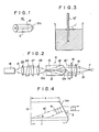
- FIGS 1 and 2 show an optical wavelength converter device 10 according to the first embodiment of the present invention.
- the optical wavelength converter device 10 comprises an optical fiber including a core 11, which is made of a nonlinear optical material and filled into the hollow space defined centrally in the cladding 12.
- the nonlinear optical material of the core 11 is preferably an organic nonlinear optical material having a high wavelength conversion efficiency.
- the core 11 is made of 3,5-dimethyl-1-(4-nitrophenyl)pyrazole (hereinafter referred to as "PRA").
- the core 11 is made of PRA and the cladding 12 is made of SFS3 glass.
- a hollow glass fiber 12′ which will serve as the cladding 12 is provided, the hollow glass fiber 12′ having an outside diameter of about 3mm and the hollow space therein having a diameter of about 2 ⁇ m, for example.
- PRA is kept as a molten solution 11′ in a furnace, and one end of the glass fiber 12′ is immersed in the molten solution 11′. The molten solution 11′ of PRA then enters the hollow space in the glass fiber 12′ due to capillarity.
- the molten solution 11′ is kept at a temperature slightly higher than the melting point of PRA (102°C) in order to prevent the PRA from being decomposed. Thereafter, the glass fiber 12′ is quickly cooled, causing the PRA in the hollow space to be polycrystallized.
- the glass fiber 12′ is gradually pulled from the furnace, which is kept at a temperature higher than the melting point of PRA (e.g. 102.5°C), into the outer space, which is kept at a temperature lower than that melting point, thereby causing the molten PRA to be monocrystallized continuously at the point where it is withdrawn from the furnace.
- the core 11 thus prepared is of highly long monocrystalline form with a uniform crystal orientation.
- the optical wavelength converter device 10 is thereby made sufficiently long.
- the opposite ends of the glass fiber 12′ are cut off at suitable points.
- One end 10a ( Figure 2) of the glass fiber, which is to serve as an entrance for receiving the light beam, is cut perpendicularly to the axis of the glass fiber.
- the other cladding end 12a of the glass fiber is finished to a conical shape by a known grinding process. In this manner, the optical wavelength converter device 10, shown in Figures 1 and 2, is produced. The configuration of the cladding end 12a will be described later on.
- the optical wavelength converter device 10 is used as shown in Figure 2.
- a semiconductor laser 16 capable of emitting a laser beam 15 (having a wavelength of 870nm, for example), is employed as the fundamental wave generating means.
- the laser beam (fundamental wave) 15 emitted as a divergent beam from the semiconductor laser 16 is converted by a collimator lens 25 to a parallel beam whose cross section is then shaped into a circular shape by beam shaper prisms 26, 27.
- the laser beam 15 is then converged by an objective lens 28 and applied to the entrance end 10a (the end of the core 11) of the optical wavelength converter device 10.
- the laser beam 15 now enters the core 11.
- the laser beam or fundamental wave 15 is then converted by the PRA of the core 11 into a second harmonic 15′ whose wavelength is 1/2 of the wavelength of the fundamental wave 15.
- the second harmonic 15′ is radiated into the cladding 12 and travels through the device 10 toward the opposite exit end thereof.
- Phase matching is achieved between a guided mode, in which the fundamental wave 15 is guided through the core 11, and a radiated mode, in which the second harmonic 15′ is radiated into the cladding 12 (Cherenkov radiation).
- the second harmonic 15′ is emitted out of the device 10 from the end 12a of the cladding 12.
- the fundamental wave 15, which has been guided through the core 11, is emitted from the end 11a of the core 11.
- a light beam 15 ⁇ , containing the second harmonic 15′, and the fundamental wave 15 then goes through a filter 18 which passes only the second harmonic 15′. Therefore, only the second harmonic 15′ is extracted by the filter 18.
- the second harmonic 15′ then passes through a condenser lens 19 in the form of a general spherical lens by which it is converged into a small beam spot P.
- Figure 2 does not show any device which utilizes the second harmonic 15′. However, such a device usually utilizes the focused spot of the second harmonic 15′.
- the cladding 12 is thick enough for the second harmonic 15′ radiated into the cladding 12 at a phase matching angle ⁇ to be emitted out of the device 10 directly from the cladding end 12a without being totally reflected by the outer surface of the cladding 12.
- the diameter D of the cladding 12 should be selected to meet the condition: D > 2L ⁇ tan ⁇ + d (1) where d is the diameter of the core 11 and L is the length of the outer peripheral surface of the cladding 12.
- the wavefront of the second harmonic 15′ traveling through the cladding 12 is oriented as indicated by the arrows W in Figure 4 in one plane including the core axis. Therefore, the wavefront is of a conical shape as a whole.
- the refractive index of the cladding 12 is indicated by n C
- the refractive index of a medium (usually air) around the device 10 by n A
- the angle of incidence of the second harmonic 15′ to the cladding end 12a by ⁇ the angle at which the cladding end 12a is inclined to a plane normal to the core axis by ⁇ .
- n C sin ⁇ n A sin ⁇ the wavefront of the second harmonic 15′ emitted out of the cladding 12 will become a plane wavefront.
- the optical wavelength converter device has a cladding end 12a for emitting a second harmonic 15′, the cladding end 12a having a surface extending perpendicularly to the core axis.
- a grating 21 composed of equally spaced concentric patterns is disposed on the surface of the cladding end 12a.
- the grating 21 may be formed by the photolithographic process.
- the diameter D of the cladding 12 is thick, ranging from 1mm to 3mm, for example, so that condition (1) given above can be satisfied. Then, the grating 21 can be formed on the cladding end 12a relatively easily.
- the grating 21 has a pitch ⁇ (a radial increment) by which the concentric patterns thereof are radially spaced and is selected as follows:
- FIG 7 shows an optical wavelength converter module 30 according to the third embodiment of the present invention.
- the optical wavelength converter module 30 comprises a fiber Cherenkov type optical wavelength converter device 31, which is similar to the device 20 shown in Figure 5, and a lens 32, which is disposed in confronting relation to the end (exit end) 12a of the cladding 12 of the optical wavelength converter device 31.
- the lens 32 has a plane surface 32a facing the optical wavelength converter device 31 and a conical surface 32b remote from the device 31.
- n C sin ⁇ n L sin( ⁇ - ⁇ 3)
- n L sin ⁇ 3 n A sin ⁇ Consequently, by selecting the angle ⁇ of inclination of the conical lens surface 32b so as to meet the above two equations, the second harmonic 15′ that has passed through the lens 32 has a plane wavefront. According to the third embodiment, therefore, the second harmonic 15′ can be converged into a small beam spot in the same manner as the first and second embodiments.
- An optical wavelength converter module 40 according to the fourth embodiment shown in Figure 8 also comprises an optical wavelength converter device 31 and a lens 42.
- the lens 42 has a conical surface 42a facing the optical wavelength converter device 31 and a plane surface 42b remote from the device 31.
- the optical wavelength converter module also comprises an optical wavelength converter device 31 and a lens 52.
- the lens 52 has a flat surface 52a which faces the optical wavelength converter device 31, and a conical surface 52b, which is remote from the device 31.
- the flat surface 52a is held intimately against the cladding end 12a of the optical wavelength converter device 31.
- n C sin ⁇ n L sin ⁇ 1
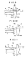
- an optical wavelength converter module 60 includes a lens 62 having two opposite conical surfaces 62a, 62b for converting the conical wavefront of the second harmonic 15′ into a plane wavefront.
- An optical wavelength converter module 70 according to the seventh embodiment illustrated in Figure 11 has a lens 72 having a concave conical surface 72a and an opposite convex conical surface 72b, the convex conical surface 72b being inclined at a greater angle than the concave conical surface 72a.
- the optical wavelength converter device 80 comprises a fiber Cherenkov type optical wavelength converter device 31, and a grating device 81, which is disposed in confronting relation to the exit end 12a of the cladding of the device 31.
- the grating device 81 comprises a grating 21 composed of equally spaced concentric patterns, which is identical to the grating according to the second embodiment shown in Figures 5 and 6, and the grating 21 being disposed on one surface of a transparent member 82 which is remote from the optical wavelength converter device 31.
- the wavefront of the second harmonic 15′ emitted from the cladding end 12a can be converted into a plane wavefront by passing through the grating device 81.
- the grating device 81 While the grating device 81 is spaced from the optical wavelength converter device 31 in the eighth embodiment, the grating device 81 may be held in intimate contact with the cladding end 12a of the device 31 in an optical wavelength converter module 90 according to the ninth embodiment illustrated in Figure 13.
- the optical wavelength converter device 100 comprises a fiber Cherenkov type optical wavelength converter device 31, and a graded-index lens 101, which is disposed in confronting relation to the exit end 12a of the cladding 12 of the device 31.
- the graded-index lens 101 may be positioned in close contact with the cladding end 12a.
- FIGS 15, 16 and 17 illustrate an optical wavelength converter device 110 according to the eleventh embodiment of the present invention.
- the optical wavelength converter device 110 is fabricated in the same manner as the optical wavelength converter device 10 according to the first embodiment shown in Figures 1 through 4.
- the end of the optical wavelength converter device 110 which will serve as an entrance end 110a for receiving light beams, is cut perpendicularly to the axis of the glass fiber.
- the other end 112a of cladding 112 is finished to an aspherical lens surface by a known grinding process. In this manner, the optical wavelength converter device 110 shown in Figures 15 and 16 is produced.
- the configuration of the cladding end 112a will be described later.
- the optical wavelength converter device 110 is used as shown in Figure 16 as the optical wavelength converter device 10 is used according to the first embodiment.
- the second harmonic 15′ is emitted out of the device 110 from the cladding end 112a.
- the fundamental wave 15 which has been guided through the core 111 is emitted from the end 111a of the core 111.
- a light beam 15 ⁇ , containing the second harmonic 15′, and the fundamental wave 15 then goes through a filter 18 which passes only the second harmonic 15′. Thereby, only the second harmonic 15′ is extracted by the filter 18.
- the second harmonic 15′ is converged into a small spot P by the cladding end 112a having an aspherical lens surface.
- the cladding 112 is thick enough for the second harmonic 15′ radiated into the cladding 112 at a phase matching angle ⁇ to be directly emitted out of the device 110 from the cladding end 112a without being totally reflected by the outer surface of the cladding 112.
- the cladding 112 is dimensioned to satisfy condition (1) above.
- the wavefront of the second harmonic 15′ traveling through the cladding 112 is oriented as indicated by the arrows W in Figure 17, in one plane which includes the core axis. Therefore, as a whole the wavefront is of a conical shape.
- the cladding end 112a is shaped as an aspherical lens surface, which is a combination of the conical surface J indicated by the broken line and a spherical surface K indicated by the dot-and-dash line, then the second harmonic 15′ emitted out of the cladding 112 has a convergent spherical wavefront.
- the configuration of the cladding end 112a will be represented in the y-z coordinate system shown in Figure 17. Since the optical wavelength converter device 110 is an optical system, which is symmetric with respect to its axis, it is sufficient to consider the cladding end 112a in the y-z coordinate system or the y-z plane.
- the wavefront of the emitted second harmonic 15′ becomes a convergent spherical wavefront, so that the second harmonic 15′ can be focused into a small beam spot P.
- an optical wavelength converter device 120 which includes a cladding 112 having an end 112a for emitting the second harmonic 15′, the cladding end 112a having a plane surface extending perpendicularly to the core axis, and a grating 121 of concentric patterns disposed on the surface of the cladding end 112a.
- the grating 121 may be formed by the photolithographic process.
- the diameter D of the cladding 112 is thick, ranging from 1mm to 3mm, for example, so that condition (1) given above can be satisfied. Therefore, the grating 121 can be formed on the cladding end 112a relatively easily.
- the radius rm of the mth circular pattern or line of the grating 121 will be described below.
- the position along the optical axis is represented by z, the position along the radial direction of the grating 121 by r, the refractive index of the cladding 112, the phase matching angle of the second harmonic 15′ by ⁇ , and the focal length by f. Since the optical wavelength converter device 120 is symmetric with respect to the axis thereof, only one sectional plane across the device 120 will be considered.
- the grating 121 may be used to converge the second harmonic 15′ onto the reflecting surface of an optical disc, for example.
- the radii of the circular patterns of the grating 121 should be determined also in view of the refraction of the second harmonic 15′ within the optical disc.
- the conical wavefront of the second harmonic 15′ can be converted into a convergent spherical wavefront.
- the second harmonic 15′ can be converged into a small beam spot P.
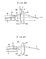
- FIG 20 shows an optical wavelength converter module 130 according to the thirteenth embodiment of the present invention.
- the optical wavelength converter module 130 comprises a fiber Cherenkov type optical wavelength converter device 131, identical to the previously described optical wavelength converter device, and a lens 132 disposed in confronting relation to the exit 112a of a cladding 112 of the optical wavelength converter device 131.
- the lens 132 has an aspherical surface 132a, facing the optical wavelength converter device 131, and a plane surface 132b, remote from the device 131.
- ⁇ 0 the angle at which the second harmonic 15′ is emitted from the optical wavelength converter device 131
- ⁇ the angle at which the conical surface j is in inclined
- n L the refractive index of the material of the lens 131
- the wavefront of the second harmonic 15′ that has passed through the lens 132 becomes a convergent spherical wavefront. Therefore, the second harmonic 15′ can be focused into a small beam spot P, as with the eleventh and twelfth embodiments.
- the plane lens surface may be positioned closely against the cladding end 112a.
- An optical wavelength converter module 140 according to the fourteenth embodiment shown in Figure 21 comprises an optical wavelength converter device 131 and a lens 142.
- the lens 142 has a conical surface 142a, which faces the optical wavelength converter device 131, and an opposite spherical surface 142b.
- the conical wavefront of the second harmonic 15′ is converted into a plane wavefront.
- the second harmonic 15′ then passes through the spherical lens surface 142b, the plane wavefront thereof is converted into a convergent spherical wavefront, so that the second harmonic 15′ can be converged into a small beam spot P.
- a combination of a lens having a conical surface identical to the lens surface 142a above and an opposite plane surface, and another lens having at least one spherical surface may be employed in place of the lens 142; and it can achieve the same function as the lens 142.
- the optical wavelength converter device 150 comprises a fiber Cherenkov type optical wavelength converter device 131, and a grating device 151 disposed in confronting relation to the exit end 112a of the cladding 112 of the device 31.
- the grating device 151 comprises a grating 153, composed of concentric patterns, which is disposed on one surface of a transparent member 152, which is remote from the optical wavelength converter device 131.
- the wavefront of the second harmonic 15′, emitted from the cladding end 112a can be converted into a convergent spherical wavefront by passing through the grating device 151.
- the configuration of the grating 153 will hereinafter be described in detail. It is assumed, as shown in Figure 23, that the position along the optical axis is represented by z, the position along the radial direction of the grating 153 by r, the angle at which the second harmonic 15′ is emitted from the cladding 112 by ⁇ °, and the focal length by f.
- the grating 153 can be fabricated by an electron beam lithographic process or a laser beam direct-writing process, or can be fabricated as a hologram using the system shown in Figure 24.
- the system of Figure 24 includes a lens 161, which has a concave conical surface for converting the plane wave 160 into the divergent wave 160′, which has a conical wavefront similar to the second harmonic 15′; semireflecting mirrors 162, 163; fully reflecting mirrors 164, 165; and a spherical lens 166, for converting the plane wave 160 into the convergent wave 160 ⁇ , which has a spherical wavefront.
- the grating 153 is formed by applying the divergent wave 160′ and the convergent wave 160 ⁇ coaxially to a photosensitive layer 160 on the transparent member 152.
- FIG 25 illustrates an optical wavelength converter module 170 according to the sixteenth embodiment of the present invention.
- the optical wavelength converter module 170 comprises an optical wavelength converter device 131 and a grating device 171, which has a grating 173 composed of concentric patterns.
- the grating 173 is formed on a surface of the transparent member 172 and converts the conical wavefront of the second harmonic 15′ into a divergent spherical wavefront.
- the second harmonic 15′ with its wavefront thus converted, is then converted into a parallel beam of an increased beam width by the collimator lens 174 which comprises a spherical lens.
- the parallel-beam second harmonic 15′ is then focused into a small beam spot P by the condenser lens 175 which is in the form of a spherical lens.
- grating devices 151, 171 in the fifteenth and sixteenth embodiments are spaced from the respective optical wavelength converter devices 131, they may be held intimately against the cladding ends 112a of the devices 131.
- the grating devices 151, 171 may be oriented such that the surfaces thereof, which support the gratings 153, 173, face the optical wavelength converter devices 131.
- Each of the optical wavelength converter devices described above is designed to convert a fundamental wave into a second harmonic.
- the present invention is also applicable to an optical wavelength converter device which converts a fundamental wave into a third harmonic, or to an optical wavelength converter device which converts two fundamental waves into a wave having a frequency which is the sum of or difference between the frequencies of the fundamental waves.
- the wavefront of a wavelength-converted wave emitted from a fiber type optical wavelength converter device can be converted into a plane wavefront
- the wavelength-converted wave can be focused into a small spot by passing through an ordinary spherical lens, as described above.
- the wavelength-converted wave can be focused into a small spot by being passed through a collimator lens and a condenser lens, each in the form of an ordinary spherical lens.
- wavelength-converted waves can be utilized in optical recording apparatus in which a light beam is to be focused into a small beam spot.
- the technology of wavelength conversion thus finds a wider range of applications than previous.
Landscapes
- Physics & Mathematics (AREA)
- General Physics & Mathematics (AREA)
- Optics & Photonics (AREA)
- Nonlinear Science (AREA)
- Optical Couplings Of Light Guides (AREA)
- Lasers (AREA)
Applications Claiming Priority (4)
| Application Number | Priority Date | Filing Date | Title |
|---|---|---|---|
| JP63186080A JPH0820657B2 (ja) | 1988-07-26 | 1988-07-26 | 光波長変換素子 |
| JP186081/88 | 1988-07-26 | ||
| JP186080/88 | 1988-07-26 | ||
| JP63186081A JPH0820658B2 (ja) | 1988-07-26 | 1988-07-26 | 光波長変換素子 |
Publications (3)
| Publication Number | Publication Date |
|---|---|
| EP0352751A2 true EP0352751A2 (de) | 1990-01-31 |
| EP0352751A3 EP0352751A3 (de) | 1991-04-03 |
| EP0352751B1 EP0352751B1 (de) | 1996-03-27 |
Family
ID=26503519
Family Applications (1)
| Application Number | Title | Priority Date | Filing Date |
|---|---|---|---|
| EP89113715A Expired - Lifetime EP0352751B1 (de) | 1988-07-26 | 1989-07-25 | Optische Wellenlängenkonverter-Einrichtung und optisches Wellenlängenkonverter-Modul |
Country Status (3)
| Country | Link |
|---|---|
| US (1) | US5416877A (de) |
| EP (1) | EP0352751B1 (de) |
| DE (1) | DE68926074T2 (de) |
Cited By (11)
| Publication number | Priority date | Publication date | Assignee | Title |
|---|---|---|---|---|
| EP0377988A3 (de) * | 1989-01-13 | 1991-09-11 | Kabushiki Kaisha Toshiba | Optische Wellenlängenkonverter-Einrichtung |
| EP0490369A1 (de) * | 1990-12-14 | 1992-06-17 | Sumitomo Electric Industries, Ltd. | Wellenlängen-Konverter |
| EP0615142A1 (de) * | 1993-03-08 | 1994-09-14 | Corning Incorporated | Kombiniertes optisches Element |
| EP0360122B1 (de) * | 1988-09-19 | 1995-12-27 | Hitachi, Ltd. | Generator für die zweite Harmonische und denselben benutzendes Informationssystem |
| WO1998018030A1 (en) * | 1996-10-21 | 1998-04-30 | Bicc Public Limited Company | Optical fibre with a grating on its end face |
| WO2001040835A2 (en) | 1999-12-06 | 2001-06-07 | Cidra Corporation | Large diameter optical waveguide, grating, and laser |
| WO2001067137A3 (en) * | 2000-03-06 | 2002-01-10 | Cidra Corp | Compression-tuned grating-based optical add/drop multiplexer |
| WO2001067142A3 (en) * | 2000-03-16 | 2002-02-28 | Cidra Corp | TEMPERATURE COMPENSATED BRAGG GRATING AND ASSOCIATED OPTICAL DEVICEs |
| EP1184339A3 (de) * | 2000-09-01 | 2002-09-04 | A.R.T.-Photonics GmbH | Optische Faser und Herstellungsverfahren für eine optische Faser |
| US6810178B2 (en) | 1998-12-04 | 2004-10-26 | Cidra Corporation | Large diameter optical waveguide having blazed grating therein |
| US6996316B2 (en) | 1999-09-20 | 2006-02-07 | Cidra Corporation | Large diameter D-shaped optical waveguide and coupler |
Family Cites Families (22)
| Publication number | Priority date | Publication date | Assignee | Title |
|---|---|---|---|---|
| US4081207A (en) * | 1976-07-01 | 1978-03-28 | Cincinnati Electronics Corporation | Scanning lens system |
| US4215274A (en) * | 1977-12-23 | 1980-07-29 | Kms Fusion, Inc. | X-ray detector with picosecond time resolution |
| US4255021A (en) * | 1979-04-20 | 1981-03-10 | The United States Of America As Represented By The United States Department Of Energy | Optical device with conical input and output prism faces |
| US4421379A (en) * | 1981-01-12 | 1983-12-20 | Grumman Aerospace Corporation | Multiple holographic lens |
| NL8204961A (nl) * | 1982-12-23 | 1984-07-16 | Philips Nv | Monomode optische transmissievezel met een taps eindgedeelte en werkwijze voor het vervaardigen daarvan. |
| JPS6026905A (ja) * | 1983-07-25 | 1985-02-09 | Hitachi Ltd | 球面ホログラムレンズ |
| US4730883A (en) * | 1983-11-28 | 1988-03-15 | Kei Mori | Photoradiator including light control device |
| JPH0638130B2 (ja) * | 1985-04-18 | 1994-05-18 | オリンパス光学工業株式会社 | 屈折率分布型レンズ |
| US4780877A (en) * | 1985-07-26 | 1988-10-25 | Polaroid Corporation | Optical fiber laser |
| US4768867A (en) * | 1985-09-02 | 1988-09-06 | Canon Kabushiki Kaisha | Aspherical single lens |
| US4721378A (en) * | 1985-09-24 | 1988-01-26 | David Volk | Condensing-image forming optical system for indirect ophthalmoscopy |
| JPS6315235A (ja) * | 1986-07-08 | 1988-01-22 | Fuji Photo Film Co Ltd | 光波長変換素子 |
| US4826299A (en) * | 1987-01-30 | 1989-05-02 | Canadian Patents And Development Limited | Linear deiverging lens |
| US4830447A (en) * | 1987-02-13 | 1989-05-16 | Fuji Photo Film Co., Ltd. | Optical wavelength conversion device |
| JPS63199328A (ja) * | 1987-02-16 | 1988-08-17 | Fuji Photo Film Co Ltd | 光波長変換素子 |
| US4767169A (en) * | 1987-02-26 | 1988-08-30 | Hoechst Celanese Corporation | Thin film waveguide electrooptic modulator |
| US4843494A (en) * | 1987-10-15 | 1989-06-27 | Polaroid Corporation | Data storage apparatus using optical servo tracks |
| JPH01287531A (ja) * | 1988-05-14 | 1989-11-20 | Sumitomo Electric Ind Ltd | 光源装置 |
| JP2686536B2 (ja) * | 1988-05-20 | 1997-12-08 | パイオニア株式会社 | ファイバー型光波長変換装置 |
| JPH01293326A (ja) * | 1988-05-20 | 1989-11-27 | Pioneer Electron Corp | ファイバー型光波長変換装置 |
| JP2738713B2 (ja) * | 1988-09-19 | 1998-04-08 | 株式会社日立製作所 | 第2高調波発生装置 |
| JP2525879B2 (ja) * | 1988-10-14 | 1996-08-21 | パイオニア株式会社 | ファイバ―型光波長変換素子 |
-
1989
- 1989-07-25 EP EP89113715A patent/EP0352751B1/de not_active Expired - Lifetime
- 1989-07-25 DE DE68926074T patent/DE68926074T2/de not_active Expired - Fee Related
- 1989-07-25 US US07/384,532 patent/US5416877A/en not_active Expired - Fee Related
Cited By (20)
| Publication number | Priority date | Publication date | Assignee | Title |
|---|---|---|---|---|
| EP0360122B1 (de) * | 1988-09-19 | 1995-12-27 | Hitachi, Ltd. | Generator für die zweite Harmonische und denselben benutzendes Informationssystem |
| EP0377988A3 (de) * | 1989-01-13 | 1991-09-11 | Kabushiki Kaisha Toshiba | Optische Wellenlängenkonverter-Einrichtung |
| US5377291A (en) * | 1989-01-13 | 1994-12-27 | Kabushiki Kaisha Toshiba | Wavelength converting optical device |
| EP0490369A1 (de) * | 1990-12-14 | 1992-06-17 | Sumitomo Electric Industries, Ltd. | Wellenlängen-Konverter |
| US5293444A (en) * | 1990-12-14 | 1994-03-08 | Sumitomo Electric Industries, Ltd. | Wavelength converter |
| EP0615142A1 (de) * | 1993-03-08 | 1994-09-14 | Corning Incorporated | Kombiniertes optisches Element |
| WO1998018030A1 (en) * | 1996-10-21 | 1998-04-30 | Bicc Public Limited Company | Optical fibre with a grating on its end face |
| US6810178B2 (en) | 1998-12-04 | 2004-10-26 | Cidra Corporation | Large diameter optical waveguide having blazed grating therein |
| US6996316B2 (en) | 1999-09-20 | 2006-02-07 | Cidra Corporation | Large diameter D-shaped optical waveguide and coupler |
| WO2001040835A3 (en) * | 1999-12-06 | 2002-03-07 | Cidra Corp | Large diameter optical waveguide, grating, and laser |
| US6982996B1 (en) | 1999-12-06 | 2006-01-03 | Weatherford/Lamb, Inc. | Large diameter optical waveguide, grating, and laser |
| WO2001040835A2 (en) | 1999-12-06 | 2001-06-07 | Cidra Corporation | Large diameter optical waveguide, grating, and laser |
| US7437043B2 (en) | 1999-12-06 | 2008-10-14 | Weatherford/Lamb, Inc. | Large diameter optical waveguide, grating and laser |
| US8111963B2 (en) | 1999-12-06 | 2012-02-07 | Weatherford/Lamb, Inc. | Large diameter optical waveguide, grating and laser |
| US8244088B2 (en) | 1999-12-06 | 2012-08-14 | Weatherford/Lamb, Inc. | Large diameter optical waveguide, grating and laser |
| WO2001067137A3 (en) * | 2000-03-06 | 2002-01-10 | Cidra Corp | Compression-tuned grating-based optical add/drop multiplexer |
| WO2001067142A3 (en) * | 2000-03-16 | 2002-02-28 | Cidra Corp | TEMPERATURE COMPENSATED BRAGG GRATING AND ASSOCIATED OPTICAL DEVICEs |
| US6621957B1 (en) | 2000-03-16 | 2003-09-16 | Cidra Corporation | Temperature compensated optical device |
| EP1184339A3 (de) * | 2000-09-01 | 2002-09-04 | A.R.T.-Photonics GmbH | Optische Faser und Herstellungsverfahren für eine optische Faser |
| US6564587B2 (en) | 2000-09-01 | 2003-05-20 | Viatcheslav Artiouchenko | Method of producing an optical fiber by gathering material from a molten bath |
Also Published As
| Publication number | Publication date |
|---|---|
| EP0352751A3 (de) | 1991-04-03 |
| DE68926074T2 (de) | 1996-08-14 |
| DE68926074D1 (de) | 1996-05-02 |
| US5416877A (en) | 1995-05-16 |
| EP0352751B1 (de) | 1996-03-27 |
Similar Documents
| Publication | Publication Date | Title |
|---|---|---|
| US7184386B2 (en) | Integrated type optical head with sheet waveguide and light coupler | |
| US5251060A (en) | Light-source unit | |
| EP0468410B1 (de) | Optische Beugungslinse | |
| EP0372345B1 (de) | Lichtquelle | |
| EP0352751B1 (de) | Optische Wellenlängenkonverter-Einrichtung und optisches Wellenlängenkonverter-Modul | |
| US4892375A (en) | Fiber-type light conversion device | |
| US5029976A (en) | Optical wavelength converter device and optical wavelength converter module | |
| EP0360122B1 (de) | Generator für die zweite Harmonische und denselben benutzendes Informationssystem | |
| EP0342523B1 (de) | Erzeugung paralleler, frequenzverdoppelter Strahlen mittels einer optischen Faser | |
| EP0377988B1 (de) | Optische Wellenlängenkonverter-Einrichtung | |
| US4611883A (en) | Two-dimensional optics element for correcting aberrations | |
| US5117433A (en) | Second harmonic generator for obtaining an aberration free plane wave and information processing system using the same | |
| US4817205A (en) | Bimodal optical fiber communication system using graded index fiber | |
| EP0490291B1 (de) | Lichtquelleneinrichtung | |
| US4688883A (en) | Integrated optics stress transducer | |
| US4981337A (en) | Fibre-type light wavelength coversion device | |
| US5119458A (en) | Fibre-type wavelength converison device | |
| JPH0820657B2 (ja) | 光波長変換素子 | |
| US5197110A (en) | Wavelength converting device having a surrounding resin layer | |
| US4693565A (en) | Collimator lens | |
| EP0490369B1 (de) | Wellenlängen-Konverter | |
| JPH0820658B2 (ja) | 光波長変換素子 | |
| JPH0545656U (ja) | 光源装置 | |
| Belostotsky et al. | Integrated-optical head on lithium niobate | |
| JPH02205828A (ja) | ファイバー型光波長変換装置 |
Legal Events
| Date | Code | Title | Description |
|---|---|---|---|
| PUAI | Public reference made under article 153(3) epc to a published international application that has entered the european phase |
Free format text: ORIGINAL CODE: 0009012 |
|
| AK | Designated contracting states |
Kind code of ref document: A2 Designated state(s): DE FR GB |
|
| PUAL | Search report despatched |
Free format text: ORIGINAL CODE: 0009013 |
|
| AK | Designated contracting states |
Kind code of ref document: A3 Designated state(s): DE FR GB |
|
| 17P | Request for examination filed |
Effective date: 19910524 |
|
| 17Q | First examination report despatched |
Effective date: 19930518 |
|
| GRAH | Despatch of communication of intention to grant a patent |
Free format text: ORIGINAL CODE: EPIDOS IGRA |
|
| GRAA | (expected) grant |
Free format text: ORIGINAL CODE: 0009210 |
|
| AK | Designated contracting states |
Kind code of ref document: B1 Designated state(s): DE FR GB |
|
| REF | Corresponds to: |
Ref document number: 68926074 Country of ref document: DE Date of ref document: 19960502 |
|
| ET | Fr: translation filed | ||
| PLBE | No opposition filed within time limit |
Free format text: ORIGINAL CODE: 0009261 |
|
| STAA | Information on the status of an ep patent application or granted ep patent |
Free format text: STATUS: NO OPPOSITION FILED WITHIN TIME LIMIT |
|
| 26N | No opposition filed | ||
| REG | Reference to a national code |
Ref country code: GB Ref legal event code: IF02 |
|
| PGFP | Annual fee paid to national office [announced via postgrant information from national office to epo] |
Ref country code: FR Payment date: 20040720 Year of fee payment: 16 |
|
| PGFP | Annual fee paid to national office [announced via postgrant information from national office to epo] |
Ref country code: GB Payment date: 20040721 Year of fee payment: 16 |
|
| PGFP | Annual fee paid to national office [announced via postgrant information from national office to epo] |
Ref country code: DE Payment date: 20040831 Year of fee payment: 16 |
|
| PG25 | Lapsed in a contracting state [announced via postgrant information from national office to epo] |
Ref country code: GB Free format text: LAPSE BECAUSE OF NON-PAYMENT OF DUE FEES Effective date: 20050725 |
|
| PG25 | Lapsed in a contracting state [announced via postgrant information from national office to epo] |
Ref country code: DE Free format text: LAPSE BECAUSE OF NON-PAYMENT OF DUE FEES Effective date: 20060201 |
|
| GBPC | Gb: european patent ceased through non-payment of renewal fee |
Effective date: 20050725 |
|
| PG25 | Lapsed in a contracting state [announced via postgrant information from national office to epo] |
Ref country code: FR Free format text: LAPSE BECAUSE OF NON-PAYMENT OF DUE FEES Effective date: 20060331 |
|
| REG | Reference to a national code |
Ref country code: FR Ref legal event code: ST Effective date: 20060331 |