EP0352813B1 - Dispositif d'alimentation de feuilles pour machine de reproduction et de traitement - Google Patents
Dispositif d'alimentation de feuilles pour machine de reproduction et de traitement Download PDFInfo
- Publication number
- EP0352813B1 EP0352813B1 EP89114001A EP89114001A EP0352813B1 EP 0352813 B1 EP0352813 B1 EP 0352813B1 EP 89114001 A EP89114001 A EP 89114001A EP 89114001 A EP89114001 A EP 89114001A EP 0352813 B1 EP0352813 B1 EP 0352813B1
- Authority
- EP
- European Patent Office
- Prior art keywords
- sheet
- guide plate
- sheet feeding
- roller
- movable
- Prior art date
- Legal status (The legal status is an assumption and is not a legal conclusion. Google has not performed a legal analysis and makes no representation as to the accuracy of the status listed.)
- Expired - Lifetime
Links
Images


Classifications
-
- B—PERFORMING OPERATIONS; TRANSPORTING
- B65—CONVEYING; PACKING; STORING; HANDLING THIN OR FILAMENTARY MATERIAL
- B65H—HANDLING THIN OR FILAMENTARY MATERIAL, e.g. SHEETS, WEBS, CABLES
- B65H3/00—Separating articles from piles
- B65H3/46—Supplementary devices or measures to assist separation or prevent double feed
- B65H3/52—Friction retainers acting on under or rear side of article being separated
- B65H3/5207—Non-driven retainers, e.g. movable retainers being moved by the motion of the article
- B65H3/5215—Non-driven retainers, e.g. movable retainers being moved by the motion of the article the retainers positioned under articles separated from the top of the pile
- B65H3/5223—Retainers of the pad-type, e.g. friction pads
Definitions
- the present invention relates to a sheet feeding device incorporated in an image developing and processing machine according to the preamble of claim 1.
- a known generic sheet feeding device is disclosed in the GB-A-2 190 363.
- This sheet feeding device comprises a movable sheet guide plate, which is moved if sheets fed by a sheet feeding roller are fed too quickly with respect to the feeding speed of register roller means.
- the movable sheet guide plate is pivotally supported at an upstream end thereof and after swiveling about more than a predetermined angle a detecting means in the form of a microswitch detects a situatuion in which the feeding rollers are stopped.
- the transported sheets may warp differently, and therefore a correct detection of the situation in which the feeding rollers have to be stopped can not be guaranteed.
- the US-A-4 025 187 shows a sheet feeding device which comprises a movable sheet guide plate pivoted at an upstream end thereof.
- This sheet guide plate serves to push and flatten a buckle of a sheet to be transported
- the mechanical functioning of the sheet guide plate of the US-A-4 025 187 corresponds to that of the GB-A-2 190 363.
- Such a pivoted movable sheet guide plate cannot be pivoted at a downstream end of it, since the feeding of the sheets would be blocked.
- a sheet feeding device incorporated in an image developing and processing device such as a copy machine, a printing press or the like is in general adapted to take up and feed a plurality of sheets one by one by means of a selectively driven sheet feeding roller from the stack thereof positioned on a sheet feeding base to a pair of register rollers or timing rollers and then to transport the sheet by the register rollers to an image developing and processing means such as a form cylinder or a copying photosensitive element drum at a timing that is in timed relation to the operation of the image developing and processing means.
- This type of sheet feeding devices are well known in the art and are shown and described for example in the Japanese Patent Publication No. 58-7582, the Japanese Patent Laying Open Publication No. 62-157145 and the like.
- each sheet fed by the sheet feeding roller from the sheet feeding base toward the image developing and processing means once stops with its leading edge contacting with the register rollers at the contact parts therebetween, and is transported at a predetermined timing to the image developing and processing means by the register rollers which are started to rotate at a predetermined timing. Since the sheet feeding roller continues to rotate at least for a little while even after a sheet has arrived at and contacted with the register rollers at the leading edge thereof, the sheet generates in itself a ridge-like curvature growing across the moving direction thereof between the sheet feeding roller and the register rollers before the latter rollers begin to transport the sheet towards the image developing and processing means.
- a sheet guide passage defined between the sheet feeding roller and the register rollers must have a relatively large space extended in the direction of the curvature growth and, accordingly, an upper guide plate which defines the upper boundary of the sheet guide passage is in general bent upward at the front part thereof to extend the upper space of the passage.
- the sheet guide passage being constructed as above, if the leading end of the sheet being fed through the passage has been curled up, it comes into collision against the upwardly bent portion of the upper guide plate and is prevented from moving further, resulting in an abnormal sheet feeding and causing a sheet jamming. Especially, if such a situation occurred when a relatively tough sheet such as a cardboard or the like being used, it could not be fed further because of the jamming.
- the excessive feeding of the sheet is detected by a flexing deformation of the movable sheet guide plate, which is supported by a curved convex upper guide plate. Therefore an exactly predefined flexing deformation is guaranteed so that the operating reliability during the feeding of sheets is considerably enhanced.
- the sheet guide plate is fixed with its downstream end to the upper guide plate and when deformation of the sheet guide plate occurs, the sheet guide plate is fitted close to the upper guide plate behind it. Since the detecting means is provided on the upstream end of the sheet guide plate, a stopping of the feeding rollers will be effected exactly when this is really desired.
- the sheet feeding device is adapted to prevent sheet from generating too much curvature, thereby avoiding the occurrence of sheet feeding fault due to the excess curvature of sheet.
- the displacing of the sheet guide member effected according to the growth of the curvature in the sheet being fed extends the space in the sheet guide passage according to the growth of the curvature in the sheet which allows the sheet to deform arcuately.
- the sheet guide passage does not define an excessive space, so that the situation is prevented from occurring wherein sheet collides at the leading edge thereof against the surface of the guide plate which would otherwise define an extended space and is accordingly impeded from moving further, and in the later stage the guide plate allows the sheet to deform arcuately, thereby preserving a positive sheet feeding.
- the extent of arcuate deformation of the sheet formed between the sheet feeding roller and the register roller means can positively be detected based upon the displacement of the movable sheet guide member, and the rotation of the sheet feeding roller is stopped when a predetermined extent of the curvature has been reached, to prevent the sheet from deforming more above the predetermined extent and to prevent sheet feeding fault from occurring due to an excessive curvature of the sheet.
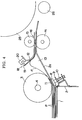
- Figs. 1 through 4 show a preferred embodiment of the sheet feeding device of the present invention.
- 1 denotes a sheet feeding base, on which a plurality of sheets P are stacked and which is adapted to be moved up and down in a suitable manner well known in the art by an actuator not shown in the figures that is controlled by an electric controller also not shown in the figures.
- a vertical wall plate 2 is fixedly provided at the end of the sheet feeding base 1 which is the right end as viewed in the figures, i.e. the downstream end as viewed along the sheet feeding direction, and serves to position the leading edges of the sheets P stacked on the base 1. As shown in Fig. 1, the upper end of the wall plate is slightly bent in the downstream direction.
- a sheet feeding roller 3 made rubber or other similar suitable material having a relatively high coefficient of friction.
- the sheet feeding roller 3 is rotatably supported by way of a support shaft 4 from side plates 5 positioned on both sides of the roller.
- the support shaft 4 is drivingly connected with a transmission belt 7 by way of an electromagnetic clutch 6 and is rotationally driven in the anti-clockwise direction as viewed in Fig. 1 only during the clutch 6 is in its engaged state.
- the sheet feeding roller 3 is rotationally driven in the anti-clockwise direction as viewed in Fig. 1 during the period when the electromagnetic clutch 6 is active.
- the operation of the clutch is also controlled by the electric controller.
- a sheet separating pad holder 8 Near the upper end of the wall plate 2 is provided a sheet separating pad holder 8, the upper surface of which opposes to the cylindrical outer surface of the sheet feeding roller 3.
- the pad holder 8 is supported by a bracket 9 secured to the wall plate 2 so that it may move relative to the bracket substantially in the direction along the radius of the sheet feeding roller 3, and is biased by the force exerted by a compression coil spring 10 against the cylindrical outer surface of the roller 3.
- a sheet separating pad 11 is fixedly attached to the upper surface of the pad holder 8.
- the pad is made of a material having a relatively high coefficient of friction such as rubber, its affinities, or cork, and its upper surface opposes to and substantially abuts with the outer cylindrical surface of the sheet feeding roller 3.
- a sheet feeding passage or sheet guide passage 13 is defined by both fixed lower and upper guide plates 2a, 12 and a movable sheet guide plate 17 downstream of the sheet feeding roller 3 and upstream of the image developing and processing section consisting of a form cylinder 25 and a press roller 26 corresponding thereto.
- the sheet feeding passage 13 extends from the sheet feeding roller 3 toward the image developing and processing section and at the location near the downstream end of the passage is positioned a register roller means 16 consisting of a pair of upper and lower roller elements 14 and 15, respectively.
- the roller elements rotatably contact with each other at their cylindrical outer surface.
- the roller element 14 is a driving roller selectively rotated in the clockwise direction as viewed in Fig. 1 by an actuator not shown in the figures and the roller element 15 is a driven roller rotated by the element 14.
- the fixed upper guide plate 12 includes an upstream and a downstream segments.
- the upstream segment is bent upward between the sheet feeding roller 3 and the register roller means 16 so that the sheet being fed can generate a curvature substantially across the sheet feeding direction as shown in Fig. 4.
- the downstream segment extends substantially in the horizontal direction.
- the fixed lower guide plate 2a includes an upstream and a downstream segments.
- the upstream segment is inclined up as viewed in the downstream direction and the downstream segment extends substantially in the horizontal direction.
- the movable sheet guide plate 17 which is made of any flexible material such as a plastic film or the like is positioned between the lower guide plate 2a and the upper guide plate 12 and extends substantially along of the sheet feeding passage 13.
- the movable guide plate 17 is secured to the under surface of the upper guide plate 12 at its end 17a adjacent the register roller means 16 and defines a free end at the opposite end 17b near the roller 3.
- the sheet guide plate 17 can deform elastically in the upward and downward directions as viewed in Fig. 1 to bend arcuately as shown in Figs. 3 and 4 following the curving deformation of sheet and maintains in its free state the generally planner shape to define in combination with the lower guide plate 2a the sheet feeding passage 13 having substantially a wedge shape.
- a tongue-like movable element 19 of a curvature detector 18 is fixed to the free end 17b of the sheet guide plate 17.
- the curvature detector 18 is comprised of the above mentioned movable element 19 and a photoelectric sensor 20 secured to the upper end of the upper guide plate 12.
- the sensor includes a light transmitter and a light receiver and defines a light passage therebetween which is selectively intercepted by the movable element.
- the detector is able to determine that a predetermined extent of curvature has been reached by the deformation of a sheet when the movable guide plate 17 has made an arcuate elastic deformation to a predetermined extent, i.e., in this embodiment, when the movable guide plate 17 has elastically deformed substantially to abut with the bent part of the upper guide plate 12 as shown in Fig. 4 and the movable element 19 has arrived at the position where it intervenes in the light passage of the photoelectric sensor 20.
- the sensor 20 varies its output voltage when the movable element 19 has reached at the intervening position and supplies an output signal to the electric controller, which in turn sends its command signal to the electromagnetic clutch for disengaging it.
- the sheet feeding roller 3 is rotationally driven in the anti-clockwise direction as viewed in Fig. 1.
- the upper most one of the sheets P stacked on the sheet feeding base 1 is fed by the roller 3 in the sheet feeding direction to enter between the roller 3 and the sheet separating pad 11, and is transported toward the contact parts between the roller elements 14 and 15 of the register roller means 16 with the guide served by the both the lower guide plate 2a and the sheet guide plate 17.
- the movable guide plate 17 maintains the generally planner shape and defines a substantially straight wedge-like sheet feeding passage 13 in corporation with the lower guide plate 2a, even though the sheet P to be fed is curled up at the front end thereof, it may not collide with any surface of the plates defining the sheet feeding passage 13 and may not hindered from moving forward.
- the sheet guide plate 17 elastically deforms to its full extent where it substantially abuts with the curved part of the upper guide plate 12 as shown in Fig. 4 and does not deform any more.
- the movable element 19 intervenes in the light passage of the photoelectric sensor 20, and the sensor determines that the curvature of the sheet has reached a predetermined extent, and the electromagnetic clutch 6 is disengaged to cease the rotation of the feeding roller 3 in the anti-clockwise direction as viewed in Fig. 1.
- the roller 3 is stopped to prevent the curvature of the sheet from increasing excessively and to prevent the front extremity of the sheet P from pulling out from the contact parts between the roller elements 14 and 15 of the register roller means 16.
- the sheet guide plate 17 As will be realized from the function of the sheet guide plate 17, it must have both a sufficient flexibility to ensure the elastic deformability permitting itself to bend according to the arcuate deformation of the sheet which is supplest among the sheets intended to be used and a sufficient rigidity to retain its planer shape in the free state.
- a contact type microswitch may be used as a curvature detector in the first through third embodiments in place of the photoelectric sensor.
- the movable sheet guide member is not limited to a plate or a sheet, it may take any suitable form such as, for example, a plurality of wire elements or a mesh member extending between the sheet feeding roller and the register roller means.
- a sheet feeding device for taking up and feeding a plurality of sheets one by one by a selectively driven sheet feeding roller from the stack thereof positioned on a sheet feeding base to a register roller means and for transporting the sheet to an image developing and processing device at a predetermined timing by the register roller means;
- the feeding device comprising a movable sheet guide member provided between the feeding roller and the register roller means which is adapted to be displaced by the curving deformation of a sheet between the feeding roller and the register roller means in the direction of the growing of the curving deformation.
- the feeding device may further comprise a detecting means for sensing the displacement of the sheet guide member to determine based upon the displacement that a predetermined curvature of a sheet has been reached, and a means for stopping the rotation of the feeding roller in response to the detection by the detecting means so as to prevent the sheet from deforming excessively.
Landscapes
- Engineering & Computer Science (AREA)
- Mechanical Engineering (AREA)
- Feeding Of Articles By Means Other Than Belts Or Rollers (AREA)
- Delivering By Means Of Belts And Rollers (AREA)
- Sheets, Magazines, And Separation Thereof (AREA)
- Paper Feeding For Electrophotography (AREA)
Claims (3)
- Dispositif d'alimentation de feuilles pour une machine de traitement et de reproduction d'image comprenant un support d'alimentation de feuilles (1) sur lequel sont empilées une pluralité de feuilles, un rouleau d'alimentation de feuilles commandé de manière sélective (3) pour prendre et alimenter une par une les feuilles provenant de ladite pile, des moyens à rouleaux d'alignement (14, 15) pour transférer les feuilles vers la machine de traitement et de reproduction d'image (25, 26) à un rythme prédéterminé, des plaques fixes de guidage inférieure et supérieure (2a, 12) définissant un passage de guidage de feuille (13) pour guider les feuilles fournies par ledit rouleau d'alimentation de feuilles en direction desdits moyens à rouleaux d'alignement, une plaque mobile de guidage de feuille (17) disposée dans ledit passage de guidage de feuilles de manière à être inclinée par une déformation en forme d'arc de la feuille dans le passage de guidage en raison d'une suralimentation de la feuille par ledit rouleau d'alimentation de feuilles (3) relative au transfert de la feuille par lesdits moyens à rouleaux d'alignement (14, 15), et des moyens de détection (19, 20) pour détecter un mouvement de ladite plaque mobile de guidage de feuille (17) afin d'envoyer un signal pour commander l'entraînement sélectif dudit rouleau d'alimentation de feuilles (3) de manière à ne pas augmenter davantage la déformation en forme d'arc de la feuille, caractérisé en ce que ladite plaque de guidage supérieure (12) présente une surface convexe en direction dudit passage de guidage de feuille (13), ladite plaque mobile de guidage de feuille (17) est flexible de façon élastique et est adaptée pour s'étendre davantage sur ladite surface convexe de ladite plaque de guidage supérieure (12) en partant d'une extrémité en aval de celle-ci lorsqu'elle est sollicitée par la déformation en forme d'arc de la feuille à mesure que la déformation en forme d'arc de la feuille augmente, et lesdits moyens de détection (19, 20) comprennent un (19) des éléments de commutation coopérants (19, 20) monté pratiquement à une extrémité amont de ladite plaque mobile de guidage de feuille (17).
- Dispositif d'alimentation de feuilles suivant la revendication 1, caractérisé en ce que l'extrémité amont de ladite surface convexe de ladite plaque de guidage supérieure (12) est courbée en s'écartant de ladite plaque de guidage de feuille inférieure (2a) et le segment aval de ladite surface convexe s'étend de manière importante dans la direction d'alimentation, la plaque mobile de guidage de feuille (17) étant fixée à ladite plaque de guidage supérieure (12) dans une partie d'extrémité aval (17a) de celle-ci.
- Dispositif d'alimentation de feuilles suivant la revendication 1 ou 2, caractérisé en ce que ledit élément (19) desdits éléments de commutation coopérants (19, 20) est un élément semblable à une languette et est adapté pour être détecté par un capteur photoélectrique (20) formant l'autre élément desdits éléments de commutation coopérants (19, 20).
Applications Claiming Priority (2)
| Application Number | Priority Date | Filing Date | Title |
|---|---|---|---|
| JP191225/88 | 1988-07-29 | ||
| JP63191225A JP2651602B2 (ja) | 1988-07-29 | 1988-07-29 | 給紙装置 |
Publications (3)
| Publication Number | Publication Date |
|---|---|
| EP0352813A2 EP0352813A2 (fr) | 1990-01-31 |
| EP0352813A3 EP0352813A3 (en) | 1990-06-27 |
| EP0352813B1 true EP0352813B1 (fr) | 1994-01-12 |
Family
ID=16270977
Family Applications (1)
| Application Number | Title | Priority Date | Filing Date |
|---|---|---|---|
| EP89114001A Expired - Lifetime EP0352813B1 (fr) | 1988-07-29 | 1989-07-28 | Dispositif d'alimentation de feuilles pour machine de reproduction et de traitement |
Country Status (4)
| Country | Link |
|---|---|
| US (1) | US5022642A (fr) |
| EP (1) | EP0352813B1 (fr) |
| JP (1) | JP2651602B2 (fr) |
| DE (1) | DE68912223T2 (fr) |
Families Citing this family (25)
| Publication number | Priority date | Publication date | Assignee | Title |
|---|---|---|---|---|
| JP2811952B2 (ja) * | 1990-10-22 | 1998-10-15 | ミノルタ株式会社 | シート搬送装置 |
| US5293204A (en) * | 1990-10-25 | 1994-03-08 | Mitsubishi Denki Kabushiki Kaisha | Copier with a superposed-sheet separation mechanism |
| GB2259499B (en) * | 1991-09-11 | 1995-11-22 | Xerox Corp | Sheet feeding apparatus |
| JPH05162877A (ja) * | 1991-12-17 | 1993-06-29 | Sumitomo Rubber Ind Ltd | 給紙装置の用紙分離部材 |
| JP2774750B2 (ja) * | 1993-02-26 | 1998-07-09 | 東北リコー株式会社 | 給紙装置における給紙ガイド機構 |
| US5394229A (en) * | 1993-06-29 | 1995-02-28 | Xerox Corporation | Retard feed apparatus with noise suppression device |
| JPH07267423A (ja) * | 1994-03-30 | 1995-10-17 | Brother Ind Ltd | 用紙搬送装置 |
| JP3309566B2 (ja) * | 1994-05-16 | 2002-07-29 | 富士ゼロックス株式会社 | 用紙搬送装置 |
| TW341955U (en) * | 1994-09-30 | 1998-10-01 | Mita Industrial Co Ltd | Device for conveying sheet members |
| US5632478A (en) * | 1995-04-03 | 1997-05-27 | Xerox Corporation | Cam idler for deskew of long sheets and buckle length latitude |
| JP3434144B2 (ja) * | 1996-10-09 | 2003-08-04 | シャープ株式会社 | シート給送装置 |
| US5904350A (en) * | 1997-01-31 | 1999-05-18 | Tektronix, Inc. | Apparatus and method for deskewing media in a printer |
| KR100307467B1 (ko) * | 1997-03-27 | 2001-11-17 | 이토가 미찌야 | 용지의스큐교정기능을갖는급지장치 |
| EP1306328B1 (fr) * | 2001-10-26 | 2006-05-17 | Ricoh Company, Ltd. | Procédé et dispositif d'alimentation en feuilles pour supprimer des bruits percussives |
| US6612562B2 (en) * | 2001-12-21 | 2003-09-02 | Pitney Dowes Inc. | Method and system for feeding media to a printer |
| JP4385627B2 (ja) * | 2003-03-24 | 2009-12-16 | 富士ゼロックス株式会社 | シート搬送装置及びこれを用いたシート処理装置 |
| JP4342249B2 (ja) * | 2003-09-01 | 2009-10-14 | 株式会社東芝 | 紙葉類分離搬送装置 |
| US7401551B2 (en) | 2004-02-25 | 2008-07-22 | Riso Kagaku Corporation | Stencil printing machine |
| US7613420B2 (en) * | 2005-02-23 | 2009-11-03 | Lexmark International, Inc. | Uniform entry of media into an alignment nip |
| US7431286B2 (en) * | 2005-03-04 | 2008-10-07 | Hewlett-Packard Development Company, L.P. | Media stack measurement and method |
| JP4296439B2 (ja) * | 2006-06-15 | 2009-07-15 | セイコーエプソン株式会社 | 記録装置 |
| JP2010089912A (ja) * | 2008-10-08 | 2010-04-22 | Riso Kagaku Corp | 印刷装置の給紙機構 |
| JP5140631B2 (ja) * | 2009-05-21 | 2013-02-06 | 京セラドキュメントソリューションズ株式会社 | 画像形成装置 |
| US10469688B2 (en) * | 2016-06-08 | 2019-11-05 | Canon Finetech Nisca Inc. | Conveyance apparatus, image reading apparatus, and image forming apparatus |
| US20200307934A1 (en) * | 2019-03-25 | 2020-10-01 | Toshiba Tec Kabushiki Kaisha | Sheet alignment in sheet conveying device |
Family Cites Families (7)
| Publication number | Priority date | Publication date | Assignee | Title |
|---|---|---|---|---|
| JPS5242384B2 (fr) | 1972-10-25 | 1977-10-24 | ||
| US4025187A (en) | 1974-09-05 | 1977-05-24 | Xerox Corporation | Buckle control system |
| JPS5854056B2 (ja) * | 1979-05-18 | 1983-12-02 | 株式会社リコー | 原稿供給装置に於ける原稿後縁通過検出装置 |
| JPS5851857B2 (ja) * | 1979-05-23 | 1983-11-18 | 株式会社リコー | 原稿供給装置に於ける原稿後端通過検出装置 |
| JPS59127041U (ja) * | 1983-02-10 | 1984-08-27 | 松下電器産業株式会社 | 複写機 |
| JPS62157145A (ja) * | 1985-12-27 | 1987-07-13 | Riso Kagaku Corp | 給紙装置 |
| GB2190363A (en) * | 1986-04-29 | 1987-11-18 | Wofenet Limited | Semi automatic paper cassette |
-
1988
- 1988-07-29 JP JP63191225A patent/JP2651602B2/ja not_active Expired - Fee Related
-
1989
- 1989-07-27 US US07/385,362 patent/US5022642A/en not_active Expired - Lifetime
- 1989-07-28 EP EP89114001A patent/EP0352813B1/fr not_active Expired - Lifetime
- 1989-07-28 DE DE89114001T patent/DE68912223T2/de not_active Expired - Fee Related
Also Published As
| Publication number | Publication date |
|---|---|
| EP0352813A3 (en) | 1990-06-27 |
| DE68912223T2 (de) | 1994-05-11 |
| EP0352813A2 (fr) | 1990-01-31 |
| DE68912223D1 (de) | 1994-02-24 |
| JPH0243145A (ja) | 1990-02-13 |
| US5022642A (en) | 1991-06-11 |
| JP2651602B2 (ja) | 1997-09-10 |
Similar Documents
| Publication | Publication Date | Title |
|---|---|---|
| US5022642A (en) | Sheet feeding device for a image developing and processing machine | |
| US4589645A (en) | Document set separator and stack height sensor | |
| US5033731A (en) | Dual mode stack height and sheet delivery detector | |
| US5026042A (en) | Sheet feeder for copiers and printers | |
| US5435540A (en) | Apparatus and method for sheet feeding and separating using retard roll relief/enhancement | |
| EP0393589B1 (fr) | Appareil de délivrance de papier en continu | |
| EP0349012A1 (fr) | Dispositif d'avancement du papier | |
| CN107472947B (zh) | 输送装置、图像读取装置和图像形成装置 | |
| EP0875474B1 (fr) | Patin d'appui à friction pour la séparation de feuilles | |
| GB1565629A (en) | Sheet feed mechanism employing a roller | |
| US4928951A (en) | Automatic paper feed device | |
| US6354585B1 (en) | Image forming apparatus and sheet feeder for the same | |
| EP0546722B1 (fr) | Appareil de positionnement et d'alimentation de feuilles | |
| CA1224221A (fr) | Dispositif d'alimentation en papier et de separation de feuilles avec reglage de la force appliquee au papier | |
| EP0346220B1 (fr) | Procédé pour l'alimentation individuelle d'une feuille et dispositif à cet effet | |
| US5727784A (en) | Paper feeder | |
| WO1989005766A1 (fr) | Dispositif de separation de feuille par frottement du bas d'une pile | |
| US5192068A (en) | Sheet feeding and separating apparatus with an improved entrance guide | |
| US11560283B2 (en) | Sheet feeding apparatus, image reading apparatus, and image forming apparatus | |
| US4750726A (en) | Automatic document feeder/separator for copiers | |
| US5411247A (en) | Automatic document feeder with smooth sheet feeding mechanism | |
| US5465948A (en) | Sheet feeding and separating apparatus | |
| US4750727A (en) | Automatic document feeder for copiers | |
| JP3343174B2 (ja) | シュレッダの給紙装置 | |
| JPH07117899A (ja) | 給紙装置 |
Legal Events
| Date | Code | Title | Description |
|---|---|---|---|
| PUAI | Public reference made under article 153(3) epc to a published international application that has entered the european phase |
Free format text: ORIGINAL CODE: 0009012 |
|
| AK | Designated contracting states |
Kind code of ref document: A2 Designated state(s): DE FR GB |
|
| PUAL | Search report despatched |
Free format text: ORIGINAL CODE: 0009013 |
|
| AK | Designated contracting states |
Kind code of ref document: A3 Designated state(s): DE FR GB |
|
| 17P | Request for examination filed |
Effective date: 19901031 |
|
| 17Q | First examination report despatched |
Effective date: 19920416 |
|
| GRAA | (expected) grant |
Free format text: ORIGINAL CODE: 0009210 |
|
| AK | Designated contracting states |
Kind code of ref document: B1 Designated state(s): DE FR GB |
|
| REF | Corresponds to: |
Ref document number: 68912223 Country of ref document: DE Date of ref document: 19940224 |
|
| ET | Fr: translation filed | ||
| PLBE | No opposition filed within time limit |
Free format text: ORIGINAL CODE: 0009261 |
|
| STAA | Information on the status of an ep patent application or granted ep patent |
Free format text: STATUS: NO OPPOSITION FILED WITHIN TIME LIMIT |
|
| 26N | No opposition filed | ||
| REG | Reference to a national code |
Ref country code: GB Ref legal event code: IF02 |
|
| PGFP | Annual fee paid to national office [announced via postgrant information from national office to epo] |
Ref country code: DE Payment date: 20060714 Year of fee payment: 18 Ref country code: FR Payment date: 20060714 Year of fee payment: 18 |
|
| PGFP | Annual fee paid to national office [announced via postgrant information from national office to epo] |
Ref country code: GB Payment date: 20060720 Year of fee payment: 18 |
|
| GBPC | Gb: european patent ceased through non-payment of renewal fee |
Effective date: 20070728 |
|
| PG25 | Lapsed in a contracting state [announced via postgrant information from national office to epo] |
Ref country code: DE Free format text: LAPSE BECAUSE OF NON-PAYMENT OF DUE FEES Effective date: 20080201 |
|
| PG25 | Lapsed in a contracting state [announced via postgrant information from national office to epo] |
Ref country code: GB Free format text: LAPSE BECAUSE OF NON-PAYMENT OF DUE FEES Effective date: 20070728 |
|
| REG | Reference to a national code |
Ref country code: FR Ref legal event code: ST Effective date: 20080331 |
|
| PG25 | Lapsed in a contracting state [announced via postgrant information from national office to epo] |
Ref country code: FR Free format text: LAPSE BECAUSE OF NON-PAYMENT OF DUE FEES Effective date: 20070731 |