EP0352858A2 - Moteur linéaire piézo-électrique - Google Patents
Moteur linéaire piézo-électrique Download PDFInfo
- Publication number
- EP0352858A2 EP0352858A2 EP89201930A EP89201930A EP0352858A2 EP 0352858 A2 EP0352858 A2 EP 0352858A2 EP 89201930 A EP89201930 A EP 89201930A EP 89201930 A EP89201930 A EP 89201930A EP 0352858 A2 EP0352858 A2 EP 0352858A2
- Authority
- EP
- European Patent Office
- Prior art keywords
- clamping
- rail
- piezoelectric
- linear motor
- actuators
- Prior art date
- Legal status (The legal status is an assumption and is not a legal conclusion. Google has not performed a legal analysis and makes no representation as to the accuracy of the status listed.)
- Withdrawn
Links
- 230000033001 locomotion Effects 0.000 claims abstract description 4
- 238000005452 bending Methods 0.000 claims description 16
- 239000000919 ceramic Substances 0.000 claims description 4
- 238000003825 pressing Methods 0.000 claims description 3
- 238000013459 approach Methods 0.000 description 6
- 230000005284 excitation Effects 0.000 description 3
- 238000003860 storage Methods 0.000 description 3
- 239000002184 metal Substances 0.000 description 2
- 238000000034 method Methods 0.000 description 2
- 230000003287 optical effect Effects 0.000 description 2
- 238000004026 adhesive bonding Methods 0.000 description 1
- 230000008602 contraction Effects 0.000 description 1
- 238000006073 displacement reaction Methods 0.000 description 1
- 230000000694 effects Effects 0.000 description 1
- 238000004519 manufacturing process Methods 0.000 description 1
- 238000005476 soldering Methods 0.000 description 1
Images

Classifications
-
- H—ELECTRICITY
- H02—GENERATION; CONVERSION OR DISTRIBUTION OF ELECTRIC POWER
- H02N—ELECTRIC MACHINES NOT OTHERWISE PROVIDED FOR
- H02N2/00—Electric machines in general using piezoelectric effect, electrostriction or magnetostriction
- H02N2/02—Electric machines in general using piezoelectric effect, electrostriction or magnetostriction producing linear motion, e.g. actuators; Linear positioners ; Linear motors
- H02N2/021—Electric machines in general using piezoelectric effect, electrostriction or magnetostriction producing linear motion, e.g. actuators; Linear positioners ; Linear motors using intermittent driving, e.g. step motors, piezoleg motors
- H02N2/023—Inchworm motors
Definitions
- the invention relates to a piezoelectric linear motor for executing linear movements relative to a rail, on which piezoelectric clamping devices with clamping actuators act at a mutual distance and alternately clamp the rail in push-pull.
- Such a piezoelectric linear motor is known from DE-OS 19 33 205.
- This linear motor which is only suitable for short displacements of actuation approaches compared to a stationary stator, has piezoelectric clamping devices at a distance from one another.
- the actuation approaches are connected via a further piezoelectric feed actuator, which can lengthen and shorten the rail unit, consisting of the piezoelectric feed actuator and actuation approaches.
- Each of the clamping devices acts on one of the actuation approaches.
- the actuating approaches can be shifted in one direction or another by alternately clamping the one and the other actuating approach and a length of the rail unit lying in between.
- the object is achieved in one embodiment of the invention in that the mutual distance between the clamping devices by means of a piezoelectric feed actuator connecting them can be changed in time with the mutual clamping of the clamping devices by the elongation of the feed actuator and that the one piezoelectric clamping actuators in the longitudinal direction at the base of a clamping bracket by means of feet arranged at a distance from one another, the free bracket arms clamping the rail between them when the piezoelectric clamping actuator is elongated and the base is bent.
- the elongation of a clamping actuator is usually only a few micrometers. If the piezoelectric clamping actuator bends the base of the clamping bracket, the lever action on the rail is increased so much by its lever action that reliable clamping results.
- pressure bearings are provided at the free ends of the bracket arms, between which the rail can be clamped. This results in secure storage between the bracket arms and the rail.
- a pressure piece which can be advanced against the rail perpendicular to the clamping direction of the pressure bearing.
- the pressure piece is arranged on a spring clip, the fastening end of which is fastened to the base and the free adjusting end for adjusting the distance can be adjusted with respect to the rail by means of an adjusting screw for adjusting the pressing force of the pressure piece with respect to the rail. In this way there is a three-point jamming, which is very safe.
- the clamping actuators are designed as elongated bending actuators and are each arranged with one of their ends on the associated clamping device and can be pressed with the other free ends against the rail and a pressure bearing of the clamping device.
- the advantage of this embodiment is that the tolerances of the rail are of little importance.
- the clamping force of the elongated bending actuators always leads to sufficient jamming.
- the clamping actuators and the feed actuator are designed as laminated multilayer actuators which consist of a large number of piezoelectric ceramic layers with metallic intermediate electrodes.
- Such multi-layer actuators which have, for example, 20 to 50 layers of piezoceramic with metallic intermediate electrodes, can be made with significantly smaller ones Excitation voltages are operated.
- excitation voltages can be between 10 V and 20 V, for example.
- the pressure bearings have a V-shaped bearing pit.
- Such storage pits allow a precisely defined system of the clamping devices on the rail.
- one of the pressure bearings is a V-shaped bearing pit and the other is an adjusting screw with which the pressing force of the rail against the bearing pit can be adjusted.
- the pressure force can thus be applied in a concentrated manner, which improves the clamping effect.
- both pressure bearings of the clamping bracket are designed as V-shaped bearing pits. Two V-shaped storage pits lead to a better grip.
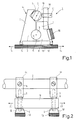
- the linear motor 1 shown in FIGS. 1 and 2 is movable as a unit along a rail 3, for. B. at a speed of 1 cm / sec.
- Two clamping devices 4a and 4b act on the rail 3.
- Each of the clamping devices consists of a bracket 5 with two bracket arms 6, 7 and a base 8.
- the base 8 has a cross-sectional taper 10 in the region of an incision arch 11.
- Two feet 12 are provided on the base 8 on both sides of the incision sheet 11.
- the feet 12 are attached to a piezoelectric clamping actuator.
- This piezoelectric clamping actuator 13 can be elongated in the direction of arrows 14, and because of its electrically excited elongation, the feet 12 can be pressed apart.
- the bracket arm 6 has a V-shaped pressure bearing 15 and the bracket 7 has a point-shaped pressure bearing 16.
- the punctiform pressure bearing 16 is formed by a clamping screw 17 which is rotatably mounted in a shoulder 18 of the bracket 7 and can be delivered in the direction of the rail 3.
- the two clamping devices 4a and 4b are connected by means of a piezoelectric feed actuator 19 which can be elongated in the direction of the arrows 20.
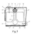
- the piezoelectric linear motor according to FIG. 3 is similar to that according to FIGS. 1 and 2, and it too can be in the caterpillar track move along the track 3. Only one of the clamping devices 4c is shown.
- the clamping device 4c again consists of two bracket arms 26, 27, which are connected via a base 28. Between the bracket arms 26 and 27 there is an incision 29 which reduces the cross section of the base 28 in the region 30.
- the somewhat wider feet 31, 32 of the base are connected to the piezoelectric clamping actuator 13. Both clamping devices of this motor are connected via a piezoelectric feed actuator 19, as in the motor according to FIGS. 1 and 2.
- Both free ends of the bracket arms 26 and 27 are provided with V-shaped bearing pits 33, 34 which can be set against the rail 3. Furthermore, a pressure piece 35 is provided, which is attached to a spring clip 36. One end of this spring clip 36 is fixed in the area of the base 28 by means of a screw 37 on the base 28. The other free end carries an adjusting screw 38 which can be rotated in and out to adjust the height of the free end relative to the bracket arm 26 into which it is screwed. The pressure of the pressure piece against the rail can be increased by tightening the screws.
- Both linear motors work in the same way.
- a clamping device for example the clamping device 4a in FIG. 2, is excited by elongation of the piezoelectric clamping actuator 13 and pressed against the rail 3.
- the clamping actuator 13 of the clamping device 4b is not energized, and the clamping bracket 5 releases the rail 3.
- the feed actuator 19 is excited.
- the clamping device 4b moves away due to its elongation by a few ⁇ m from the clamping device 4a.
- the rail is clamped in the region of the clamping device 4b by exciting the clamping actuator 13 of the clamping device 4b.
- clamping actuator 13 of the clamping device 4a is de-energized and the clamping device 4a releases the rail. If the feed actuator 19 is now also de-energized, it contracts. It then pushes the clamping device 4a behind the clamping device 4b by the amount of contraction in the caterpillar track.
- the actuators 13 and 19 are preferably designed as multi-layer actuators, with metal layers as electrodes being located between the piezoelectric ceramic plates. As a result, a voltage of typically 10V to 20V is sufficient to excite them and thus to operate the linear motor.
- FIG. 4 and 5 another embodiment of the linear motor 101 is shown, which can move along the rail.
- Clamping devices 104a and 104b surround the rail 103.
- Each of the clamping devices 104a and 104b consists of a mechanically rigid yoke 105, on the lower end of which a clamping jaw 106 is fastened with the aid of two screws 107.
- Three metallic connection lugs 109 make electrical contact with the electrode connections located on the bending actuator 108.
- the electrical connections 111 can e.g. B. are formed by soldering lead wires 110 to the metal tabs 111 in contact with the connecting tabs 109.
- a ceramic disk 112 is fastened to the bending actuator 108, for example by adhesive bonding, which bears against the rail 103 of the piezoelectric linear motor 101.
- the rail 103 lies in a V-shaped or triangular recess 114 in the yoke 105 and is thus guided through a three-point support.
- a further clamping jaw 115 is provided on the yoke 105, which can clamp a feed actuator 117 at one end each with two screws 116 when they are tightened.
- Each of the clamping devices 104a and 104b clamps one of the ends 117a of the feed actuator 117.
- the mode of operation of the linear motor 101 corresponds to that of the linear motor 1 according to FIGS. 1 to 3, with the exception that the clamping on the rail 103 does not take place by means of a clamping bracket, but rather by means of the bending, elongated bending actuator 108.
- the bending actuator 108 is bent against the rail 103, and to release the clamping device, the bending actuator 108 is bent away from the rail.
- the mechanical deflection at the free end 108b of the bending actuator can be approximately 100 ⁇ m to 200 ⁇ m with an electrical voltage of 15 V to 30 V.
- the bending actuator 108 of the clamping device 104a is bent against the rail 103.
- the desired contact pressure can be preselected by the electrical pre-tension.
- the bending actuator 108 of the clamping device 104b is bent away from the rail.
- the low contact pressure is preselected electrically. If the feed actuator 117 is now excited, then the clamping device 104b moves away by the elongation path of the feed actuator 117. After the lengthening of the feed actuator 117, the bending actuator 108 of the clamping device is bent onto the rail 103, which now also causes the clamping device 104b on the rail clamped.
- the bending actuator 108 of the clamping device 104b is now bent away from the rail 103, and the clamping device 104a is thus freely movable. If the feed actuator 117 is now de-energized and thereby shortened, then the clamping device 104a follows the clamping device 104b. By continuously repeating these excitation, de-excitation and re-excitation processes, the linear motor 101 travels along the rail 103.
- An advantage of the embodiment according to FIGS. 4 and 5 is that the manufacturing tolerances of the rail 103 are of little importance.
- the device is suitable, for example, for moving an optical unit in a CD player.
- the control is simple and can be made very small.
Landscapes
- General Electrical Machinery Utilizing Piezoelectricity, Electrostriction Or Magnetostriction (AREA)
Applications Claiming Priority (2)
| Application Number | Priority Date | Filing Date | Title |
|---|---|---|---|
| DE3825587A DE3825587A1 (de) | 1988-07-28 | 1988-07-28 | Piezoelektrischer linearmotor |
| DE3825587 | 1988-07-28 |
Publications (2)
| Publication Number | Publication Date |
|---|---|
| EP0352858A2 true EP0352858A2 (fr) | 1990-01-31 |
| EP0352858A3 EP0352858A3 (fr) | 1990-12-27 |
Family
ID=6359712
Family Applications (1)
| Application Number | Title | Priority Date | Filing Date |
|---|---|---|---|
| EP19890201930 Withdrawn EP0352858A3 (fr) | 1988-07-28 | 1989-07-24 | Moteur linéaire piézo-électrique |
Country Status (3)
| Country | Link |
|---|---|
| EP (1) | EP0352858A3 (fr) |
| JP (1) | JPH0287982A (fr) |
| DE (1) | DE3825587A1 (fr) |
Cited By (2)
| Publication number | Priority date | Publication date | Assignee | Title |
|---|---|---|---|---|
| EP0873963A1 (fr) * | 1997-04-25 | 1998-10-28 | Inventio Ag | Entraínement linéaire pour un dispositif de transport |
| WO2001015308A1 (fr) * | 1999-08-23 | 2001-03-01 | Rockwell Science Center, Llc | Moteur lineaire piezo-electrique de poussee et de traction a force elevee |
Families Citing this family (10)
| Publication number | Priority date | Publication date | Assignee | Title |
|---|---|---|---|---|
| DE4410248C1 (de) * | 1994-03-24 | 1995-07-13 | Fraunhofer Ges Forschung | Piezoelektrische Antriebsvorrichtung |
| DE29520885U1 (de) * | 1995-05-11 | 1996-04-18 | Forschungszentrum Karlsruhe GmbH, 76133 Karlsruhe | Mikromechanischer Aktor |
| DE19540439C2 (de) | 1995-10-30 | 1999-04-22 | Schwind Gmbh & Co Kg Herbert | Vorrichtung zur Hornhautchirurgie |
| US7166117B2 (en) | 1996-02-07 | 2007-01-23 | Hellenkamp Johann F | Automatic surgical device and control assembly for cutting a cornea |
| DE19639606C1 (de) * | 1996-09-26 | 1998-01-22 | Fraunhofer Ges Forschung | Greifersystem zum Handhaben und Feinpositionieren von Gegenständen sowie ein Verfahren zum Feinpositionieren |
| DE19746038C2 (de) * | 1996-10-18 | 1999-07-01 | Schwind Gmbh & Co Kg Herbert | Vorrichtung zur Hornhautchirurgie |
| DE19710601C2 (de) * | 1997-03-14 | 1999-05-20 | Univ Magdeburg Tech | Bewegungsgenerator |
| DE19946820A1 (de) * | 1999-09-30 | 2001-05-10 | Viktor Dirks | Schwingungsantrieb |
| CN100486549C (zh) | 2003-04-07 | 2009-05-13 | 泰克诺拉斯眼科系统有限公司 | 微型角膜刀的连杆驱动系统 |
| CN105619428B (zh) * | 2016-03-04 | 2018-09-11 | 武汉理工大学 | 一种面向光纤相位对准操作的复合式微夹钳 |
Family Cites Families (4)
| Publication number | Priority date | Publication date | Assignee | Title |
|---|---|---|---|---|
| GB1261523A (en) * | 1968-10-02 | 1972-01-26 | Secr Defence | Linear stepper motors |
| DE1933205A1 (de) * | 1969-06-26 | 1971-01-07 | Siemens Ag | Mikroschritt-Motor |
| JPS6162370A (ja) * | 1984-08-31 | 1986-03-31 | Tokyo Juki Ind Co Ltd | ピエゾモ−タ |
| US4736131A (en) * | 1985-07-30 | 1988-04-05 | Nec Corporation | Linear motor driving device |
-
1988
- 1988-07-28 DE DE3825587A patent/DE3825587A1/de not_active Ceased
-
1989
- 1989-07-24 EP EP19890201930 patent/EP0352858A3/fr not_active Withdrawn
- 1989-07-25 JP JP1190696A patent/JPH0287982A/ja active Pending
Cited By (4)
| Publication number | Priority date | Publication date | Assignee | Title |
|---|---|---|---|---|
| EP0873963A1 (fr) * | 1997-04-25 | 1998-10-28 | Inventio Ag | Entraínement linéaire pour un dispositif de transport |
| US6053287A (en) * | 1997-04-25 | 2000-04-25 | Invento Ag | Linear drive for transportation equipment |
| WO2001015308A1 (fr) * | 1999-08-23 | 2001-03-01 | Rockwell Science Center, Llc | Moteur lineaire piezo-electrique de poussee et de traction a force elevee |
| US6246157B1 (en) | 1999-08-23 | 2001-06-12 | Rockwell Science Center Llc | Push-pull high force piezoelectric linear motor |
Also Published As
| Publication number | Publication date |
|---|---|
| EP0352858A3 (fr) | 1990-12-27 |
| DE3825587A1 (de) | 1990-02-01 |
| JPH0287982A (ja) | 1990-03-28 |
Similar Documents
| Publication | Publication Date | Title |
|---|---|---|
| EP0352858A2 (fr) | Moteur linéaire piézo-électrique | |
| EP1090431A1 (fr) | Actionneur piezoelectrique | |
| EP1267478A2 (fr) | Dispositif d'entraínement linéaire comportant un groupe d'actionneurs piézocéramiques multicouche et sa méthode de fonctionnement | |
| DE102009012626A1 (de) | Linearführung mit Bremseinrichtung | |
| DE102013107154A1 (de) | Antriebsvorrichtung | |
| WO2005027235A1 (fr) | Actionneur piezoelectrique a etablissement de contact | |
| EP1384272B1 (fr) | Systeme de contact supplementaire pour composant electrique et composant piezo-electrique a structure multicouche | |
| DE19981030B4 (de) | Vorschubeinheit zum Bewegen von Bauteilen | |
| DE68927500T2 (de) | Elektrische Verformungsvorrichtung | |
| EP1405372A2 (fr) | Systeme de contact supplementaire pour un composant electrique et composant piezo-electrique a structure multicouche | |
| DE10112588C1 (de) | Piezoaktor sowie Verfahren zur Herstellung eines Piezoaktors | |
| DE19704389A1 (de) | Aktor aus Einzelelementen | |
| WO2012080381A1 (fr) | Piézoactionneur | |
| DE19905726C2 (de) | Verfahren zum Einstellen der mechanischen Vorspannung piezoelektrischer Antriebselemente | |
| DE4410248C1 (de) | Piezoelektrische Antriebsvorrichtung | |
| WO2010076116A1 (fr) | Activateur empilé piézoélectrique | |
| WO1992002962A1 (fr) | Dispositif de serrage pour corps magnetostrictif | |
| DE102005010073B4 (de) | Elektromechanisches Präzisions-Antriebssystem | |
| WO2007045525A1 (fr) | Moteur lineaire a ultrasons | |
| DE102011117778B3 (de) | Bauteil mit veränderbarer Nachgiebigkeit und Federkonstante bei einer Biegung | |
| DE19859024A1 (de) | Antriebsvorrichtung | |
| EP1724849A2 (fr) | Élément piézo-électrique | |
| EP0576707A1 (fr) | Empilement pour mouvement de translation et procédé de sa production | |
| DE10150126B4 (de) | Haltevorrichtung für einen Gegenstand sowie Haltesystem | |
| DE102004005943A1 (de) | Elektrisches Bauteil mit einem elekrisch leitfähigen Draht und Verwendung des Bauteils |
Legal Events
| Date | Code | Title | Description |
|---|---|---|---|
| PUAI | Public reference made under article 153(3) epc to a published international application that has entered the european phase |
Free format text: ORIGINAL CODE: 0009012 |
|
| AK | Designated contracting states |
Kind code of ref document: A2 Designated state(s): DE FR GB |
|
| PUAL | Search report despatched |
Free format text: ORIGINAL CODE: 0009013 |
|
| AK | Designated contracting states |
Kind code of ref document: A3 Designated state(s): DE FR GB |
|
| 17P | Request for examination filed |
Effective date: 19910620 |
|
| STAA | Information on the status of an ep patent application or granted ep patent |
Free format text: STATUS: THE APPLICATION IS DEEMED TO BE WITHDRAWN |
|
| 18D | Application deemed to be withdrawn |
Effective date: 19930202 |