EP0352883A2 - Appareil et méthode de contrôle de la topologie d'un réseau - Google Patents
Appareil et méthode de contrôle de la topologie d'un réseau Download PDFInfo
- Publication number
- EP0352883A2 EP0352883A2 EP89304502A EP89304502A EP0352883A2 EP 0352883 A2 EP0352883 A2 EP 0352883A2 EP 89304502 A EP89304502 A EP 89304502A EP 89304502 A EP89304502 A EP 89304502A EP 0352883 A2 EP0352883 A2 EP 0352883A2
- Authority
- EP
- European Patent Office
- Prior art keywords
- station
- connection type
- connection
- stations
- type
- Prior art date
- Legal status (The legal status is an assumption and is not a legal conclusion. Google has not performed a legal analysis and makes no representation as to the accuracy of the status listed.)
- Granted
Links
Images


Classifications
-
- H—ELECTRICITY
- H04—ELECTRIC COMMUNICATION TECHNIQUE
- H04L—TRANSMISSION OF DIGITAL INFORMATION, e.g. TELEGRAPHIC COMMUNICATION
- H04L41/00—Arrangements for maintenance, administration or management of data switching networks, e.g. of packet switching networks
- H04L41/12—Discovery or management of network topologies
-
- H—ELECTRICITY
- H04—ELECTRIC COMMUNICATION TECHNIQUE
- H04L—TRANSMISSION OF DIGITAL INFORMATION, e.g. TELEGRAPHIC COMMUNICATION
- H04L12/00—Data switching networks
- H04L12/28—Data switching networks characterised by path configuration, e.g. LAN [Local Area Networks] or WAN [Wide Area Networks]
- H04L12/42—Loop networks
Definitions
- This invention relates to computer local area networks and in particular to a method and apparatus for enforcing valid network topologies.
- LANs interconnect a collection of stations for the purpose of exchanging information over a communications channel.
- LANs that cover extended distances and/or are based on fiber optics may configure a "ring" from a number of individual point to point physical connections between the stations comprising the network to form the communication channel.
- rings are exemplified by the FDDI (Fiber Distributed Data Interface) proposed by American National Standards Institute (ANSI) and IEEE standard 802.5-1985 "American National Standard for Token Ring Access Method," ANSI X3.139-1987, “Fiber Distributed Data Interface Media Access Control (MAC),” and ANSI X3.148-1988, "Fiber Distributed Data Interface Physical Layer Protocol (PHY).”
- Double loop rings are often configured rather than single loop rings.
- each ring in fact consists of a primary and a secondary ring.
- the stations, or nodes, making up the LAN may be combinations of single attachment stations (SAS) 10 of Fig. 1A, having a single physical attachment point (which includes the media, or the hardware comprising the communication link to an adjacent station), dual attachment stations (DAS) 12 of Fig. 1B, having two attachment points, wire concentrators (WC) 14 of Fig. 1C, having many attachment points, and combination DAS/WC stations 16 of Fig. 1D having two attachment points on the DAS side and several attachment points on the WC side and internal connections (not shown) between the WC and the DAS.
- SAS single attachment stations
- DAS dual attachment stations
- WC wire concentrators
- WC wire concentrators
- WC wire concentrators
- PC Physical Connection
- the communications channel may be configured as a physical loop with "trees" branching to stations not on the ring.
- the two rings are often formed into one ring, which will be called the primary ring.
- LAN 20 of Fig. 2 An example of a LAN configured as a ring of trees of the above mentioned station types is shown by LAN 20 of Fig. 2.
- the two physical links of each PC are connected to other PC's to provide two rings, a primary ring 22 and a secondary ring 24.
- Use of two rings ensures tolerance to station or channel failure as explained by Rom et al. in "A Reconfiguration Algorithm for a Double-Loop Token-Ring Local Area Network," IEEE Transactions on Computers, Vol 37, No. 2, February 1988.
- the network automatically reconfigures to eliminate the failed element and resume operation, as shown by LAN 50 of Fig. 3 where loopbacks 54 and 58 "heal" the ring and permit continued operation by the attached stations.
- LAN stations may conform to the reference model Open Systems Interconnection (OSI) which calls for a layered station organization as proposed by the International Standards Organization and described by A.S. Tanenbaum in “Computer Networks,” Prentice Hall, Inc., 1981, pages 16-21.
- OSI Open Systems Interconnection
- Each station contains a Physical (PHY), Data Link, Network, Transport, Session, Presentation, and Application layer.
- PHY provides electrical and/or optical connections, encodes and decodes the signals for all higher layers, and essentially supports a communication channel from one station to another and transmits and receives data to and from the PHY of a connected station.
- the data link layer contains Media Access Control (MAC) which controls access to the communications media or channel, and the transmission of data packets to and receipt of data packets from the MACs of other stations using individual (MAC) addresses.
- a data packet is a sequence of data bits on the communications channel which contain the information to be passed from station to station.
- Connection management controls the internal interconnection of the PHY and MAC entities within a station, the external configuration (topology), and establishes the logical connection between adjacent stations.
- a DAS is a station, which when its connections type “A” and “B” are connected to the connections type “A” and “B” of another DAS, provides a double loop ring, as shown in Fig. 2.
- the primary and secondary rings 22 and 24 comprise each of the double loops.
- a connection type "M” on a WC or DAS/WC forms a "tree” configuration when attached to the connection type "A” of another station, as shown in Fig. 4. Even though a connection type "M” has two physical links, each link forms a part of a single ring.
- a DAS/WC station forms a double loop ring with its connections type "A” and “B” and the branches of a tree with its connections type "M.”
- the SAS connects to each branch as a "leaf" of a tree.
- stations are physically connected to each other, but not logically connected, because although the stations are wired together, the internal configuration of the stations prevents data packets from one station on one ring from being received by another station which is not configured on that ring.
- stations are considered to be "PHY" connected if and only if they are spanned by a physical cable path where all physical connections in the path are considered usable for data transfer.
- Stations are logically connected if and only if they can exchange MAC protocol data units (PDUs).
- PDUs MAC protocol data units
- DAS and DAS/WC stations are intended to form double loop rings when attached to other DAS and DAS/WC stations via their connections type "A" and "B.”
- Current Station Management protocols as described by ANSI subcommittee X3T9.5, "FDDI Station Management (SMT)" in document no. X3T9.5/84-49, 1 August, 1987, do not globally identify a primary or secondary ring and can result in topologies, such as the twisted ring topology of LAN 20 of Fig. 2, if the stations are inadvertently connected incorrectly.
- Stations connected to DAS/WC stations 28 and 32 are connected to the communications channel forming primary ring 22, but station 36 considers ring 24 to be the primary ring. Stations attached to DAS/WC 36 are therefore unable to communicate, i.e., are not logically connected with stations attached to DAS/WCs 28 and 32 which are configured on the primary ring.
- WC or the WC portions of DAS/WC stations are commonly configured as trees, where a connection type "M" of a WC or DAS/WC connects to a connection type "A" of a DAS or DAS/WC. Stations connected as trees do not form double loop rings. Rather, a single ring is intended.
- LAN 100 of Fig. 4 is a tree comprising two DAS/WC stations which illustrates another illegal topology that can result from improperly connecting stations.
- SAS 110 is physically connected but not logically connected to the remaining SAS nodes.
- the spanning tree algorithm which identifies and corrects (eliminates) illegal topologies, runs in the network layer, and is very complicated, but allows all connection types to be the same and still results in all possible topologies as legal by configuring all networks as trees.
- Implementation requires too much information to be exchanged by stations to allow the algorithm to run in the MAC layer or Physical layer. In traditional network layer solutions, stations must exchange information with other non-adjacent stations which results in a complex distributed "N-party" algorithm.
- a local area network having a self-controlling topology comprising a plurality of stations including single attachment stations (SAS), dual attachment stations (DAS), wire concentrator stations (WC), and WC/DAS stations; a plurality of duplex point to point physical connections connecting the stations; means for exchanging station connection information over the physical connections between immediately adjacent stations using PHY layer signaling; means for determining, in each of the stations by analysis of the exchanged information, the validity of all connections to each of the immediately adjacent stations represents according to a predetermined connection validation list; and means for indicating invalid connections according to the validation list. Means is provided for rejecting invalid connections, or in some cases, means is provided for reconfiguring the network topology to create a valid topology.
- LAN 150 of Fig. 5 having a self controlling topology, is shown by way of example and not as a limitation as comprising combinations of SAS stations 1541-1548, WC stations, DAS stations and DAS/WC stations 1561-1564 interconnected by duplex, point to point physical connections such as 160.
- This set of stations is necessary and sufficient to configure a double loop ring of trees topology and comprises a set of valid or "legal" station types.
- Other types of stations such as SAS/WC combination stations are not shown as they do not add new topology or behaviors over the given set.
- the DAS and WC stations are shown as combined as DAS/WC stations 1561-1564. Although the two station types are combined into a single station, their individual functions remain the same whether applied singly or in combination.
- any subset of the DAS/WC is considered a valid station type.
- stations 12 and 14 are subsets of station 16.
- a station type is defined by its connection types and internal behavior. Connection types are specified for the purposes of topology control. Each station type of. Figs. 1A-1D has a letter assigned to the physical connection type associated with the station.
- SAS 10 has a connection type "S”
- WC 14 has at least one connection type "M”
- DAS 12 has two connections, types "A” and "B”
- DAS/WC 16 has the same "A,” "B,” and "M” connection types as the individual DAS and WC stations.
- Connections type “A” and “B” are intended to form double loop rings when connected to other connections type “A” and “B” of other stations.
- DAS station 16 has connections type “A” and “B” for this purpose.
- Connections type “M” and “S” are intended to form a single logical ring on a physical branching topology of a tree.
- Concentrators have multiple connections type “M” for this purpose, and the connection type “S” and its SAS is considered to be a "leaf” on a tree.
- a concentrator may also be a node in a tree by use of a connection type "M” of one station to a connection type "A” of a second station.
- connection type "B” may be used to connect to the node in a tree, but both a connection type "A” and a connection type “B” may not be used.
- a tree may have one data path up or down, but not two. Therefore the formation of trees is restricted to connections type "A” in the preferred embodiment.
- a tree is the connection of a connection type "M” of one station to a connection type "A” of another station. This is a separate, non-conflicting use of a connection type "A” in a WC, where the connection type "A” is not intended to attach to the double loop ring.
- a set of rules in the form of a validation list must be enforced concerning the connection types.
- the present invention provides control of a topology such that all connections which are offered by a user or installer for the LAN will have predictable and intuitively expected results, that is, adding a cable should never cause a reduction in the number of stations which can communicate, or the set of stations which communicate should never change because a distant station was powered off and then on.
- a topology which has this property is loosely defined as a "legal" topology.
- LAN 150 comprises only 4 DAS/WC stations interconnected with each other and SAS stations to make a double loop ring LAN, any number of SAS, DAS, WC and DAS/WC stations may be interconnected providing the interconnections are valid according to the connection matrix.
- Application of the connection matrix to a topology results, among other things, in the global identification and enforcement of a primary ring.
- connection type "A” is defined to have the primary ring output.
- a requirement of a topology is to have a globally identified primary ring. This convention serves to resolve the symmetry in the dual ring.
- a connection type "B” is the PHY in a DAS that attaches to the primary ring input when attaching to the dual ring.
- Other conventions, such as where connections type "A” are the primary ring input may also be defined and enforced according to the invention with equal ease. It is a characteristic of connections type "A” and “B” that they form a double loop ring when connected to the connections type "A” and "B” of other DAS or DAS/WC stations.
- connection types "A” and "B” in a DAS/WC are required to be adjacent to each other within the station, as will be discussed below.
- a connection type “S” is the PHY in a SAS.
- a connection type “M” is the PHY in a WC or DAS/WC that serves as a master to a connected station.
- connection type "M” It is the characteristic of a connection type "M” to form a tree when connected to a connection type "A” or “S” of another station, but not both a connection type "A” and a connection type “B” otherwise a master/slave loop may exist, as will be discussed in more detail below.
- a tree is a single loop attachment rather than a double loop attachment to another station.
- connection types of the stations of Figs. 1A-1D correspond to the column and row labels "A B M S" of the connection matrix.
- communications channel 160 of Fig. 5 one end is connected to a connection type "B" of DAS/WC station 1561 and the other end is connected to a connection type "A” of DAS/WC station 1562.
- connection matrix shows that an "S” to “M” or “M” to “S” connection is valid. Note that an “S” to “S” connection is also valid, but results in a network of only two SASs.
- connection matrix is symmetric, that is, a connection is valid or invalid regardless of which station is called "MY END.”
- the exception is the "A” to "M” connection which must follow the "RULE.”
- My A may accept as valid a connection to an "M” if and only if "My M” or “My B” does not connect to an "A.”
- the rule prevents the formation of master/slave loops when stations are connected in a tree, as shown in Fig. 4.
- connection matrix to LAN topologies requires that the LAN stations comprise only the four specified types: SAS, DAS, WC, and DAS/WC (including any subset of a DAS/WC), and will result in LAN configuration of the stations as a double loop ring of trees.
- a legal topology was defined loosely by the expectations of a LAN user.
- a legal topology is now strictly defined to have the following necessary properties:
- a "legal" topology comprises only valid connections according to the connection matrix and has the property that all stations physically connected by the LAN are also logically connected to the LAN, that is, each station will be able to autoconfigure to send and receive MAC sublayer messages, also called frames or MAC PDUs, to and from all other stations connected to the ring.
- Fig. 2 is an example of a conventional LAN having an "illegal" topology, that is, all stations are physically connected but some stations are not logically connected and thus from a user perspective, have invalid connections.
- the primary ring is not unique or globally identified, and the resulting configuration is a "twisted loop.”
- DAS/WC stations 28, 32 and 36 and their attached SASs (not shown) are physically connected and form a dual ring, 22 and 24, but the SASs attached to DAS/WC stations 28 and 32 are connected to primary ring 22, while the SASs of DAS/WC station 36 are connected to secondary ring 24 and they are not logically connected to the stations on the primary ring.
- a system manager may command a station to autoconfigure to make a logical connection happen or not happen.
- the primary ring can be globally identified and enforced to prevent inadvertently mis-connecting stations on either ring.
- connection type "A" of station 36 to the connection type "A” of station 28 is identified as invalid and the cause of the non-unique primary ring.
- the "B" connection of station 32 to the "B” connection of station 36 is also an invalid connection according to the connection matrix.
- LAN 100 of Fig. 4 is another example of an "illegal" topology.
- WC stations 114 and 118 are connected as for a tree, but with too many connections such that a physical (master/slave) loop occurs resulting in primary ring 106 and an unintended ring 108.
- Stations 114 and 118 are examples of WC stations that each have a connection type "A" so that the WC may form a master/slave tree configuration with another station.
- connection type A may also be considered to be a DAS/WC with an unused connection type "B."
- SAS 110 is physically connected to station 118, but is logically connected to unintended ring 108, whereas the remaining SASs are logically connected to primary ring 106 and therefore cannot communicate with SAS 110.
- connection matrix to LANs having stations limited to the four station types of Fig. 1 with their four connection types, obviates the need to consider complex station interconnections and allows simple solutions to LAN topology.
- LAN topology control is achieved using multiple instances of distributed two-party algorithms that base decisions only on the exchange of local information.
- the global topology may be spanned by a single primary ring, and other previously discussed "legality" requirements are met.
- PCM Physical Connection Management
- connection matrix In operation, application of the rules of the connection matrix to automatically control the topology of a LAN comprising combinations of the stations of Fig. 1 arranged in a ring of trees configuration is implemented in SCM.
- a method for automatic controlling of LAN topology which begins during power up of a station by exchanging station connection information over the physical connections between immediately adjacent stations using messages that are easily transmitted using only PHY layer signaling.
- PHY layer signaling provides the advantage that individual MAC addresses are not required.
- the PHY of each station signals its connection type to an adjacent connected station using Physical layer symbols well-known in the art.
- the adjacent station accepts connections from other stations identified by only a limited set of Physical layer symbols, depending on its own connection type.
- Physical layer symbols comprise combinations of line states.
- a line state is a sequence of more than 15 symbols.
- a master line state (MLS) is a series of alternating HALT and QUIET symbols.
- a halt line state (HLS) is a stream of HALT symbols.
- a quiet line state (QLS) is a series of QUIET line symbols.
- An idle line state (ILS) is a stream of IDLE line symbols, and an idle quiet line state (IQLS) is an alternating series of IDLE and QUIET symbols.
- connection type line state table The line state messages sent or accepted by each connection type are shown in the connection type line state table, below. CONNECTION TYPE SENDS ACCEPTS A IQLS MLS, HLS B HLS IQLS M MLS HLS, IQLS S HLS HLS, MLS
- connection type has a specified behavior, and this set of connection types allows construction of the most desirable topologies for the LAN.
- the symbols sent and accepted by the connection types of the line state table correspond to the valid connections permitted by the connection matrix, as will be described in more detail below.
- the signaling method of the line state table for adjacent stations is one of many effective methods. Another method of signaling would be to send unique combinations of multiple line state sequences to indicate each connection type. Encoding could be used where one line state could represent a "1" and another line state could represent a "0,” and a series of line states could be sent to indicate multiple bits of information. ILS followed by MLS could be the "1" and ILS followed by HLS could be "0.” Unique combinations of "bits" could represent each connection type. The same messages may also be sent in MAC PDUs.
- connection type "M” 168 is connected to a connection type "A" 172 of station 1564.
- Connection type “M” 168 sends an "M message” to the immediately adjacent station to which it is connected, i.e., connection type "A” 172.
- Connection type "A” 172 according to the line state table, sends an "A message” and accepts an "M message.”
- Connection type "M” 168 accepts the "A message.” Therefore, the connection of connection type "M” 168 to connection type "A” 172 is a valid connection.
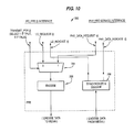
- Data Link layer 254 and PHY 258 are schematically represented as part of a general model of LAN station 250 of Fig. 7 insofar as they apply to implementation of the connection matrix to automatically control the network topology.
- Station 250 contains n connection ports or physical attachment points, each having a specified connection type, and each port is represented by i, where i is an integer from 1 to n. Values of i greater than n represent internal MACs in station 250.
- SCM 262 contains the hardware to implement the connection matrix for the station.
- the SCM is specific to the station type, and its operation for each of the allowable station types, i.e., DAS, DAS/WC, WC, and SAS, will be discussed in greater detail below.
- SCM 262 contains a number n of station configuration submodules (SCS) 2641-264 n , one for each connection, or media attachment connector of the station, and each SCS is configured to function as a specific connection type having behavior as specified for such connection type.
- SCS station configuration submodules
- Each SCS connects to a corresponding physical connection module or manager (PCM) 2681-268 n , thus establishing the topological behavior of each PHY attachment point.
- PCM physical connection module or manager
- the PCM protocol establishes a shared state with another connected PCM which includes a connection status (either connected or disconnected), and a connection type (A, B, M, or S).
- Flowchart 300 of Fig. 8, to be discussed below, shows the protocol executed by each PCM to exchange connection types, establish a connection status, and accept, reject, or reconfigure connections.
- the PCM protocols are multiple, concurrent processes which exchange information via defined interfaces.
- the interfaces between the boxes, or entities, in general station 250 of Fig. 7 are given names, and each interface may comprise one or more named signals. If the interface is a single signal, then the interface has the name of the signal. Signals may be of two types, either a control signal which means "do something," or a status variable passing information. Interfaces are shown drawn with single lines, although the signals may comprise one or more parallel bits on a multiline bus.
- SC_PCM(i) passes the necessary connection data back and forth between the SCS and the respective PCM.
- SC_PCM(i) provides a control directive to either connect or disconnect with the adjacent station, a signal PC_type(i), which signifies whether the connection to an adjacent station is determined by SCM to be valid or invalid, i.e., OK and Not_OK, and a signal MY_type(i) which identifies to PCM the respective connection as a connection type "A,” "B,” “M,” or "S.”
- SC_PCM(i) also returns a status signal N_type(i) from the PCM to the SCS, which is the adjacent station (neighbor) type.
- N_type(i) is either "A,” “B,” “M,” “S,” or null, where null means “don't know yet.”
- SCSs 2641- 264 n pass signal MODE(i), which has values of Tree, Not_tree, and Root, and the signal Loop_warning, which has values of true and false, among themselves for the purpose of sharing local topology information within the SCM.
- Signal MOVE(i) provides a true or false input to data path switch element i.
- Loop_warning is a signal used for reconfiguring the network topology when a connection between a connection type "M” and a connection type "A" of an adjacent station is determined to be invalid.
- Signal "Policy,” having values of disconnect and move, is input to station 250 of Fig. 7 by a higher layer authority, designer, or manager, shown as local management interface 280, for use in resolution of detected faults in a ring of trees.
- the options for the manager are to instruct SCM to disconnect invalid tree connections or to reconfigure the invalid tree connections, where possible, as discussed below.
- the response to an invalid connection could also be to signal the connection as invalid to local management interface 280, but not disconnect the invalid connection.
- Each PCM 2681-268 n controls a data path switch (DPS) element i of DPS 278, where i is 1 to n+1.
- DPS elements 1 to n have physical attachment points to external cables (the communications media).
- DPS element n+1 connects internally to the station primary loop MAC and has no external connection point.
- DPS element n+2, located between elements n and n-1, could be used to connect a MAC to a secondary ring.
- Switch 360 of Fig. 9A is an example of a DPS element which is controlled by signals MOVE(i) and DPS_enable, and which provides interface PC_PPE(i) to a respective physical protocol entity (PPE) 2721-272 n .
- SCM thus controls the externally viewed topology and the function of the PPE.
- MOVE(i) and DPS_enable(i) are either true or false and switch the respective PCM into or out of the primary ring.
- DPDT switch 366 is in the bypass position
- DPDT switch 368 sets DPDT switch 368 to the bypass position thereby reordering the attachment points.
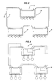
- DPS 278 of Fig. 7 is shown in greater detail by DPS 370 of Fig. 9B.
- Each DPS element 3721-372 N+1 is a DPS element similar to DPS 360 of Fig. 9A.
- DPS 370 is a correct configuration of a DPS of a reconfigurable DAS/WC station, shown generally by station 250 of Fig. 7.
- DPS elements 3721-372 N-2 are ports for connection points to the station as connections type "M.”
- DPS elements 372 N-1 and 372 N are connection points for a connection type "A" and a connection type "B,” respectively. There may only be one connection type "A” and one connection type "B” in any one station.
- DPS element 372 N+1 connects to the MAC for the primary ring.
- Each DPS element is connected on an internal ring 374 that passes through each DPS element twice, connecting to each DPDT switch as shown in Fig. 9A. Ring 374 may be one or more bits wide.
- DPS elements 3721 to 372 N+1 are identical, regardless of the connection type or internal station entity to which they connect. MOVE(i) for each DPS element greater than N-2 is set false, thus defining the internal topology of station 250. The order of DPS elements in a "legal" station however, is important. DPS elements for connections type "M" must be adjacent to one another on ring 374.
- DPS element 372 N+1 which connects to the station MAC for the primary ring, is connected between the DPS element 372 N-1 for the connection type "A" and DPS element 372 N-2 for the highest numbered connection type "M.”
- DPS element 372 N (the highest numbered DPS element having a connection point external to the station) is connected immediately adjacent to DPS element 372 N-1 for the connection type "A.”
- a DPS element for a MAC for a secondary ring would be connected between DPS element 372 N-1 for the connection type "A” and DPS element 372 N for the connection type "B.” All subsets of DPS 370 are also "legal" data path switches.
- Data flow within the DPS is from any of the connections type "M" (DPS elements 3721 to 372 N-2 ) to the DPS element for the primary ring MAC (DPS element 372 N+1 ) to the DPS element for the connection type "A” (DPS element 372 N-1 ) to the DPS element for the secondary ring MAC (not shown) and then to the DPS element for the connection type "B.”
- DPS elements 3721 to 372 N-2 Data flow within the DPS element for the connections type "M” (DPS elements 3721 to 372 N-2 ) to the DPS element for the primary ring MAC (DPS element 372 N+1 ) to the DPS element for the connection type "A” (DPS element 372 N-1 ) to the DPS element for the secondary ring MAC (not shown) and then to the DPS element for the connection type "B.”
- DPS element of DPS 370 is similar, the order of the elements on internal ring 374 governs proper operation of DPS 370.
- a DPS has the property that a connection type "M” can be moved from a position electrically located in terms of data flow between two connections type "M” to a position, electrically located in terms of data flow, most distant from the output of the connection type "A.”
- MOVE can be used to swap the roles of connections type "A” and B or move a MAC to or from a primary or secondary ring.
- Interface PC_PPE(i) comprises control signals Transmit_PDR(i) and LS_request(i).
- Transmit_PDR(i) is a true or false signal applied to multiplexer 394 of PPE 390 and determines whether signal LS_request(i) or PHY_data_request(i) is encoded by encoder 396 and passed to the media.
- Decoder 398 receives signals from the media and generates LS_indicate(i) and PHY_data_indicate(i).
- LS_request(i) is the line state message sent to the adjacent station, and comprises the prior mentioned line states QLS, HLS, MS, IQLS and ILS, or a combination of codes to signal connection type.
- PHY_data_request(i) is the data from the next PHY entity or from a higher layer of the station.
- Interface PC_PPE(i) also provides status signal LS_indicate(i), which is passed from a PPE to its respective PCM.
- LS_indicate(i) is the line state or message representing its connection type received from the adjacent station.
- Each PPE(i) has a PPE service interface, PPE_service(i), which passes protocol data units transmitted to or received from the media.
- PPE_service(i) which passes protocol data units transmitted to or received from the media.
- the ring is formed of point to point links, thus data is often passed directly between PPE's as determined by the DPS.
- Each station may have any number of MACs or no MACs.
- MAC 276 is connected to data path switch element n+1 because switch n+1 does not correspond to a physical attachment point for the media.
- PHY_data_indicate(i) is the name of the data received by the PPE from the media
- PHY_data_request(i) is the name of the data output to the PPE towards the media.
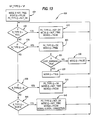
- Flowchart 300 of Fig. 8 shows the sequence of events performed by each PCM(i) to establish contact with a PCM(i) of an adjacent (connected neighbor or "OTHER END" as shown by the connection matrix) station and to validate the connection.
- Steps 304-324 of flowchart 300 show the steps performed by PCM(i) to exchange station connection information.
- LS_request(i) is set to QLS, Transmit_PDR(i) is set to false, and N_type(i) is set to null in step 304.
- DPS_enable(i) is always set equal to Transmit_PDR(i).
- timer TLA is reset to zero, step 308, and LS_request is sent to DLS, where DLS represents the set of line states or line state messages that identify the connection type, i.e., "A,” "B,” “M,” or “S,” of the PCM(i), which corresponds to MY_type(i), step 312.
- the duration of T b is chosen to be long enough to ensure that the adjacent station's PCM(i) has time to "see" the transmitted QLS, and thus ensuring the initialization of a new connection.
- N_type(i) is set to the connection type corresponding to the signaled line state, step 320.
- the convention used in step 320 indicates that N_type(i) is set equal to one of the values "A,” “B,” “M,” or “S” in the set DLS.
- MY_type is signaled until time period T dmin to ensure the connection type is received by the adjacent station. The duration of T dmin chosen to ensure that MY_type(i) is signaled long enough to be received by the adjacent station's PCM(i).
- N_type(i) to MY_type(i) connection is valid as decided in PCM according to the connection matrix
- PC_type(i) is OK
- Transmit_PDR(i) is set to true to permit PPE(i) 390 to send data or an idle line state, step 332, indicating that the connection is accepted locally at "MY" end. If the connection is not valid, PCM(i) continues to look at LS_indicate(i) in order to validate any corrected configuration.
- PCM(i) continues to monitor LS_indicate(i), step 336, and if LS_indicate(i) is not either an active or idle line state, the connection type for LS_indicate(i) is compared to the prior value of N_type(i), step 340. If the new and old connection types disagree, or no type is sent, the connection is again initialized starting at step 304.
- a method for determining, in each of the stations by analysis of exchanged information, the validity of the connection to each of the adjacent stations according to a predetermined validation list.
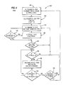
- step 404 Loop_warning is false and PC_type(i) is Not_ok. MODE(i) is Not_tree, and MOVE(i) is false, step 408. N_type(i) is ascertained by PCM. If N_type(i) is null in step 412, connection is not yet established or connection has been broken and processing returns to step 408 If N_type(i) is no longer null, then processing of the connection type can continue with step 416.
- a MY_type(i) of "A” may not connect to an N_type(i) of "A” or "S.” Therefore, if N_type(i) is "A,” PC_type is set to Not_ok (which controls concurrent PCM(i) processing as shown by flowchart 300 of Fig. 8), thereby rejecting the connection as invalid according to the connection matrix. Loop_warning is set to false, and an illegal connection is signaled in step 420. Local management interface 280 of Fig. 7 is informed of the illegal connection and sets an audio or visual alarm.
- N_type(i) is not "A,” processing continues with step 428 of Fig. 11.
- the connection matrix if MY_type(i) is "A” and N_type(i) is "B,” step 428, the connection is valid, PC_type(i) is set to OK, Loop_warning is set to false, step 432, and processing continues. If N_type(i) is neither "A,” “B,” nor “S,” N_type(i) is checked for type "M,” step 436. If N_type(i) is not "M,” the validation process is started over.
- MY_type "A” may keep a connection to an N_type “M” if and only if an "M” or a "B" of "MY” station does not connect to an N_type "A.”
- step 440 Application of the rule concerning trees begins in step 440, where the value of MODE(i) is checked for each SCS of "MY" station. If MODE(i) is not tree or root, then PC_type(i) is OK, step 444, and the connection is valid.
- MODE(i) is set to tree if MY_type(i) is "M” and it is connected to an N_type(i) of "A,” as shown in steps 616 and 620 of Fig. 13.
- MODE(i) is set to root in steps 520 and 524 of Fig. 12 if MY_type(i) is "B” and N_type(i) is "A.”
- step 448 If any MODE(i) of the SCM is root in Fig. 11, step 448, then the connection is invalid, and in step 452, PC_type(i) is set to Not_ok, which rejects the connection, Loop_warning is set to false, and an illegal connection is signaled to local management interface 280 of Fig. 7. Local management interface 280 indicates that the connection is invalid. If a MODE(1, . . ,n) in step 448 is tree, then the status of Policy, step 456, determines if the topology is to be reconfigured or whether the connection is to be considered invalid and rejected. Step 456 implements the policy set by the local station manager.
- step 452 of Fig. 11 is executed to set PC_type(i) to Not_ok, thereby rejecting the connection, set Loop_warning to false, and to signal an illegal connection to local management interface 280 of Fig. 7, which indicates that the connection is invalid. If the policy is to reconfigure the topology to correct the global topology problem caused by MY_type(i) connection type "A” to N_type(i) connection type "M,” then step 460 is executed.
- step 460 if less than two of the MODE(i) signals are tree, i.e., zero or one MY_type(i) connections type "M" are connected to an N_type(i) connection type "A,” then Loop_warning is set to true and PC_type(i) is set to OK and the connection is accepted.
- Loop_warning is set to true and PC_type(i) is set to OK and the connection is accepted.
- Application of Loop_warning to topology reconfiguration will be discussed below in regard to validation by a MY_type(i) connection type "M,” which is shown by flowchart 600 of Fig. 13 and is shown electrically in Figs. 14 and 15.
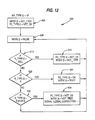
- N_type(i) is null in step 512, meaning N_type(i) has not yet been determined, PC_type(i) is set to Not_ok and MODE(i) is set to Not_tree, step 516, and the process is repeated beginning at step 508.
- N_type(i) is "A” in step 520, the connection is valid according to the connection matrix, PC_type(i) is set to OK, and MODE(i) is set to root for application of the rule by another MY_type(i) connection type A of "MY" station, as discussed above in relation to flowchart 400 of Fig. 11.
- N_type(i) is "B,” "M,” or “S” in step 530, the connection is not valid according to the connection matrix.
- PC_type(i) is set to Not_ok, which rejects the invalid connection
- MODE(i) is set to Not_tree
- an illegal connection in step 534 is signaled to local management interface 280 of Fig. 7 which identifies invalid connection.
- LAN 700 which is configured in the same manner and having the same connectivity problem as LAN 100 of Fig. 4, comprises two DAS/WC stations 704 and 708, each having a connection type "A" and a plurality of connections type "M.”
- the connection type "A" of each DAS/WC is connected to a connection type "M" of the adjacent DAS/WC.
- connection type "M" For simplicity, only the DPS of stations 704 and 708 are shown. No connections type "B" are needed for the example and are therefore not shown.
- Each DAS/WC contains four data path switch elements 7121-7124 and 7161-7164.
- Each data path switch element is controlled by signals DPS_enable(i) and MOVE(i) as shown by Fig. 9A.
- Each double pole double throw (DPDT) switch 366, 368 of data patch switch element 360 is shown positioned for a respective control signal for that switch of false.
- MOVE(i) and DPS_enable(i) control DPDT switch 366 through AND gate 364.
- connection type "A" 732 illustrates detection of an invalid connection of MY_type(i) A to an N_type(i) "M" because another connection type "M,” 736, of MY station is connected to a connection type "A.” Applying the rule to connection type "A" 740 of station 708 reveals the same type of invalid connection.
- the topology has successfully been reconfigured to place all four SASs 7201-7204 in primary loop 724 by electrically moving the connection type "M” data path switch element in the "OTHER” station to the location most distant, from the viewpoint of data flow, from the connection type "A" output of the "OTHER” station.
- the "location most distant” is the location where data from the connection type "M” data path switch element in the "OTHER” station must flow through all the connections type "M” of the "OTHER” station before reaching the connection type "A” output of the "OTHER” station.
- This reconfiguration function is applicable to a tree of arbitrary height.
- N_type(i) is "S” rather than "A” in step 636
- the connection is valid according to the connection matrix and PC_type(i) is set to OK, MODE(i) is set to Not_tree, and MOVE(i) is set to false in step 640.
- N_type(i) is "B” or "M” in step 644
- the connection is invalid according to the connection matrix and, in step 648, PC_type(i) is set to Not_ok, MODE(i) is set to Not_tree, MOVE(i) is set to false, the connection is rejected, and an illegal connection is signaled to local management interface 280 of Fig. 7.
- PCM(i) The validation of the connections to the last remaining connection type, "S," is performed by PCM(i) according to flowchart 800 of Fig. 16.
- PC_type(i) is set to Not_ok.
- MODE(i) is set to Not_tree and MOVE(i) is set to false.
- step 812 if N_type(i) is null, PC_type(i) is set to Not_ok in step 816 and validation starts over at step 808. If N_type(i) is "M” or "S” in step 820, the connection is valid according to the connection matrix. Therefore, PC_type(i) is set to OK. If N_type(i) is "A" or "B” in step 828, the connection is invalid and PC_type(i) is set to Not_ok.
- connection matrix is shown by way of example and not as a limitation as just one of many possible connection matrices that would be useful to implement a LAN topology autoconfiguration.
- “A” to "S” and “B” to “S” connection types were declared invalid for convenience of configuring networks as double loop topologies, not because of logical connectivity problems.
- “B” to “M” connections could be declared valid by the rule, while “A” to “M” connections could be invalid or either can be accepted in absence of the other, provided preference is given to one type of connection to provide that the topology will be deterministic.
Landscapes
- Engineering & Computer Science (AREA)
- Computer Networks & Wireless Communication (AREA)
- Signal Processing (AREA)
- Small-Scale Networks (AREA)
- Maintenance And Management Of Digital Transmission (AREA)
- Data Exchanges In Wide-Area Networks (AREA)
Applications Claiming Priority (2)
| Application Number | Priority Date | Filing Date | Title |
|---|---|---|---|
| US22403888A | 1988-07-25 | 1988-07-25 | |
| US224038 | 1988-07-25 |
Publications (3)
| Publication Number | Publication Date |
|---|---|
| EP0352883A2 true EP0352883A2 (fr) | 1990-01-31 |
| EP0352883A3 EP0352883A3 (fr) | 1992-06-03 |
| EP0352883B1 EP0352883B1 (fr) | 1995-09-13 |
Family
ID=22839049
Family Applications (1)
| Application Number | Title | Priority Date | Filing Date |
|---|---|---|---|
| EP89304502A Expired - Lifetime EP0352883B1 (fr) | 1988-07-25 | 1989-05-04 | Appareil et méthode de contrôle de la topologie d'un réseau |
Country Status (5)
| Country | Link |
|---|---|
| EP (1) | EP0352883B1 (fr) |
| JP (1) | JPH0681137B2 (fr) |
| AT (1) | ATE127985T1 (fr) |
| CA (1) | CA1320256C (fr) |
| DE (1) | DE68924216T2 (fr) |
Cited By (4)
| Publication number | Priority date | Publication date | Assignee | Title |
|---|---|---|---|---|
| EP0545802A1 (fr) * | 1991-12-06 | 1993-06-09 | Reseaux De Communication D'entreprise | Ensemble de communication à sécurité opérationnelle |
| EP0511851A3 (en) * | 1991-04-30 | 1993-06-16 | Hewlett-Packard Company | Determining physical topology across repeaters and bridges in a computer network |
| EP0474373A3 (fr) * | 1990-09-04 | 1994-03-23 | Ibm | |
| EP0559339A3 (fr) * | 1992-02-20 | 1995-05-24 | Ibm |
Families Citing this family (1)
| Publication number | Priority date | Publication date | Assignee | Title |
|---|---|---|---|---|
| JP3734051B2 (ja) * | 1995-09-28 | 2006-01-11 | 日立ソフトウエアエンジニアリング株式会社 | ネットワーク管理システム |
Family Cites Families (1)
| Publication number | Priority date | Publication date | Assignee | Title |
|---|---|---|---|---|
| US4644532A (en) * | 1985-06-10 | 1987-02-17 | International Business Machines Corporation | Automatic update of topology in a hybrid network |
-
1989
- 1989-05-04 EP EP89304502A patent/EP0352883B1/fr not_active Expired - Lifetime
- 1989-05-04 DE DE68924216T patent/DE68924216T2/de not_active Expired - Fee Related
- 1989-05-04 AT AT89304502T patent/ATE127985T1/de active
- 1989-06-08 JP JP1146561A patent/JPH0681137B2/ja not_active Expired - Lifetime
- 1989-07-18 CA CA000605967A patent/CA1320256C/fr not_active Expired - Lifetime
Cited By (5)
| Publication number | Priority date | Publication date | Assignee | Title |
|---|---|---|---|---|
| EP0474373A3 (fr) * | 1990-09-04 | 1994-03-23 | Ibm | |
| EP0511851A3 (en) * | 1991-04-30 | 1993-06-16 | Hewlett-Packard Company | Determining physical topology across repeaters and bridges in a computer network |
| EP0545802A1 (fr) * | 1991-12-06 | 1993-06-09 | Reseaux De Communication D'entreprise | Ensemble de communication à sécurité opérationnelle |
| FR2684827A1 (fr) * | 1991-12-06 | 1993-06-11 | Reseaux Communication Entrepri | Ensemble de communication a securite operationnelle. |
| EP0559339A3 (fr) * | 1992-02-20 | 1995-05-24 | Ibm |
Also Published As
| Publication number | Publication date |
|---|---|
| ATE127985T1 (de) | 1995-09-15 |
| DE68924216T2 (de) | 1996-04-18 |
| DE68924216D1 (de) | 1995-10-19 |
| AU592946B1 (en) | 1990-01-25 |
| EP0352883A3 (fr) | 1992-06-03 |
| CA1320256C (fr) | 1993-07-13 |
| JPH0298249A (ja) | 1990-04-10 |
| JPH0681137B2 (ja) | 1994-10-12 |
| EP0352883B1 (fr) | 1995-09-13 |
Similar Documents
| Publication | Publication Date | Title |
|---|---|---|
| US5084870A (en) | Network topology control method and apparatus | |
| US6594231B1 (en) | Method and apparatus for configuration of stackable units in packet-based communications systems | |
| US7733789B1 (en) | Remote monitoring of switch network | |
| KR100420708B1 (ko) | 토큰링 네트워크에서 사용되는 멀티포트 랜 스위치 | |
| US5574722A (en) | Protocol independent switch | |
| EP1720293B1 (fr) | Réseau Ethernet avec redondance utilisant un câble unique de catégorie 5 | |
| US6804721B2 (en) | Multi-point link aggregation spoofing | |
| KR102585840B1 (ko) | 능동형 패치 패널 및 이를 이용한 통합 데이터 배선반 시스템 | |
| CN1272970A (zh) | 保护性继电器中的冗余通信 | |
| JPH0764894A (ja) | 複数プロトコル端末装置を接続するシステム装置および方法 | |
| EP0195595A2 (fr) | Réseau local | |
| US6414953B1 (en) | Multi-protocol cross connect switch | |
| KR100385116B1 (ko) | 다중 장애 허용망 구조를 이용한 패킷 처리 방법 | |
| EP0534882A2 (fr) | Système de communication à plusieurs canaux | |
| US6661805B1 (en) | System and method for automatically changing a device transmit/receive configuration | |
| US6014704A (en) | Method and apparatus for communicating data and management information | |
| EP0352883B1 (fr) | Appareil et méthode de contrôle de la topologie d'un réseau | |
| EP0661850B1 (fr) | Interface d'automate FDDI | |
| AU3585097A (en) | Ring-ordered dynamically reconfigurable network | |
| US6041036A (en) | Dual receive, dual transmit fault tolerant network arrangement and packet handling method | |
| EP0132916B1 (fr) | Système de communication | |
| US7162544B2 (en) | Message transfer method and apparatus | |
| JPH07273782A (ja) | リング通信ネットワーク | |
| US20160036717A1 (en) | Determining an active management uplink | |
| EP1298861A2 (fr) | Systeme pour fournir la commande de commutation d activite d un commutateur dans un systeme de communication |
Legal Events
| Date | Code | Title | Description |
|---|---|---|---|
| PUAI | Public reference made under article 153(3) epc to a published international application that has entered the european phase |
Free format text: ORIGINAL CODE: 0009012 |
|
| 17P | Request for examination filed |
Effective date: 19890526 |
|
| AK | Designated contracting states |
Kind code of ref document: A2 Designated state(s): AT BE CH DE ES FR GB GR IT LI LU NL SE |
|
| PUAL | Search report despatched |
Free format text: ORIGINAL CODE: 0009013 |
|
| AK | Designated contracting states |
Kind code of ref document: A3 Designated state(s): AT BE CH DE ES FR GB GR IT LI LU NL SE |
|
| 17Q | First examination report despatched |
Effective date: 19940726 |
|
| GRAA | (expected) grant |
Free format text: ORIGINAL CODE: 0009210 |
|
| AK | Designated contracting states |
Kind code of ref document: B1 Designated state(s): AT BE CH DE ES FR GB GR IT LI LU NL SE |
|
| PG25 | Lapsed in a contracting state [announced via postgrant information from national office to epo] |
Ref country code: LI Effective date: 19950913 Ref country code: ES Free format text: THE PATENT HAS BEEN ANNULLED BY A DECISION OF A NATIONAL AUTHORITY Effective date: 19950913 Ref country code: IT Free format text: LAPSE BECAUSE OF FAILURE TO SUBMIT A TRANSLATION OF THE DESCRIPTION OR TO PAY THE FEE WITHIN THE PRESCRIBED TIME-LIMIT;WARNING: LAPSES OF ITALIAN PATENTS WITH EFFECTIVE DATE BEFORE 2007 MAY HAVE OCCURRED AT ANY TIME BEFORE 2007. THE CORRECT EFFECTIVE DATE MAY BE DIFFERENT FROM THE ONE RECORDED. Effective date: 19950913 Ref country code: NL Free format text: LAPSE BECAUSE OF FAILURE TO SUBMIT A TRANSLATION OF THE DESCRIPTION OR TO PAY THE FEE WITHIN THE PRESCRIBED TIME-LIMIT Effective date: 19950913 Ref country code: GR Free format text: LAPSE BECAUSE OF FAILURE TO SUBMIT A TRANSLATION OF THE DESCRIPTION OR TO PAY THE FEE WITHIN THE PRESCRIBED TIME-LIMIT Effective date: 19950913 Ref country code: AT Effective date: 19950913 Ref country code: CH Effective date: 19950913 Ref country code: BE Effective date: 19950913 |
|
| REF | Corresponds to: |
Ref document number: 127985 Country of ref document: AT Date of ref document: 19950915 Kind code of ref document: T |
|
| REF | Corresponds to: |
Ref document number: 68924216 Country of ref document: DE Date of ref document: 19951019 |
|
| ET | Fr: translation filed | ||
| PG25 | Lapsed in a contracting state [announced via postgrant information from national office to epo] |
Ref country code: SE Effective date: 19951213 |
|
| REG | Reference to a national code |
Ref country code: CH Ref legal event code: PL |
|
| NLV1 | Nl: lapsed or annulled due to failure to fulfill the requirements of art. 29p and 29m of the patents act | ||
| PG25 | Lapsed in a contracting state [announced via postgrant information from national office to epo] |
Ref country code: LU Free format text: LAPSE BECAUSE OF NON-PAYMENT OF DUE FEES Effective date: 19960531 |
|
| PLBE | No opposition filed within time limit |
Free format text: ORIGINAL CODE: 0009261 |
|
| STAA | Information on the status of an ep patent application or granted ep patent |
Free format text: STATUS: NO OPPOSITION FILED WITHIN TIME LIMIT |
|
| 26N | No opposition filed | ||
| REG | Reference to a national code |
Ref country code: GB Ref legal event code: 732E |
|
| REG | Reference to a national code |
Ref country code: GB Ref legal event code: IF02 |
|
| PGFP | Annual fee paid to national office [announced via postgrant information from national office to epo] |
Ref country code: DE Payment date: 20070702 Year of fee payment: 19 |
|
| PGFP | Annual fee paid to national office [announced via postgrant information from national office to epo] |
Ref country code: GB Payment date: 20070525 Year of fee payment: 19 |
|
| PGFP | Annual fee paid to national office [announced via postgrant information from national office to epo] |
Ref country code: FR Payment date: 20070517 Year of fee payment: 19 |
|
| GBPC | Gb: european patent ceased through non-payment of renewal fee |
Effective date: 20080504 |
|
| REG | Reference to a national code |
Ref country code: FR Ref legal event code: ST Effective date: 20090119 |
|
| PG25 | Lapsed in a contracting state [announced via postgrant information from national office to epo] |
Ref country code: DE Free format text: LAPSE BECAUSE OF NON-PAYMENT OF DUE FEES Effective date: 20081202 Ref country code: FR Free format text: LAPSE BECAUSE OF NON-PAYMENT OF DUE FEES Effective date: 20080602 |
|
| PG25 | Lapsed in a contracting state [announced via postgrant information from national office to epo] |
Ref country code: GB Free format text: LAPSE BECAUSE OF NON-PAYMENT OF DUE FEES Effective date: 20080504 |