EP0352920A2 - Schiebbarer Helligkeitssteuerschalter - Google Patents
Schiebbarer Helligkeitssteuerschalter Download PDFInfo
- Publication number
- EP0352920A2 EP0352920A2 EP89306816A EP89306816A EP0352920A2 EP 0352920 A2 EP0352920 A2 EP 0352920A2 EP 89306816 A EP89306816 A EP 89306816A EP 89306816 A EP89306816 A EP 89306816A EP 0352920 A2 EP0352920 A2 EP 0352920A2
- Authority
- EP
- European Patent Office
- Prior art keywords
- pushbutton
- switch
- light
- dimmer
- load
- Prior art date
- Legal status (The legal status is an assumption and is not a legal conclusion. Google has not performed a legal analysis and makes no representation as to the accuracy of the status listed.)
- Granted
Links
Images


Classifications
-
- H—ELECTRICITY
- H01—ELECTRIC ELEMENTS
- H01H—ELECTRIC SWITCHES; RELAYS; SELECTORS; EMERGENCY PROTECTIVE DEVICES
- H01H15/00—Switches having rectilinearly-movable operating part or parts adapted for actuation in opposite directions, e.g. slide switch
- H01H15/02—Details
- H01H15/06—Movable parts; Contacts mounted thereon
- H01H15/10—Operating parts
-
- H—ELECTRICITY
- H01—ELECTRIC ELEMENTS
- H01H—ELECTRIC SWITCHES; RELAYS; SELECTORS; EMERGENCY PROTECTIVE DEVICES
- H01H13/00—Switches having rectilinearly-movable operating part or parts adapted for pushing or pulling in one direction only, e.g. push-button switch
- H01H13/02—Details
- H01H13/023—Light-emitting indicators
-
- H—ELECTRICITY
- H01—ELECTRIC ELEMENTS
- H01H—ELECTRIC SWITCHES; RELAYS; SELECTORS; EMERGENCY PROTECTIVE DEVICES
- H01H3/00—Mechanisms for operating contacts
- H01H3/02—Operating parts, i.e. for operating driving mechanism by a mechanical force external to the switch
- H01H3/0213—Combined operation of electric switch and variable impedance, e.g. resistor, capacitor
-
- H—ELECTRICITY
- H01—ELECTRIC ELEMENTS
- H01H—ELECTRIC SWITCHES; RELAYS; SELECTORS; EMERGENCY PROTECTIVE DEVICES
- H01H25/00—Switches with compound movement of handle or other operating part
Definitions
- This invention relates to a sliding dimmer control with an associated pushbutton switch.
- Wallbox-mountable dimmers, switches, and combination dimmers and switches have been known for many years.
- a slide dimmer was disclosed in U.S. Pat. 3,746,923, issued July 17, 1973, to Spira et al., and a dimmer of the type disclosed - Nova® linear slide dimmer - is sold by Lutron Electronics Co.
- Toggle switches are the most common type of wallbox-mounted switch for lighting control, but other types are known, as well.
- a wallbox-mountable touch switch was disclosed in U.S. Pat. 4,563,592, issued January 7, 1986, to S. J. Yuhasz et al., and a switch of the type disclosed - Nova® electronic touch switch - is sold by Lutron Electronics Co.
- Combination dimmer-and-switch devices are of two types.
- the switch function is accomplished by operation of the dimmer control.
- a rotary dimmer can be pushed to operate as a switch or turned to operate as a dimmer.
- a linear slide dimmer can be designed to operate a switch at the low end of its travel. (See U.S. Pat. 3,746,923, referred to above).
- the second type of combination dimmer/switch device includes separate actuators for the dimmer and switch functions.
- this device are Lutron's Skylark® Model S600P and Nova® N-600ML.
- Another example of this device is available from Home Automation Ltd., in the U.K., and consists of a linear slide dimmer mounted beside a rocker switch (Slider Dimmer Model SC630W ID).
- the dimmer and switch actuators are mounted side-by-side, each occupying half of a rectangular opening in a faceplate.
- the present invention provides a dimmer-and-switch system for controlling power to an electrical load, in which
- the present invention is particularly adapted for wallbox-mounted lighting controls, where the system provides convenient slide dimming to a desired intensity and pushbutton on/off control in a single, compact unit.
- Another embodiment provides a hidden night light on a wallbox-mountable device for controlling power to an electrical load.
- the device comprises, in combination,
- a wallbox-mountable device for controlling power to an electrical load comprises, in combination,
- Another embodiment provides a wall-box-mountable device for controlling power to an electrical load that comprises, in combination,
- a wall box-mountable electrical switch assembly comprises, in combination,
- a dimmer is understood to be a device for controlling power to an electrical load that is not limited to being a lighting load.
- Fig. 1 depicts a slide dimmer and switch of the present invention.
- a conventional pushbutton switch and slide dimming control are housed in backbox 10, which is mounted on a support plate (not shown) that is preferably adapted for mounting in a standard wallbox.
- Faceplate 12 has an opening 14 within which slider 16 is moved to control power to a load.
- Pushbutton 18 is captured in slider 16 and is depressed to actuate the pushbutton switch. When actuated, pushbutton 18 rides in and out in the slider. The slider does not move in and out; instead it moves in but one direction, up and down.
- "up” and “down” refer to the vertical direction when the dimmer and switch are mounted in a wallbox.
- Fig. 2 depicts another embodiment of this invention, in which the faceplate 30 has a standard "toggle switch" opening 32 that is approximately 25mm high x 12mm wide.
- Slider 34 comprises shaft 36, which may be the shaft of a slide potentiometer, and bezel 38. The entire dimming range is accomplished by moving slider 34 up and down within opening 32.
- Pushbutton 39 moves in and out within bezel 38 to actuate the pushbutton switch.
- pushbutton 39 must be pushed in a distance greater than about 1mm before actuating the switch, so that the switch is not accidentally actuated by a person who brushes against the pushbutton.
- slider 34 does not cover the opening 32 in faceplate 30, unlike the situation for the embodiment of Fig. 1, discussed above.
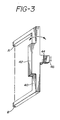
- the mechanism shown in Fig. 3 comprises a C-shaped hinge bar 40, which is mounted on collinear pins A and B, which constrain the bar to rotate about an axis through the pins.
- a bottom surface of the pushbutton rides on surface 42 of the hinge bar as the slider is moved up and down. Regardless of its position along surface 42, the pushbutton when depressed, always provides a force along the axis of switch plunger 44, thereby actuating the swtich 46.
- surface 42 is depicted in Fig. 3 as being an elongated surface, along which a pushbutton on a linear slider (34 in Fig.
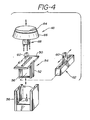
- surface 50 is depicted as being an elongated surface, along which moves knob 48 on shaft 60 of linear slide potentiometer 62; it is clear that surface 50 could be the flat top of a circular disk, along which a knob on the shaft of a rotary potentiometer could move.
- An advantage of the device depicted in Fig. 4 is that it can be very compact.
- Fig. 5 depicts an embodiment of a switch (alone) of the present invention.
- Support plate 70 is adapted for mounting in a conventional wallbox (not shown).
- Switch actuator 72 comprises bezel 74 which is attached to support plate 70 by shaft 76, which passes through slot 78 in faceplate 80.
- pushbutton 82 rides in bezel 74 to actuate a switch (in backbox 84), which is an alternate-action mechanical power switch.
- bezel 74 is depicted in Fig. 5 as having a size of the same order as slot 78, it could alternatively be substanially larger; for example extending over faceplate mounting screws 86 and 88 or over the entire faceplate 80, to provide a smooth appearance, without mounting screws.
- pushbutton 82 could likewise be larger.
- shaft 76 could be in two parts that snap together. One part could be mounted on support plate 70 and the other part attached to bezel 74.
- Fig. 6 depicts a variation on the mechanism shown in Fig. 4, which provides a hidden night light; i.e., a light that is designed to be visible only in a darkened environment.
- the light emanates from lamp 90, which is preferably a neon lamp. Neon is preferred, because these lamps combine long life with the low-current operation needed to meet UL listing requirements.
- Frame 92 has tongues 94, which are constrained by stationary grooves 96. Slider 98 can move back and forth along surface 100 of frame 92. Regardless of the position of slider 98 along surface 100, when pushbutton 102 is depressed, element 104 of frame 92 provides a force along the axis of switch plunger 106 to actuate the switch (not shown).
- Lamp 90 could be located directly below pushbutton 102. Alternatively, as shown in Fig. 6, lamp 90 is horizontally offset. A section of wall 108 is transparent and face 110 makes an angle of 45° with the horizontal (which is greater than the critical angle for total internal reflection for the medium of the section); thus, light from lamp 90 is reflected up through the transparent section of wall 108 and through pushbutton 102. Face 110 may have an opaque, reflective back coating.
- pushbutton 102 is formed of a generally opaque material and has a recess, which leaves a thin section 112 adjacent to the front surface of the pushbutton.
- lamp 90 When lamp 90 is on, light can be seen from a point in front of pushbutton 102.
- the intensity of that light depends on the lamp output, the optical system between lamp and pushbutton, the light-transmitting properties of the pushbutton material, and the geometry of the recess and thin section. These parameters can be adjusted so that the light is visible in a darkened environment. If the pushbutton is of a thermoplastic, molding is a preferred forming process.
- the recess preferably extends over an area that is a relatively small fraction of the top area of the pushbutton, which permits the thin section thickness to be a minimum, less than about 1mm. If the recess extends over too large an area, the thin section cannot easily be molded and, furthermore, would be mechanically weak.
- the optimum recess area for the required section thickness depends on the thermoplastic material and can be determined by routine experimentation.
- Optional light pipe 114 provides higher light intensity, if that is desirable. Still higher light intensity is provided if the lower end 116 of light pipe 114 has a larger lateral dimension than does the upper end 118, adjacent to the thin section.
- Lamp 90 is depicted in Fig. 6 as a stationary source, which is elongated to provide desirably constant light through pushbutton 102, regardless of the position of slider 96. Alternatively, lamp 90 could be joined to slider 98 to move with it to, likewise, provide substantially constant light. If desirable, the power to lamp 90 could be user-adjustable, either mechanically (e.g., filters) or electrically (e.g., a light dimmer).
- the transparent section of wall 108 could be a light pipe and could further provide enhanced light output by having a smaller lateral dimension at the top - near slider 98 - than at the bottom.
- wall 108 is shown in Fig. 6 as an element of frame 92, its element - i.e., transparent section and reflective face - could alternatively be attached to pushbutton 102.
- Fig. 7 depicts a variation on the mechanism of Fig. 3 for providing light through a pushbutton of this invention.
- hinge bar 120 provides a means for transmitting a force between pushbutton 122 and switch 124.
- Hinge bar 120 has a transparent section and a reflective face 126 at 45° to the horizontal to reflect light from lamp 128 through pushbutton 130.
- the transparent section of hinge bar 120 could have a narrow lateral extent and provide a light pipe to enhance the intensity of light to the pushbutton.
- elements 108 of Fig. 6 and 120 of Fig. 7 preferably have transparent sections, it is often more convenient to form them entirely of a transparent material.
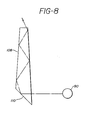
- the light intensity through the pushbutton of the embodiment of Figs. 6 and 7 is enhanced by total internal reflection in the element(s) that direct the light from the lamp to the pushbutton, as is depicted for element 108 (in a wedge-shaped embodiment) in Fig. 8.
Landscapes
- Engineering & Computer Science (AREA)
- Power Engineering (AREA)
- Push-Button Switches (AREA)
- Slide Switches (AREA)
- Arrangement Of Elements, Cooling, Sealing, Or The Like Of Lighting Devices (AREA)
- Switches With Compound Operations (AREA)
- Adjustable Resistors (AREA)
- Switch Cases, Indication, And Locking (AREA)
Applications Claiming Priority (4)
| Application Number | Priority Date | Filing Date | Title |
|---|---|---|---|
| US22597488A | 1988-07-29 | 1988-07-29 | |
| US225974 | 1988-07-29 | ||
| US332254 | 1989-03-31 | ||
| US07/332,254 US4947054A (en) | 1988-07-29 | 1989-03-31 | Sliding dimmer switch |
Publications (3)
| Publication Number | Publication Date |
|---|---|
| EP0352920A2 true EP0352920A2 (de) | 1990-01-31 |
| EP0352920A3 EP0352920A3 (de) | 1991-04-24 |
| EP0352920B1 EP0352920B1 (de) | 1995-11-22 |
Family
ID=26920107
Family Applications (1)
| Application Number | Title | Priority Date | Filing Date |
|---|---|---|---|
| EP19890306816 Expired - Lifetime EP0352920B1 (de) | 1988-07-29 | 1989-07-05 | Schiebbarer Helligkeitssteuerschalter |
Country Status (6)
| Country | Link |
|---|---|
| US (1) | US4947054A (de) |
| EP (1) | EP0352920B1 (de) |
| JP (1) | JPH0275114A (de) |
| AU (1) | AU626306B2 (de) |
| CA (1) | CA1331768C (de) |
| DE (1) | DE68924881T2 (de) |
Cited By (8)
| Publication number | Priority date | Publication date | Assignee | Title |
|---|---|---|---|---|
| EP0608771A1 (de) * | 1993-01-26 | 1994-08-03 | ABBPATENT GmbH | Verfahren und Vorrichtung zum Betätigen von Einbaukomponenten in Kraftfahrzeugen |
| WO2000038205A1 (en) * | 1998-12-23 | 2000-06-29 | Johnson Controls Technology Company | Window control apparatus |
| WO2002021554A1 (en) * | 2000-09-05 | 2002-03-14 | Adc Telecommunications, Inc. | Module for selection of power source |
| EP1032247A3 (de) * | 1999-02-27 | 2003-01-02 | Samsung Electronics Co., Ltd. | Bedienfeld für Mikrowellenofen |
| US6657316B1 (en) | 1998-12-23 | 2003-12-02 | Johnson Contols Interiors Technology Corporation | Window control apparatus |
| WO2006124360A3 (en) * | 2005-05-12 | 2007-04-05 | Lutron Electronics Co | Lighting control having a captured offset linear guide system |
| GB2459495A (en) * | 2008-04-24 | 2009-10-28 | Anthony James Doyle | Switching apparatus |
| EP2337050A1 (de) | 2009-12-18 | 2011-06-22 | Somfy SAS | Steuervorrichtung und Heimanlage, die mit einer solchen Vorrichtung ausgestattet ist |
Families Citing this family (65)
| Publication number | Priority date | Publication date | Assignee | Title |
|---|---|---|---|---|
| USD329635S (en) | 1990-09-11 | 1992-09-22 | Powell Tsai | Double-pole, wall mounted voltage regulator |
| JP2566226Y2 (ja) * | 1992-01-07 | 1998-03-25 | アルプス電気株式会社 | スイッチ装置のつまみ取付構造 |
| US5278736A (en) * | 1992-02-21 | 1994-01-11 | United Technologies Automotive, Inc. | Automobile sun visor vanity mirror module |
| US6005308A (en) * | 1993-03-31 | 1999-12-21 | Lutron Electronics Co., Inc. | Electrical switch and dimmer control device |
| JPH08321409A (ja) * | 1995-05-26 | 1996-12-03 | Matsushita Electric Ind Co Ltd | スライド形可変抵抗器 |
| JP3495182B2 (ja) * | 1996-03-12 | 2004-02-09 | 株式会社東海理化電機製作所 | 多方向スイッチの節度機構 |
| USD384939S (en) * | 1996-04-10 | 1997-10-14 | Pride Health Care, Inc. | Chair control |
| USD415472S (en) | 1998-05-05 | 1999-10-19 | Francis Fredrick Kelso | Toggle/dimmer switch plate |
| USD436934S1 (en) | 1999-06-18 | 2001-01-30 | Pass & Seymour, Inc. | Slide dimmer |
| USD463382S1 (en) | 2000-11-22 | 2002-09-24 | Lutron Electronics Co., Inc. | Dual slide action fan and light control |
| USD457863S1 (en) | 2000-11-22 | 2002-05-28 | Lutron Electronics Co., Inc. | Single slide action light control |
| USD471879S1 (en) | 2001-11-13 | 2003-03-18 | Lutron Electronics Co., Inc. | Dimmer switch |
| USD472527S1 (en) | 2001-11-13 | 2003-04-01 | Lutron Electronics Co. Inc. | Dimmer switch |
| USD477572S1 (en) | 2001-11-13 | 2003-07-22 | Lutron Electronics Co., Inc. | Switch |
| USD477289S1 (en) | 2001-11-13 | 2003-07-15 | Lutron Electronics Co., Inc. | Switch |
| USD477573S1 (en) | 2001-11-13 | 2003-07-22 | Lutron Electronics Co., Inc. | Dimmer switch |
| US6734381B2 (en) * | 2001-11-13 | 2004-05-11 | Lutron Electronics Co., Inc. | Wallbox dimmer switch having side-by-side pushbutton and dimmer actuators |
| USD472526S1 (en) | 2001-11-13 | 2003-04-01 | Lutron Electronics Co., Inc. | Switch |
| USD472221S1 (en) | 2001-11-13 | 2003-03-25 | Lutron Electronics Co., Inc. | Switch |
| USD478554S1 (en) | 2001-11-13 | 2003-08-19 | Lutron Electronics Co., Inc. | Dimmer switch |
| USD471880S1 (en) | 2001-11-13 | 2003-03-18 | Lutron Electronics Co., Inc. | Dimmer switch |
| USD477574S1 (en) | 2001-11-13 | 2003-07-22 | Lutron Electronics Co., Inc. | Dimmer switch |
| US6962505B1 (en) * | 2003-01-09 | 2005-11-08 | Pass & Seymar/Legrand | Electrical switch with placard and remote use indicator |
| US7129850B1 (en) * | 2004-12-14 | 2006-10-31 | Sen-Tien Shih | Automatically actuatable switch device |
| USD541222S1 (en) | 2005-05-03 | 2007-04-24 | Lutron Electronics Co., Inc. | Dimmer switch |
| US7694005B2 (en) | 2005-11-04 | 2010-04-06 | Intermatic Incorporated | Remote device management in a home automation data transfer system |
| US7870232B2 (en) | 2005-11-04 | 2011-01-11 | Intermatic Incorporated | Messaging in a home automation data transfer system |
| US7698448B2 (en) | 2005-11-04 | 2010-04-13 | Intermatic Incorporated | Proxy commands and devices for a home automation data transfer system |
| US7640351B2 (en) | 2005-11-04 | 2009-12-29 | Intermatic Incorporated | Application updating in a home automation data transfer system |
| US20070187714A1 (en) * | 2006-02-15 | 2007-08-16 | Eastman Kodak Company | OLED lighting apparatus and method |
| JP4710648B2 (ja) * | 2006-02-23 | 2011-06-29 | オムロン株式会社 | 安全スイッチ |
| US7745750B2 (en) * | 2006-03-17 | 2010-06-29 | Lutron Electronics Co., Inc. | Dimmer switch having an illuminated button and slider slot |
| US7670039B2 (en) * | 2006-03-17 | 2010-03-02 | Lutron Electronics Co., Inc. | Status indicator lens and light pipe structure for a dimmer switch |
| US7837344B2 (en) * | 2006-03-17 | 2010-11-23 | Lutron Electronics Co., Inc. | Traditional-opening dimmer switch having a multi-functional button |
| USD562260S1 (en) * | 2006-05-23 | 2008-02-19 | Lutron Electronics Co., Inc. | Dimmer switch |
| US7579566B2 (en) * | 2006-05-24 | 2009-08-25 | Lutron Electronics Co., Ltd. | Wallbox dimmer having a sliding cover plate |
| US20090256483A1 (en) * | 2006-06-08 | 2009-10-15 | Lutron Electronics Co., Inc. | Load Control Device Having a Visual Indication of an Energy Savings Mode |
| USD566658S1 (en) | 2006-06-19 | 2008-04-15 | Lutron Electronics Co., Inc. | Dual dimmer switch |
| USD563901S1 (en) * | 2006-06-19 | 2008-03-11 | Lutron Electronics Co., Inc. | Dimmer switch |
| USD572202S1 (en) * | 2006-07-17 | 2008-07-01 | Lutron Electronics Co., Inc. | Dimmer switch |
| USD582863S1 (en) * | 2007-01-31 | 2008-12-16 | Use Lighting Control, Inc. | Dimmer |
| USD574335S1 (en) * | 2007-01-31 | 2008-08-05 | Use Lighting Control, Inc. | Fan speed control |
| USD586761S1 (en) * | 2007-01-31 | 2009-02-17 | Use Lighting Control, Inc. | Fan speed control |
| USD577686S1 (en) * | 2007-01-31 | 2008-09-30 | Use Lighting Control, Inc. | Dimmer |
| USD592031S1 (en) * | 2007-10-18 | 2009-05-12 | Omron Corporation | Portable electric screwdriver |
| USD597496S1 (en) | 2008-08-29 | 2009-08-04 | Lutron Electronics Co., Inc. | Dimmer switch |
| USD597495S1 (en) | 2008-08-29 | 2009-08-04 | Lutron Electronics Co., Inc. | Dimmer switch |
| US8274233B2 (en) | 2008-11-25 | 2012-09-25 | Lutron Electronics Co., Inc. | Load control device having a visual indication of energy savings and usage information |
| US8049427B2 (en) | 2008-11-25 | 2011-11-01 | Lutron Electronics Co., Inc. | Load control device having a visual indication of energy savings and usage information |
| USD616838S1 (en) | 2008-12-19 | 2010-06-01 | Lutron Electronics Co., Inc. | Dimmer switch |
| USD616837S1 (en) | 2008-12-19 | 2010-06-01 | Lutron Electronics Co., Inc. | Dimmer switch |
| USD624881S1 (en) | 2009-03-17 | 2010-10-05 | Lutron Electronics Co., Inc. | Lighting control keypad |
| USD624882S1 (en) | 2009-03-17 | 2010-10-05 | Lutron Electronics Co., Inc. | Lighting control keypad |
| US8340834B1 (en) | 2010-04-16 | 2012-12-25 | Cooper Technologies Company | Occupancy sensor with energy usage indicator |
| USD806681S1 (en) * | 2015-09-09 | 2018-01-02 | Harman International Industries, Incorporated | Audio component switch |
| USD870680S1 (en) * | 2016-01-07 | 2019-12-24 | Lg Electronics Inc. | Detector controller |
| USD831590S1 (en) * | 2016-01-07 | 2018-10-23 | Lg Electronics Inc. | Digital switch |
| USD787453S1 (en) * | 2016-03-09 | 2017-05-23 | Lutron Electronics Co., Inc. | Dimmer switch |
| USD797062S1 (en) | 2016-03-09 | 2017-09-12 | Lutron Electronics Co., Inc. | Dimmer switch |
| USD788050S1 (en) * | 2016-03-09 | 2017-05-30 | Lutron Electronics Co., Inc. | Dimmer switch |
| USD808344S1 (en) * | 2016-03-09 | 2018-01-23 | Lutron Electronics Co., Inc. | Dimmer switch |
| USD787454S1 (en) * | 2016-03-09 | 2017-05-23 | Lutron Electronics Co., Inc. | Dimmer switch |
| USD904319S1 (en) * | 2018-11-16 | 2020-12-08 | Promier Products Inc. | Light switch with sliding actuator and integrated light source |
| USD925477S1 (en) * | 2019-08-30 | 2021-07-20 | Schneider Electric (Australia) Pty Ltd | Control module |
| US11388793B2 (en) * | 2020-07-28 | 2022-07-12 | Ch Lighting Technology Co., Ltd. | Dimmable lighting apparatus |
Family Cites Families (16)
| Publication number | Priority date | Publication date | Assignee | Title |
|---|---|---|---|---|
| JPS571499B1 (de) * | 1971-05-11 | 1982-01-11 | ||
| US3746923A (en) * | 1971-10-18 | 1973-07-17 | Lutron Electronics Co | Dimmer switch with linearly movable control |
| DE7231112U (de) * | 1972-08-23 | 1973-01-11 | Preh Elektrofeinmechanische Werke | Schiebewiderstand mit Schalter |
| JPS51128835A (en) * | 1975-05-01 | 1976-11-10 | Nippon Soken Kk | Catalytic material manufacturing method and manufacturing device there by. |
| US4042903A (en) * | 1976-03-15 | 1977-08-16 | Hunt Electronics Company | Power control slide switch |
| US4104606A (en) * | 1976-12-23 | 1978-08-01 | Lutron Electronics Co., Inc. | Dimmer switch with insulation housing |
| US4306131A (en) * | 1980-06-26 | 1981-12-15 | Gte Products Corporation | Solid state touch control snap switch |
| US4363018A (en) * | 1980-11-03 | 1982-12-07 | Matsushita Electric Industrial Co., Ltd. | Electronic components of rotary type |
| JPS5936208U (ja) * | 1982-08-30 | 1984-03-07 | アルプス電気株式会社 | スライド形可変抵抗器 |
| US4455546A (en) * | 1983-02-28 | 1984-06-19 | Prescolite, A Div. Of U.S. Indus. | Variable resistor and switch assembly having separate sliders |
| DE8322822U1 (de) * | 1983-08-08 | 1983-12-01 | Bosch-Siemens Hausgeräte GmbH, 7000 Stuttgart | Schalterbetätigungselement |
| US4563592A (en) * | 1983-10-13 | 1986-01-07 | Lutron Electronics Co. Inc. | Wall box dimmer switch with plural remote control switches |
| US4672229A (en) * | 1985-12-12 | 1987-06-09 | Southwest Laboratories, Inc. | Wall-mounted touch control switch |
| US4695820A (en) * | 1986-03-13 | 1987-09-22 | Lutron Electronics Co. Inc. | Safety device for apparatus having relatively movable members |
| US4742188A (en) * | 1987-03-24 | 1988-05-03 | Lutron Electronics Co., Inc. | Sliding electrical control |
| US4873403A (en) * | 1987-05-05 | 1989-10-10 | Prescolite, Inc. | On-off switch system for a pair of conductors |
-
1989
- 1989-03-31 US US07/332,254 patent/US4947054A/en not_active Expired - Lifetime
- 1989-07-05 EP EP19890306816 patent/EP0352920B1/de not_active Expired - Lifetime
- 1989-07-05 DE DE68924881T patent/DE68924881T2/de not_active Expired - Fee Related
- 1989-07-13 AU AU38099/89A patent/AU626306B2/en not_active Ceased
- 1989-07-17 CA CA 605810 patent/CA1331768C/en not_active Expired - Fee Related
- 1989-07-25 JP JP1192476A patent/JPH0275114A/ja active Pending
Cited By (10)
| Publication number | Priority date | Publication date | Assignee | Title |
|---|---|---|---|---|
| EP0608771A1 (de) * | 1993-01-26 | 1994-08-03 | ABBPATENT GmbH | Verfahren und Vorrichtung zum Betätigen von Einbaukomponenten in Kraftfahrzeugen |
| WO2000038205A1 (en) * | 1998-12-23 | 2000-06-29 | Johnson Controls Technology Company | Window control apparatus |
| US6657316B1 (en) | 1998-12-23 | 2003-12-02 | Johnson Contols Interiors Technology Corporation | Window control apparatus |
| EP1032247A3 (de) * | 1999-02-27 | 2003-01-02 | Samsung Electronics Co., Ltd. | Bedienfeld für Mikrowellenofen |
| WO2002021554A1 (en) * | 2000-09-05 | 2002-03-14 | Adc Telecommunications, Inc. | Module for selection of power source |
| US6459051B1 (en) | 2000-09-05 | 2002-10-01 | Adc Telecommunications, Inc. | Module for selection of power source |
| WO2006124360A3 (en) * | 2005-05-12 | 2007-04-05 | Lutron Electronics Co | Lighting control having a captured offset linear guide system |
| US7489499B2 (en) | 2005-05-12 | 2009-02-10 | Lutron Electronics Co., Ltd. | Lighting control having a captured offset linear guide system |
| GB2459495A (en) * | 2008-04-24 | 2009-10-28 | Anthony James Doyle | Switching apparatus |
| EP2337050A1 (de) | 2009-12-18 | 2011-06-22 | Somfy SAS | Steuervorrichtung und Heimanlage, die mit einer solchen Vorrichtung ausgestattet ist |
Also Published As
| Publication number | Publication date |
|---|---|
| EP0352920A3 (de) | 1991-04-24 |
| DE68924881D1 (de) | 1996-01-04 |
| DE68924881T2 (de) | 1996-07-04 |
| US4947054A (en) | 1990-08-07 |
| AU3809989A (en) | 1990-02-01 |
| CA1331768C (en) | 1994-08-30 |
| JPH0275114A (ja) | 1990-03-14 |
| EP0352920B1 (de) | 1995-11-22 |
| AU626306B2 (en) | 1992-07-30 |
Similar Documents
| Publication | Publication Date | Title |
|---|---|---|
| EP0352920B1 (de) | Schiebbarer Helligkeitssteuerschalter | |
| US7837344B2 (en) | Traditional-opening dimmer switch having a multi-functional button | |
| CA2645326C (en) | Dimmer switch having an illuminated button and slider slot | |
| US5637930A (en) | Wall-mountable switch & dimmer | |
| US4783581A (en) | Air gap switch assembly | |
| US6005308A (en) | Electrical switch and dimmer control device | |
| US20080001549A1 (en) | Status indicator lens and light pipe structure for a dimmer switch | |
| US5359231A (en) | Wallbox-mountable switch and dimmer | |
| US5030893A (en) | Wall box dimming system and face plate and switch assembly therefor | |
| US20110259720A1 (en) | Electrical device with actuator support and viewing window | |
| US6092903A (en) | Lighted key board | |
| CA1199695A (en) | Variable resistor and switch assembly having separate sliders | |
| JPH06325666A (ja) | 照明付きスイッチ | |
| US4873403A (en) | On-off switch system for a pair of conductors | |
| US4359618A (en) | Push button switch with self-indicating message display | |
| EP0221997A1 (de) | Beleuchteter druckknopfschalter | |
| HK1127734A (en) | Dimmer switch having an illuminated button and slider slot | |
| GB2260026A (en) | Dual function electrical control unit | |
| HK1130362A (en) | Traditional-opening dimmer switch having a multi-functional button | |
| JPH06348938A (ja) | 自動販売機用デイライト装置 |
Legal Events
| Date | Code | Title | Description |
|---|---|---|---|
| PUAI | Public reference made under article 153(3) epc to a published international application that has entered the european phase |
Free format text: ORIGINAL CODE: 0009012 |
|
| AK | Designated contracting states |
Kind code of ref document: A2 Designated state(s): DE FR GB IT |
|
| PUAL | Search report despatched |
Free format text: ORIGINAL CODE: 0009013 |
|
| AK | Designated contracting states |
Kind code of ref document: A3 Designated state(s): DE FR GB IT |
|
| 17P | Request for examination filed |
Effective date: 19910926 |
|
| 17Q | First examination report despatched |
Effective date: 19931202 |
|
| GRAA | (expected) grant |
Free format text: ORIGINAL CODE: 0009210 |
|
| AK | Designated contracting states |
Kind code of ref document: B1 Designated state(s): DE FR GB IT |
|
| PG25 | Lapsed in a contracting state [announced via postgrant information from national office to epo] |
Ref country code: IT Free format text: LAPSE BECAUSE OF FAILURE TO SUBMIT A TRANSLATION OF THE DESCRIPTION OR TO PAY THE FEE WITHIN THE PRE;WARNING: LAPSES OF ITALIAN PATENTS WITH EFFECTIVE DATE BEFORE 2007 MAY HAVE OCCURRED AT ANY TIME BEFORE 2007. THE CORRECT EFFECTIVE DATE MAY BE DIFFERENT FROM THE ONE RECORDED.SCRIBED TIME-LIMIT Effective date: 19951122 |
|
| REF | Corresponds to: |
Ref document number: 68924881 Country of ref document: DE Date of ref document: 19960104 |
|
| ET | Fr: translation filed | ||
| PGFP | Annual fee paid to national office [announced via postgrant information from national office to epo] |
Ref country code: DE Payment date: 19960925 Year of fee payment: 8 |
|
| PLBE | No opposition filed within time limit |
Free format text: ORIGINAL CODE: 0009261 |
|
| STAA | Information on the status of an ep patent application or granted ep patent |
Free format text: STATUS: NO OPPOSITION FILED WITHIN TIME LIMIT |
|
| 26N | No opposition filed | ||
| PGFP | Annual fee paid to national office [announced via postgrant information from national office to epo] |
Ref country code: FR Payment date: 19970530 Year of fee payment: 9 |
|
| PGFP | Annual fee paid to national office [announced via postgrant information from national office to epo] |
Ref country code: GB Payment date: 19970623 Year of fee payment: 9 |
|
| PG25 | Lapsed in a contracting state [announced via postgrant information from national office to epo] |
Ref country code: DE Free format text: LAPSE BECAUSE OF NON-PAYMENT OF DUE FEES Effective date: 19980401 |
|
| PG25 | Lapsed in a contracting state [announced via postgrant information from national office to epo] |
Ref country code: GB Free format text: LAPSE BECAUSE OF NON-PAYMENT OF DUE FEES Effective date: 19980705 |
|
| GBPC | Gb: european patent ceased through non-payment of renewal fee |
Effective date: 19980705 |
|
| PG25 | Lapsed in a contracting state [announced via postgrant information from national office to epo] |
Ref country code: FR Free format text: LAPSE BECAUSE OF NON-PAYMENT OF DUE FEES Effective date: 19990331 |
|
| REG | Reference to a national code |
Ref country code: FR Ref legal event code: ST |