EP0352976B1 - Séparateur de signaux à diversité d'angle utilisant une conversion de mode - Google Patents
Séparateur de signaux à diversité d'angle utilisant une conversion de mode Download PDFInfo
- Publication number
- EP0352976B1 EP0352976B1 EP89307399A EP89307399A EP0352976B1 EP 0352976 B1 EP0352976 B1 EP 0352976B1 EP 89307399 A EP89307399 A EP 89307399A EP 89307399 A EP89307399 A EP 89307399A EP 0352976 B1 EP0352976 B1 EP 0352976B1
- Authority
- EP
- European Patent Office
- Prior art keywords
- diversity
- signal
- waveguide
- version
- separator
- Prior art date
- Legal status (The legal status is an assumption and is not a legal conclusion. Google has not performed a legal analysis and makes no representation as to the accuracy of the status listed.)
- Expired - Lifetime
Links
Images





Classifications
-
- H—ELECTRICITY
- H04—ELECTRIC COMMUNICATION TECHNIQUE
- H04B—TRANSMISSION
- H04B7/00—Radio transmission systems, i.e. using radiation field
- H04B7/02—Diversity systems; Multi-antenna system, i.e. transmission or reception using multiple antennas
- H04B7/10—Polarisation diversity; Directional diversity
-
- H—ELECTRICITY
- H01—ELECTRIC ELEMENTS
- H01P—WAVEGUIDES; RESONATORS, LINES, OR OTHER DEVICES OF THE WAVEGUIDE TYPE
- H01P1/00—Auxiliary devices
- H01P1/16—Auxiliary devices for mode selection, e.g. mode suppression or mode promotion; for mode conversion
Definitions
- This invention is in the field of radiated wave communications; more specifically, it relates to diversity reception apparatus for such communications.
- Multipath fading occurs when the transmitted signal arrives at the receiving antenna via two or more paths in a destructive phase relationship. It has been shown that the destructive phase relationship exists over only a narrow frequency band and a relatively small area of space at any one time.
- a diversity signal may be transmitted and received on a different carrier frequency in the case of frequency diversity, or received by an antenna located a vertical distance away from the primary antenna in the case of space diversity.
- the diversity signal may simply be substituted for the primary signal, or the two signals may be combined using some form of phase or amplitude adjustment.
- angle diversity system can provide significant improvement over space diversity systems in outage time, it appears to be limited in bandwidth, and to suffer approximately 6 db signal loss at the point of crossover between the primary and diversity signals. Further, it is not known how to extend its use to other antenna arrangements.
- An object of this invention is a signal separator that can be used over a broad frequency band with a variety of antenna types to provide improved angle diversity reception.
- Another object is a waveguide signal separator that generates angle diversity signals derived from multimode signals.
- a third object is an angle diversity receiving system operating off a single antenna that provides effective diversity protection of both horizontally and vertically polarized signals over a broad frequency band.
- FIG 1 is an angle diversity system embodying the invention.
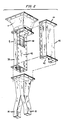
- FIG 2 is a detail drawing of a signal separator according to the invention.
- FIG 3 is a table of electric field distributions useful in explaining the operation of the embodiment of FIG 1.
- FIG 4 is a preferred angle diversity system embodying the invention.
- FIG 5 is a table of electric field distributions useful in explaining the operation of the embodiment of FIG 4.
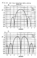
- FIG 6, a and b are plots of far field radiation patterns from square apertures, useful in explaining the operation of the embodiment of FIG 4.
- FIG 7 is a set of plots showing the addition of the patterns of FIG 6.
- FIG 8 is a detail drawing showing the dimensions of one embodiment of a mode separator according to the invention.
- FIG 1 An angle diversity system embodying the invention is shown in FIG 1 in partly pictorial and partly block form.
- a pyramidal horn reflector 2 is aligned to receive the transmitted signals.
- a horn-to-waveguide transition unit 4 often called a "flowerpot” in antenna jargon, connects the received signal to a diversity signal separator 6, which separates primary and diversity signals into respective output ports 8 and 10.
- a dual transition waveguide section 12 provides a smooth transition between the rectangular output ports 8 and 10 and individual square waveguide sections 14 and 16 respectively.
- the horizontally polarized signals are conducted via paths 22 and 24 to a magic Tee 26 or similar 3 db coupling device.
- magic Tee 32 couples out a sum pattern signal, the other output a difference pattern signal to a diversity combining network 28, which selects a signal for receiver 30.
- magic Tee 32 generates sum and difference pattern signals from the vertically polarized primary and diversity signals; these in turn are conducted to a combining network 34 for selection of a signal for receiver 36.
- diversity combiners 28 and 34 are well known in the art.
- the function of the diversity combiners 28 and 34 is to provide a more consistently adequate signal to their respective receivers 30 and 36. To do this they include sensing means to sense one or more parameters of their respective input signals and in one implementation switching means to connect one or the other of the input signals to their respective receivers. This may be considered combining the input signals on a time shared basis. In another implementation they may include continuous combining means using phase and/or amplitude adjusting means so that the signal passed to the receiver is a combination of the primary and diversity signals. Examples of such continuous combining units may be found in U.S. Patent 4,160,952, which issued to K. L. Seastrand July 10, 1979, and in U.S. Patent 4,373,207, which issued to R.P. Hecken February 8, 1983.
- signal separator 6 comprises two rectangular waveguide halves 38 and 40 respectively and a conductive septum 42.
- the inner portion of septum 42 is cut away to be flush with the inner walls of waveguide halves 38 and 40.
- signal separator 6 is an open waveguide of square cross section.
- septum 42 forms a solid conductive wall to divide separator 6 into two separate waveguides of rectangular cross sections.
- a series of posts 48 in the plane of septum 42 form a mode transducing transition between the open square input and the bifurcated output.
- FIGS 1 and 2 support fully reciprocal transmission. With that reciprocity as a justification, therefore, and clarity of understanding as a goal, we will describe the operation of the arrangements of FIG 1 in terms of beam formation by considering, without loss of generality, that the antenna is transmitting instead of receiving.
- the table of FIG 3 shows the electric field patterns that will exist at various locations in the system of FIG 1 under certain excitation conditions.
- Feeding a signal V dv to the difference port of magic Tee 32 forms the set of electric fields shown in the second row of FIG 3.
- This field distribution can be thought of as a combination of two higher order modes TE11 - TM11.
- the far field radiation pattern has a null on boresight with lobes above and below in elevation. This pattern is also called a difference pattern.
- rows 3 and 4 of FIG 3 explain the mode formation and the launching of the corresponding sum and difference patterns.
- the particular form of angle diversity described by FIG 3 could also be called mode diversity.
- FIG 1 can advantageously be used to derive effective diversity signals to maintain system performance from the various directional beams that cause multipath fading.
- the arrangement of FIG 1 requires precise phase alignment at the waveguide junction points.
- the system may be spread over several hundred feet, with square waveguide sections 14 and 16 located near the top of an antenna tower and combiners 28 and 34 normally located in a building at the foot of the tower.
- Polarization couplers 18 and 20 are therefore best connected directly to waveguide sections 14 and 16, and the long runs connecting the sum and difference outputs from magic Tees 26 and 32 and combining units 28 and 34 are best traversed using fundamental mode elliptical waveguide.
- this arrangement has a bandwidth to cover one common carrier frequency band.
- FIG 4 A preferred embodiment with a considerably broader bandwidth and which lacks the critical phase requirements is shown in FIG 4. This arrangement may be similar to that of FIG 1, but simpler in that there is no need for magic Tees; the outputs of polarization couplers 18 and 20 can be connected directly to combiners 28 and 34.
- the operation of the embodiment of FIG 4 can be more readily explained in terms of beam formation by considering the antenna to be transmitting instead of receiving.
- the table of FIG 5 is used in this explanation. Feeding a signal V 1H into the horizontally polarized output of polarization coupler 20 of FIG 4 results in the field distributions given in the first row of FIG 5. Since only one of the two waveguides at plane T-T carries a signal, the field at plane F-F can be thought as being made up of the difference of the two modes TE01 and TE02 shown in the third column.
- FIG 5 The explanation used in connection with FIG 5 made the assumption that the two modes TE01 and TE02, for instance, are added exactly in phase or out-of-phase, TE01 plus TE02 or TE01 minus TE02.
- an exact in-phase or out-of-phase addition is not necessary. Any phase shift is acceptable.
- FIG 6a is a plot of E field strength as a function of elevation angle from boresight for the fundamental mode TE01;
- FIG 6b is a similar plot for the higher order mode TE02.
- FIG 7a shows the vector addition of these two patterns with relative phase difference ⁇ between them of 0 degrees and 180 degrees.
- Curve 41 represents the in phase addition of fundamental and higher order modes i.e., TE01 + TE02 , such as depicted in the second row of the table of FIG 5.
- Curve 42 represents the same addition with a 180 degree phase shift of the TE02 pattern. This is TE01 - TE02 as depicted in the first row of FIG 5.
- Curves 41 and 42 therefore, represent the far field patterns of the signals V 2H and V 1H , respectively. It should be noted that the intersection of curves 41 and 42 occurs 3 db below the maximum signal points.
- Curve 43 represents the vector addition of these two modes; it is the same for TE01 + TE02 and TE01 - TE02, with a peak again only 3 db below the peak of the sum pattern.
- FIG 7 c depicts the phase shift of these resultant signals as a function of elevation angle.
- Curve 44 represents the phase of the sum of the modes and curve 45 the phase of the difference of the modes. Note that although the amplitude patterns are actually identical, there is a strong phase shift with elevation angle that is opposite in sign for the two patterns. This is enough to make angle diversity work.
- phase shift between the modes doesn't have to be controlled.
- Such a control could be very difficult to achieve over a wide band of frequencies in the configuration of FIG 4. This is because the various modes propagate at different speeds in the horn part of the antenna and the modes will therefore have different phase relations (in the aperture plane A-A) as a function of frequency. It should also be noted that in the situation depicted by the pattern of FIG 7a, the phase shift across each beam remains constant.
- the signals may advantageously be guided from waveguide sections 14 and 16 to the inputs of polarization couplers 18 and 20 by various well known structures. These components may be separated by several hundred feet, sections 14 and 16 being near the top of an antenna tower and couplers 18 and 20 at the foot of the tower.
- the square waveguide may be continued over this distance.
- the square waveguide may be flared out into a larger overmoded low loss, circular waveguide commonly used in horn reflector installations.
- polarization couplers 18 and 20 may be connected directly to sections 14 and 16 and band separation networks added if multiband operation is required.
- Another advantage of the invention described is the scaling of the pattern offset angles with frequency. This is due to the use of waveguide modes in beam formation. With offset feeds in the focal plane of a parabolic reflector, the pattern tilt angles are fixed because they are determined by geometric optics. This leads to a crossover loss at boresight that changes with frequency and, in general, cannot be reduced much below 6 db.
- Mode transducing signal separator 6 shown in Fig 2, can be designed using well known approaches.
- This mode transducer is essentially a 3 db directional coupler with two output ports operating into dominant mode waveguide sections 14 and 16 and the other two terminals represented by the sum and difference modes in plane F-F.
- the dimensions of the waveguide sections are chosen, of course, to propagate the desired modes at the operating frequencies.
- the mode transducer In addition to coupling all of the desired modes, as shown in FIG 3 or FIG 5, the mode transducer must provide very good impedance matching looking in both directions to avoid significant reflections.
- this post array structure perturbs only incoming modes whose field is parallel to the posts, eg., TE01.
- TE01 mode the excites only modes with no electric field variation in the direction paralled to the posts, that is, only TE 0m modes.
- this structure can be represented for analysis as a series of inductors separated by the respective waveguide sections. With this analysis, the structure can be designed to eliminate the undesirable TE03 mode. Since it is a propagating mode, excitation of TE03 would represent a loss to the received signal.
- the post array can be formed on a double faced printed wiring board that can be clamped between waveguide halves 38 and 40.
- the septum may also be part of the board.
- FIG 8 shows the dimensions, in inches, of such a configuration that operates well across the 4 and 6 GHz bands and both polarizations.
- the large multimode waveguide section at plane F F is 3.644" square;
- the rectangular sections at plane T T are 1.79" x 3.644", with .064" septum.
- the waveguide sections 14 and 16 are 1.79" square.
- the two dashed line conductive patterns inserted at the antenna end of the mode transducer form capacitive elements to more closely match impedances.
- the signals from a conical horn reflector can be led to the diversity signal separator via circular waveguide and a round to square transition.
- the assemblies connected to the pyramidal horn reflector antenna in FIG 1 and FIG 4 can be used as focal point feeds in parabolic antennas, either center fed or offset fed, or in a Cassegrain configuration, to provide the improved angle diversity performance.
Landscapes
- Engineering & Computer Science (AREA)
- Computer Networks & Wireless Communication (AREA)
- Signal Processing (AREA)
- Variable-Direction Aerials And Aerial Arrays (AREA)
- Aerials With Secondary Devices (AREA)
- Waveguide Switches, Polarizers, And Phase Shifters (AREA)
- Radio Transmission System (AREA)
Claims (13)
- Un séparateur de signaux de diversité à guides d'ondes (6), comprenant une section d'entrée multimode (4) qui supporte à la fois des modes fondamentaux et des modes d'ordre supérieur de signaux d'antenne reçus;
CARACTERISE PAR
une section de sortie divisée en deux branches par une cloison conductrice (42) pour former deux guides d'ondes (38, 40); et
des moyens convertisseurs de modes (48) entre la section d'entrée (4) et la section de sortie, pour convertir des modes d'ordres supérieurs sélectionnés en modes fondamentaux qui se propageront dans la section de sortie à deux branches. - Un séparateur de signaux de diversité à guides d'ondes selon la revendication 1, dans lequel la section d'entrée multimode (4) a une section transversale carrée et les guides d'ondes (38, 40) ont des sections transversales rectangulaires.
- Un séparateur de signaux de diversité à guides d'ondes selon la revendication 2, comprenant en outre des moyens de transition de guides d'ondes (12) couplés aux guides d'ondes rectangulaires respectifs (38, 40) de la section de sortie, pour former deux accès de sortie carrés séparés (14, 16).
- Un séparateur de signaux de diversité à guides d'ondes selon l'une quelconque des revendications précédentes, dans lequel les moyens transducteurs comprennent un réseau de tiges parallèles conductrices de l'électricité (48) dans le plan de la cloison (42) couplant des faces de guides d'ondes adjacentes.
- Un séparateur de signaux de diversité à guides d'ondes selon la revendication 4, dans lequel les tiges (48) sont constituées par des pistes conductrices sur un substrat diélectrique à faibles pertes.
- Un séparateur de signaux de diversité à guides d'ondes selon la revendication 4 ou 5, dans lequel les tiges du réseau qui sont les plus proches de la cloison (42) sont plus épaisses que les tiges qui sont les plus éloignées de la cloison (42).
- Un séparateur de signaux de diversité à guides d'ondes selon l'une quelconque des revendications 4 à 6, dans lequel les tiges du réseau qui sont les plus proches de la cloison (42) sont plus proches les unes des autres que les tiges les plus éloignées de la cloison (42).
- Un séparateur de signaux de diversité à guides d'ondes selon l'une quelconque des revendications 4 à 7, comprenant en outre au moins une tige électriquement isolée des faces de guides d'ondes adjacentes, pour former un élément capacitif.
- Un système de réception en diversité destiné à fournir à des moyens de réception (30) une version de signal améliorée d'un signal émis, comprenant
une structure d'antenne de réception (2) pour recevoir le signal émis;
des moyens de séparation de signaux de diversité selon l'une quelconque des revendications précédentes, le séparateur (6) étant couplé à la structure d'antenne (2) de façon à obtenir une version de signal primaire (VSH) et une version de signal de diversité (VDH) du signal reçu;
des moyens de combinaison (26, 28) pour combiner la version de signal primaire et la version de signal de diversité de façon à produire la version améliorée précitée; et
des moyens appliquant la version de signal améliorée aux moyens de réception (30). - Un système de réception en diversité selon la revendication 9, dans lequel les moyens de combinaison comprennent des moyens de commutation (28) qui sont destinés à combiner la version de signal primaire et la version de signal de diversité en temps partagé pour produire la version de signal améliorée.
- Un système de réception en diversité selon la revendication 9, dans lequel les moyens de combinaison combinent la version de signal primaire et la version de signal de diversité d'une manière continue pour produire la version de signal améliorée.
- Un système de réception en diversité selon la revendication 11, dans lequel les moyens de combinaison comprenant des moyens de couplage (26) pour coupler la version de signal primaire et la version de signal de diversité de façon à produire un signal de somme et un signal de différence, et des moyens de commutation (28) pour combiner la somme et la différence en temps partagé.
- Un système de réception en diversité selon la revendication 11, dans lequel les moyens de combinaison comprennent des moyens de couplage (26) pour coupler la version de signal primaire et la version de signal de diversité de façon à produire leur somme et leur différence, et des moyens de combinaison de signaux de somme et de différence (28) pour combiner la somme et la différence d'une manière continue.
Applications Claiming Priority (2)
| Application Number | Priority Date | Filing Date | Title |
|---|---|---|---|
| US224606 | 1988-07-26 | ||
| US07/224,606 US4914443A (en) | 1988-07-26 | 1988-07-26 | Angle diversity signal separator using mode conversion |
Publications (3)
| Publication Number | Publication Date |
|---|---|
| EP0352976A2 EP0352976A2 (fr) | 1990-01-31 |
| EP0352976A3 EP0352976A3 (fr) | 1991-05-15 |
| EP0352976B1 true EP0352976B1 (fr) | 1994-06-15 |
Family
ID=22841386
Family Applications (1)
| Application Number | Title | Priority Date | Filing Date |
|---|---|---|---|
| EP89307399A Expired - Lifetime EP0352976B1 (fr) | 1988-07-26 | 1989-07-20 | Séparateur de signaux à diversité d'angle utilisant une conversion de mode |
Country Status (6)
| Country | Link |
|---|---|
| US (1) | US4914443A (fr) |
| EP (1) | EP0352976B1 (fr) |
| JP (1) | JP2523186B2 (fr) |
| AU (1) | AU601114B2 (fr) |
| CA (1) | CA1294004C (fr) |
| DE (1) | DE68916122T2 (fr) |
Families Citing this family (11)
| Publication number | Priority date | Publication date | Assignee | Title |
|---|---|---|---|---|
| US4994819A (en) * | 1989-11-24 | 1991-02-19 | Bell Communications Research, Inc. | Pattern diversity in a microwave digital radio system utilizing a single horn reflector antenna |
| DE9017701U1 (de) * | 1990-09-18 | 1992-01-23 | Richard Hirschmann GmbH & Co, 7300 Esslingen | Richtfunkstrecken-Antennenanordnung |
| EP0575788B1 (fr) * | 1992-06-26 | 1997-03-19 | Siemens Aktiengesellschaft | Lanceur multimode XPD-optimisé pour diversité d'angle |
| US5398035A (en) * | 1992-11-30 | 1995-03-14 | The United States Of America As Represented By The Administrator Of The National Aeronautics And Space Administration | Satellite-tracking millimeter-wave reflector antenna system for mobile satellite-tracking |
| US5485168A (en) * | 1994-12-21 | 1996-01-16 | Electrospace Systems, Inc. | Multiband satellite communication antenna system with retractable subreflector |
| WO1997027500A1 (fr) * | 1996-01-26 | 1997-07-31 | The Secretary Of State For Defence | Analyseur de champ de rayonnements |
| ATE325441T1 (de) | 2000-12-27 | 2006-06-15 | Marconi Comm Gmbh | Antenne mit cassegrain-zuführung |
| US7099696B2 (en) * | 2003-02-14 | 2006-08-29 | Radio Frequency Systems, Inc. | Angle diversity dual antenna system |
| US7061445B2 (en) * | 2003-08-26 | 2006-06-13 | Andrew Corporation | Multiband/multichannel wireless feeder approach |
| US9281550B2 (en) | 2013-07-16 | 2016-03-08 | L&J Engineering, Inc. | Wave mode converter |
| JP7687694B2 (ja) * | 2022-11-07 | 2025-06-03 | Necプラットフォームズ株式会社 | デュアルホーンおよびアンテナ装置 |
Family Cites Families (7)
| Publication number | Priority date | Publication date | Assignee | Title |
|---|---|---|---|---|
| US3284725A (en) * | 1962-01-15 | 1966-11-08 | Airtron Division Of Prec Produ | Microwave coupler for combining two orthogonally polarized waves utilizing a ridge-like impedance matching member |
| DE2626925C3 (de) * | 1976-06-16 | 1981-01-08 | Licentia Patent-Verwaltungs-Gmbh, 6000 Frankfurt | Verfahren zum Ausgleich von Ausbreitungsschwankungen bei Nachrichtenübertragungssystemen |
| US4126835A (en) * | 1977-06-20 | 1978-11-21 | Ford Motor Company | Balanced phase septum polarizer |
| US4160952A (en) * | 1978-05-12 | 1979-07-10 | Bell Telephone Laboratories, Incorporated | Space diversity receiver with combined step and continuous phase control |
| US4373207A (en) * | 1980-12-17 | 1983-02-08 | Bell Telephone Laboratories, Incorporated | Space diversity signal combiner |
| DE3111731A1 (de) * | 1981-03-25 | 1982-10-14 | Licentia Patent-Verwaltungs-Gmbh, 6000 Frankfurt | Mikrowellenuebertragungseinrichtung mit mehrmodendiversity-kombinationsempfang |
| US4564935A (en) * | 1984-01-10 | 1986-01-14 | The United States Of America As Represented By The Secretary Of The Air Force | Tropospheric scatter communication system having angle diversity |
-
1988
- 1988-07-26 US US07/224,606 patent/US4914443A/en not_active Expired - Lifetime
-
1989
- 1989-05-30 CA CA000601088A patent/CA1294004C/fr not_active Expired - Lifetime
- 1989-07-19 AU AU38255/89A patent/AU601114B2/en not_active Ceased
- 1989-07-20 EP EP89307399A patent/EP0352976B1/fr not_active Expired - Lifetime
- 1989-07-20 DE DE68916122T patent/DE68916122T2/de not_active Expired - Fee Related
- 1989-07-26 JP JP1191579A patent/JP2523186B2/ja not_active Expired - Lifetime
Also Published As
| Publication number | Publication date |
|---|---|
| US4914443A (en) | 1990-04-03 |
| AU601114B2 (en) | 1990-08-30 |
| EP0352976A2 (fr) | 1990-01-31 |
| EP0352976A3 (fr) | 1991-05-15 |
| JP2523186B2 (ja) | 1996-08-07 |
| DE68916122T2 (de) | 1994-09-22 |
| AU3825589A (en) | 1990-02-01 |
| DE68916122D1 (de) | 1994-07-21 |
| JPH0287704A (ja) | 1990-03-28 |
| CA1294004C (fr) | 1992-01-07 |
Similar Documents
| Publication | Publication Date | Title |
|---|---|---|
| EP0516440B1 (fr) | Antenne à microbande | |
| CA1260609A (fr) | Systeme d'alimentation multiband a large bande passante avec diversite de polarisation | |
| US5268701A (en) | Radio frequency antenna | |
| EP2214251B1 (fr) | Transducteur orthomode de guide d'onde | |
| EP0142555B1 (fr) | Reseau en phase a bande double utilisant un element a large bande avec un diplexeur | |
| US4672384A (en) | Circularly polarized radio frequency antenna | |
| US4473828A (en) | Microwave transmission device with multimode diversity combined reception | |
| US4420756A (en) | Multi-mode tracking antenna feed system | |
| US5909191A (en) | Multiple beam antenna and beamforming network | |
| JP3029231B2 (ja) | 二重円形偏波temモードのスロットアレーアンテナ | |
| US4641144A (en) | Broad beamwidth lens feed | |
| US4583061A (en) | Radio frequency power divider/combiner networks | |
| US8957828B2 (en) | Antenna arrangement for a multi radiator base station antenna | |
| US4912436A (en) | Four port dual polarization frequency diplexer | |
| US4644362A (en) | Waveguide antenna output for a high-frequency planar antenna array of radiating or receiving elements | |
| US6967619B2 (en) | Low noise block | |
| US4914443A (en) | Angle diversity signal separator using mode conversion | |
| US6169518B1 (en) | Dual beam monopulse antenna system | |
| US4365253A (en) | Antenna feeder system for a tracking antenna | |
| EP0189630A1 (fr) | Antenne omnidirectionnelle à haute fréquence et à hyperfréquence | |
| CN117712715B (zh) | 应用于k波段场强生成系统的宽带双极化天线阵列 | |
| US4590479A (en) | Broadcast antenna system with high power aural/visual self-diplexing capability | |
| GB2191044A (en) | Antenna arrangement | |
| US3475756A (en) | Polarization diversity loop antenna | |
| EP0905815A1 (fr) | Antenne à faisceaux multiples et un réseau de formation de faisceaux |
Legal Events
| Date | Code | Title | Description |
|---|---|---|---|
| PUAI | Public reference made under article 153(3) epc to a published international application that has entered the european phase |
Free format text: ORIGINAL CODE: 0009012 |
|
| AK | Designated contracting states |
Kind code of ref document: A2 Designated state(s): DE FR GB IT |
|
| PUAL | Search report despatched |
Free format text: ORIGINAL CODE: 0009013 |
|
| AK | Designated contracting states |
Kind code of ref document: A3 Designated state(s): DE FR GB IT |
|
| 17P | Request for examination filed |
Effective date: 19911030 |
|
| 17Q | First examination report despatched |
Effective date: 19930702 |
|
| GRAA | (expected) grant |
Free format text: ORIGINAL CODE: 0009210 |
|
| AK | Designated contracting states |
Kind code of ref document: B1 Designated state(s): DE FR GB IT |
|
| RAP4 | Party data changed (patent owner data changed or rights of a patent transferred) |
Owner name: AT&T CORP. |
|
| REF | Corresponds to: |
Ref document number: 68916122 Country of ref document: DE Date of ref document: 19940721 |
|
| ITF | It: translation for a ep patent filed | ||
| ET | Fr: translation filed | ||
| PLBE | No opposition filed within time limit |
Free format text: ORIGINAL CODE: 0009261 |
|
| STAA | Information on the status of an ep patent application or granted ep patent |
Free format text: STATUS: NO OPPOSITION FILED WITHIN TIME LIMIT |
|
| 26N | No opposition filed | ||
| PGFP | Annual fee paid to national office [announced via postgrant information from national office to epo] |
Ref country code: DE Payment date: 19970520 Year of fee payment: 9 |
|
| PGFP | Annual fee paid to national office [announced via postgrant information from national office to epo] |
Ref country code: GB Payment date: 19970528 Year of fee payment: 9 |
|
| PGFP | Annual fee paid to national office [announced via postgrant information from national office to epo] |
Ref country code: FR Payment date: 19970609 Year of fee payment: 9 |
|
| PG25 | Lapsed in a contracting state [announced via postgrant information from national office to epo] |
Ref country code: GB Free format text: LAPSE BECAUSE OF NON-PAYMENT OF DUE FEES Effective date: 19980720 |
|
| GBPC | Gb: european patent ceased through non-payment of renewal fee |
Effective date: 19980720 |
|
| PG25 | Lapsed in a contracting state [announced via postgrant information from national office to epo] |
Ref country code: FR Free format text: LAPSE BECAUSE OF NON-PAYMENT OF DUE FEES Effective date: 19990331 |
|
| PG25 | Lapsed in a contracting state [announced via postgrant information from national office to epo] |
Ref country code: DE Free format text: LAPSE BECAUSE OF NON-PAYMENT OF DUE FEES Effective date: 19990501 |
|
| REG | Reference to a national code |
Ref country code: FR Ref legal event code: ST |
|
| PG25 | Lapsed in a contracting state [announced via postgrant information from national office to epo] |
Ref country code: IT Free format text: LAPSE BECAUSE OF NON-PAYMENT OF DUE FEES Effective date: 20050720 |