EP0353023A1 - Dispositif pour enlever le fond des récipients à coke - Google Patents
Dispositif pour enlever le fond des récipients à coke Download PDFInfo
- Publication number
- EP0353023A1 EP0353023A1 EP89307539A EP89307539A EP0353023A1 EP 0353023 A1 EP0353023 A1 EP 0353023A1 EP 89307539 A EP89307539 A EP 89307539A EP 89307539 A EP89307539 A EP 89307539A EP 0353023 A1 EP0353023 A1 EP 0353023A1
- Authority
- EP
- European Patent Office
- Prior art keywords
- coke
- drumhead
- drum
- actuator
- drum body
- Prior art date
- Legal status (The legal status is an assumption and is not a legal conclusion. Google has not performed a legal analysis and makes no representation as to the accuracy of the status listed.)
- Granted
Links
- 239000000571 coke Substances 0.000 title claims abstract description 105
- 241000208967 Polygala cruciata Species 0.000 claims abstract description 54
- 239000002006 petroleum coke Substances 0.000 claims description 13
- 238000004519 manufacturing process Methods 0.000 claims description 11
- 239000003351 stiffener Substances 0.000 claims description 11
- 238000000034 method Methods 0.000 claims description 7
- XLYOFNOQVPJJNP-UHFFFAOYSA-N water Substances O XLYOFNOQVPJJNP-UHFFFAOYSA-N 0.000 description 10
- 238000010791 quenching Methods 0.000 description 5
- 229930195733 hydrocarbon Natural products 0.000 description 4
- 150000002430 hydrocarbons Chemical class 0.000 description 4
- 239000004215 Carbon black (E152) Substances 0.000 description 3
- 229910000831 Steel Inorganic materials 0.000 description 3
- 230000000712 assembly Effects 0.000 description 3
- 238000000429 assembly Methods 0.000 description 3
- 238000004939 coking Methods 0.000 description 3
- 230000002706 hydrostatic effect Effects 0.000 description 3
- 239000010959 steel Substances 0.000 description 3
- 230000003466 anti-cipated effect Effects 0.000 description 2
- 238000009835 boiling Methods 0.000 description 2
- 239000000463 material Substances 0.000 description 2
- 239000003208 petroleum Substances 0.000 description 2
- 230000000171 quenching effect Effects 0.000 description 2
- 238000004227 thermal cracking Methods 0.000 description 2
- 230000009977 dual effect Effects 0.000 description 1
- 239000000428 dust Substances 0.000 description 1
- 239000012530 fluid Substances 0.000 description 1
- 231100001261 hazardous Toxicity 0.000 description 1
- 239000007788 liquid Substances 0.000 description 1
- 230000013011 mating Effects 0.000 description 1
- 238000012986 modification Methods 0.000 description 1
- 230000004048 modification Effects 0.000 description 1
- 239000002245 particle Substances 0.000 description 1
- 239000008188 pellet Substances 0.000 description 1
- 238000009877 rendering Methods 0.000 description 1
- 239000002002 slurry Substances 0.000 description 1
- 150000003384 small molecules Chemical class 0.000 description 1
- 239000007787 solid Substances 0.000 description 1
- -1 steam Substances 0.000 description 1
Images
Classifications
-
- F—MECHANICAL ENGINEERING; LIGHTING; HEATING; WEAPONS; BLASTING
- F16—ENGINEERING ELEMENTS AND UNITS; GENERAL MEASURES FOR PRODUCING AND MAINTAINING EFFECTIVE FUNCTIONING OF MACHINES OR INSTALLATIONS; THERMAL INSULATION IN GENERAL
- F16J—PISTONS; CYLINDERS; SEALINGS
- F16J13/00—Covers or similar closure members for pressure vessels in general
- F16J13/16—Pivoted closures
-
- C—CHEMISTRY; METALLURGY
- C10—PETROLEUM, GAS OR COKE INDUSTRIES; TECHNICAL GASES CONTAINING CARBON MONOXIDE; FUELS; LUBRICANTS; PEAT
- C10B—DESTRUCTIVE DISTILLATION OF CARBONACEOUS MATERIALS FOR PRODUCTION OF GAS, COKE, TAR, OR SIMILAR MATERIALS
- C10B25/00—Doors or closures for coke ovens
- C10B25/02—Doors; Door frames
- C10B25/08—Closing and opening the doors
- C10B25/10—Closing and opening the doors for ovens with vertical chambers
-
- C—CHEMISTRY; METALLURGY
- C10—PETROLEUM, GAS OR COKE INDUSTRIES; TECHNICAL GASES CONTAINING CARBON MONOXIDE; FUELS; LUBRICANTS; PEAT
- C10B—DESTRUCTIVE DISTILLATION OF CARBONACEOUS MATERIALS FOR PRODUCTION OF GAS, COKE, TAR, OR SIMILAR MATERIALS
- C10B33/00—Discharging devices; Coke guides
Definitions
- the field of the present invention is apparatus for dispensing and safely controlling bulk materials such as petroleum coke or other analogous products.
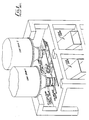
- FIG. 1 illustrates a typical petroleum coke production facility comprising a pair of coke drums mounted in a concrete and/or steel support structure. The drums are positioned above an apron having openings forming the entrance to coke chutes extending below the apron.
- the outlets of the coke drums are closed during the coke production process step by means of steel drumheads that are secured to the drums by a plurality of bolts disposed about the circumference of the coke drum outlets.
- the drumheads are approximately seven feet in diameter and five inches thick.
- the coke drums are alternately unheaded on a time schedule depending on the charge rate of the unit, the coke yield and the number of drums utilized.
- the drumheads are manually removed ("unheaded") by operators who remove the drumhead bolting using pneumatic impact wrenches.
- unheading In order to maintain coke production schedules and a steady coker unit output stream, it is essential that the unheading operation be safely and expeditiously performed. In the production facility of Figure 1, unheading typically takes about ten to thirty minutes.
- the drumhead is supported in place by an adjustable unheading cart that is typically mounted on tracks.
- the drumhead is lowered from the coke drum outlet.
- the head and the cart are then rolled to the side to fully expose the open outlet.
- a collapsible chute is hoisted from the deck to tie the coke drum outlet to the coke chute in the drum support structure to prevent spillage during coke removal.
- the coke is then "cut" from the drum by (a) high pressure water jet(s). This operation of removing coke from the drum takes around two to six hours.
- the drum is subsequently reheaded by reinstalling the head bolts.
- the reheading operation takes around fifteen to forty minutes.
- “shot coke” is produced in lieu of sponge coke.
- “Shot coke” has the consistency of small BB pellets which may or may not be agglomerated into large “coke balls.”
- “Shot coke” and the associated “coke balls” may not form a self supporting mass in the coke drum and may therefore behave as a liquid to impose high hydraulic load on the head similar to water. This fluid-like behavior of the "shot coke” will force the drumhead down with considerable force onto the coke drum unheading cart.
- the coke can also flow out with significant velocity from the gap between the drum and the partially lowered head, a potential hazard to operating personnel, and, if the unheading cart is pinned in place by the partially lowered head, may spread onto the unheading deck and equipment below the deck.
- the coke's fluidity also increases the potential for inadequate drainage of quench water by its tendency to plug the drainage outlets, again leading to excessive loads on the drumhead and the unheading cart.
- "shot coke" production entails the dual problems of safety due to excessive and uncontrolled discharge, and the disruption of production feed cycles due to excessive drumhead and unheading cart loading.
- an alternative method of removing a cokedrumhead providing the ability to withstand the high bottom head loads developed in the case of an inadequate quench water drain, controlling and directing hot water and particulate discharge via the bottom head, enabling the unheading operators to distance themselves from the coke drum outlet during drumhead removal and maximizing coke production throughput, would be desirable.
- the present invention is directed to a coke drum unheading device adapted to achieve the aforementioned objects.
- means are provided for moving the coke drumhead between closed and open positions with respect to the coke drum, which means are operable from a location remote from the coke drum outlet.
- Such means are supported from suitable fixed structure, preferably from the coke drum itself.
- the unheading device of the present invention is shown in a two-drum system configuration.
- a first coke drum 1 and a second coke drum 2 of generally cylindrical shape are positioned in a concrete and/or steel drum support structure 4 over a pair of openings 5 and 6, respectively, which are closed by removable covers 3 when coking operations are in progress.
- the openings 5 and 6 form the entrances to a pair of chutes 7 and 8 extending from the unheading deck 9 that transport the coke from the drums 1 and 2 to a concrete apron for removal and subsequent processing.
- the coke drums 1 and 2 comprise generally frusto conical bottom sections 11 and 12 which terminate at generally cylindrical drum outlets 13 and 14, respectively.
- Circumferentially mounted to the bottom sections 11 and 12 are upper stiffener ring assemblies 15 and 16, respectively, that provide support for the actuator means to be described hereinafter.
- Below the ring assemblies 15 and 16 are additional stiffener ring assemblies 17 and 18 to provide support for a pair of two-ton chain hoists 19 for supporting the collapsible chutes 20.
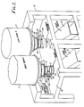
- the upper stiffener ring assembly 15 on the coke drum 1 has attached thereto a pair of main load hydraulic cylinders 21 and 221
- the upper stiffener ring assembly 16 on the coke drum 2 has a pair of main load hydraulic cylinders 23 and 24 mounted thereon.
- Each pair of hydraulic cylinders 21, 22 and 23, 24 form an actuator system capable of resisting anticipated coke and hydrostatic loads during all phases of the unheading operation.
- the present embodiment discloses a hydraulic actuator system having one end connected to the coke drum, a fixed structure, the fixed structure may be provided by an unheading deck suitably reinforced. Other actuator systems would also be possible.
- the actuator systems of the present invention are adapted for operation from locations remote from the coke drum outlets. This enables the unheading operators to avoid the vicinity of the coke drum outlets during unheading operations.
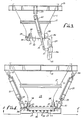
- Each of the coke drums 1 and 2 also includes a drumhead 25 having a generally T-shaped cover stiffener comprising an actuator support portion 26 and a hinge support: portion 27 extending transversely to the actuator support portion 26.
- the hydraulic cylinders 21 and 22 are attached to the upper stiffener ring assembly 15 by pairs of support lugs 28 and 29, respectively, using pins of conventional design to provide a pivotal connection.
- the hydraulic cylinders are attached to the drumhead 25 by means of universal joints 30 and 31 each of which are mounted by pins to the drumhead cover stiffener and one of the hydraulic cylinders to provide a pivotal connection.
- Hydraulic cylinder plunger dust covers 32 and 33 are provided to keep the cylinder plungers free of coke and other foreign matter.
- a circumferential arrangement of bolts 34 is provided extending through mating circumferential flanges on the coke drum outlets 13, 14 and the drumheads 25.
- hinge tabs 35 Mounted to the outlets 13 and 14 of the coke drums 1 and 2 are pairs of hinge tabs 35.
- the drumheads 25, in turn, are provided with hinge tabs 36 extending from the hinge support portions 27 of the cover stiffeners.
- a pin connecting the hinge tabs 35 and 36 provides a pivotal connection between each drumhead 25 and a respective coke drum 1 and 2.
- Other forms of movable connection would also be possible.
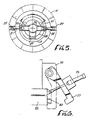
- Each coke drum 1 and 2 is provided with a pair of safety lock devices 37 that secure the drumheads 25 in place while operators are working thereunder to prevent accidental opening in the event of a hydraulic line or cylinder rupture.
- the safety locks 37 shown in detail in Figure 6, are pivotally mounted to the drum outlets 13 and 14 by means of safety lock support tabs 38.
- the safety locks 37 are pivotable between closed and open positions by means of actuators 39. In the closed position the safety locks 37 are aligned with tabs 40 mounted to the drumheads 25 which are sized to support anticipated coke and hydrostatic loads.
- lines 50 and 52 serve to feed hot hydrocarbon to the appropriate drum, and following completion of the coking portion of the cycle serve to remove fluid from that drum.
- the lines 50 and 52 are joined with a flanged connection 54.
- the line 50 is adapted to remain fixed to the drumhead.
- a connection 54 is broken to separate the lines 50 and 52 and permit the drumhead, together with the line 50 to be displaced from the coke drum outlet.
- an actuator controlled unheading device that is operable from a location remote from a drum outlet and which is capable of withstanding high loads. While embodiments and applications of this invention have been shown and described, it will be apparent to those skilled in the art that many more modifications are possible without departing from the inventive concepts herein. For example, as described above, non-hydraulic actuating means such as gear drives and the like could be employed in an actuator system. The invention, therefore, is not to be restricted except in the spirit of the appended claims.
Landscapes
- Chemical & Material Sciences (AREA)
- Engineering & Computer Science (AREA)
- Materials Engineering (AREA)
- Oil, Petroleum & Natural Gas (AREA)
- Organic Chemistry (AREA)
- General Engineering & Computer Science (AREA)
- Mechanical Engineering (AREA)
- Coke Industry (AREA)
Applications Claiming Priority (2)
| Application Number | Priority Date | Filing Date | Title |
|---|---|---|---|
| US22643188A | 1988-07-29 | 1988-07-29 | |
| US226431 | 1988-07-29 |
Publications (2)
| Publication Number | Publication Date |
|---|---|
| EP0353023A1 true EP0353023A1 (fr) | 1990-01-31 |
| EP0353023B1 EP0353023B1 (fr) | 1992-04-22 |
Family
ID=22848883
Family Applications (1)
| Application Number | Title | Priority Date | Filing Date |
|---|---|---|---|
| EP19890307539 Expired EP0353023B1 (fr) | 1988-07-29 | 1989-07-25 | Dispositif pour enlever le fond des récipients à coke |
Country Status (4)
| Country | Link |
|---|---|
| EP (1) | EP0353023B1 (fr) |
| CN (1) | CN1023127C (fr) |
| CA (1) | CA1337863C (fr) |
| DE (1) | DE68901317D1 (fr) |
Cited By (4)
| Publication number | Priority date | Publication date | Assignee | Title |
|---|---|---|---|---|
| EP0690118A1 (fr) * | 1994-06-30 | 1996-01-03 | The M.W. Kellogg Company | Dispositif pour enlever le fond des récipients à coke |
| WO2006039103A2 (fr) | 2004-09-29 | 2006-04-13 | Conocophillips Company | Systeme et procede d'etetage de la sole d'un four a coke |
| US7393435B2 (en) | 2004-03-25 | 2008-07-01 | Petroleo Brasiliero S.A. | Injection charging system in delayed coking drums |
| CN116081136A (zh) * | 2022-12-28 | 2023-05-09 | 大连重矿设备制造有限公司 | 焦罐底闸门密封 |
Citations (2)
| Publication number | Priority date | Publication date | Assignee | Title |
|---|---|---|---|---|
| US1874833A (en) * | 1930-05-29 | 1932-08-30 | Albert L Taylor | Process retort |
| EP0265096A1 (fr) * | 1986-10-09 | 1988-04-27 | Foster Wheeler Energy Limited | Dispositif et procédé pour enlever la tête de tambours de cokéfaction |
-
1989
- 1989-07-25 DE DE8989307539T patent/DE68901317D1/de not_active Expired - Lifetime
- 1989-07-25 EP EP19890307539 patent/EP0353023B1/fr not_active Expired
- 1989-07-28 CA CA 606911 patent/CA1337863C/fr not_active Expired - Fee Related
- 1989-07-29 CN CN 89106363 patent/CN1023127C/zh not_active Expired - Fee Related
Patent Citations (2)
| Publication number | Priority date | Publication date | Assignee | Title |
|---|---|---|---|---|
| US1874833A (en) * | 1930-05-29 | 1932-08-30 | Albert L Taylor | Process retort |
| EP0265096A1 (fr) * | 1986-10-09 | 1988-04-27 | Foster Wheeler Energy Limited | Dispositif et procédé pour enlever la tête de tambours de cokéfaction |
Cited By (6)
| Publication number | Priority date | Publication date | Assignee | Title |
|---|---|---|---|---|
| EP0690118A1 (fr) * | 1994-06-30 | 1996-01-03 | The M.W. Kellogg Company | Dispositif pour enlever le fond des récipients à coke |
| US5500094A (en) * | 1994-06-30 | 1996-03-19 | The M. W. Kellogg Company | Coke drum deheading device |
| US7393435B2 (en) | 2004-03-25 | 2008-07-01 | Petroleo Brasiliero S.A. | Injection charging system in delayed coking drums |
| WO2006039103A2 (fr) | 2004-09-29 | 2006-04-13 | Conocophillips Company | Systeme et procede d'etetage de la sole d'un four a coke |
| EP1796982A4 (fr) * | 2004-09-29 | 2010-03-17 | Conocophillips Co | Systeme et procede d'etetage de la sole d'un four a coke |
| CN116081136A (zh) * | 2022-12-28 | 2023-05-09 | 大连重矿设备制造有限公司 | 焦罐底闸门密封 |
Also Published As
| Publication number | Publication date |
|---|---|
| CA1337863C (fr) | 1996-01-02 |
| CN1040816A (zh) | 1990-03-28 |
| CN1023127C (zh) | 1993-12-15 |
| EP0353023B1 (fr) | 1992-04-22 |
| DE68901317D1 (de) | 1992-05-27 |
Similar Documents
| Publication | Publication Date | Title |
|---|---|---|
| US5098524A (en) | Coke drum unheading device | |
| US7037408B2 (en) | Safe and automatic method for preparation of coke for removal from a coke vessel | |
| EP1451265B1 (fr) | Systeme de dechargement pour tambour a coke | |
| JP4418111B2 (ja) | コークスドラムのための閉じ込め装置 | |
| US5336375A (en) | Delayed coker drumhead handling apparatus | |
| EP1390439B1 (fr) | Systeme modulaire d'etetage et de confinement d'un recipient sous pression | |
| US5048876A (en) | Closure apparatus for pipes and vessels | |
| US20030127314A1 (en) | Safe and automatic method for removal of coke from a coke vessel | |
| EP0804518B1 (fr) | Systeme de goulotte automatisee | |
| US4820384A (en) | Remotely operable vessel cover positioner | |
| WO1996017038A9 (fr) | Systeme de goulotte automatisee | |
| EP0353023B1 (fr) | Dispositif pour enlever le fond des récipients à coke | |
| JPH01190787A (ja) | 直立容器の底部カバーユニットを取外し再び元へ戻すためのカバー開閉装置 | |
| US2595245A (en) | Apparatus for removing drum covers | |
| US5846034A (en) | Automated drill stem guide and method | |
| US7534326B1 (en) | Coke drum bottom unheading system | |
| US7108768B2 (en) | Safety lock boltless closures | |
| EP1796982B1 (fr) | Systeme et procede d'etetage de la sole d'un four a coke | |
| WO2020167367A1 (fr) | Dispositif d'ouverture de fond et entrée pour tambour à coke |
Legal Events
| Date | Code | Title | Description |
|---|---|---|---|
| PUAI | Public reference made under article 153(3) epc to a published international application that has entered the european phase |
Free format text: ORIGINAL CODE: 0009012 |
|
| AK | Designated contracting states |
Kind code of ref document: A1 Designated state(s): DE GB |
|
| RAP1 | Party data changed (applicant data changed or rights of an application transferred) |
Owner name: FLUOR CORPORATION |
|
| 17P | Request for examination filed |
Effective date: 19900205 |
|
| 17Q | First examination report despatched |
Effective date: 19910318 |
|
| GRAA | (expected) grant |
Free format text: ORIGINAL CODE: 0009210 |
|
| AK | Designated contracting states |
Kind code of ref document: B1 Designated state(s): DE GB |
|
| REF | Corresponds to: |
Ref document number: 68901317 Country of ref document: DE Date of ref document: 19920527 |
|
| PLBE | No opposition filed within time limit |
Free format text: ORIGINAL CODE: 0009261 |
|
| STAA | Information on the status of an ep patent application or granted ep patent |
Free format text: STATUS: NO OPPOSITION FILED WITHIN TIME LIMIT |
|
| 26N | No opposition filed | ||
| PGFP | Annual fee paid to national office [announced via postgrant information from national office to epo] |
Ref country code: GB Payment date: 20000614 Year of fee payment: 12 |
|
| PGFP | Annual fee paid to national office [announced via postgrant information from national office to epo] |
Ref country code: DE Payment date: 20000727 Year of fee payment: 12 |
|
| PG25 | Lapsed in a contracting state [announced via postgrant information from national office to epo] |
Ref country code: GB Free format text: LAPSE BECAUSE OF NON-PAYMENT OF DUE FEES Effective date: 20010725 |
|
| GBPC | Gb: european patent ceased through non-payment of renewal fee |
Effective date: 20010725 |
|
| PG25 | Lapsed in a contracting state [announced via postgrant information from national office to epo] |
Ref country code: DE Free format text: LAPSE BECAUSE OF NON-PAYMENT OF DUE FEES Effective date: 20020501 |