EP0353029A2 - Blechlamellen - Google Patents
Blechlamellen Download PDFInfo
- Publication number
- EP0353029A2 EP0353029A2 EP89307559A EP89307559A EP0353029A2 EP 0353029 A2 EP0353029 A2 EP 0353029A2 EP 89307559 A EP89307559 A EP 89307559A EP 89307559 A EP89307559 A EP 89307559A EP 0353029 A2 EP0353029 A2 EP 0353029A2
- Authority
- EP
- European Patent Office
- Prior art keywords
- laminations
- packs
- pack
- formations
- lamination
- Prior art date
- Legal status (The legal status is an assumption and is not a legal conclusion. Google has not performed a legal analysis and makes no representation as to the accuracy of the status listed.)
- Granted
Links
Images




Classifications
-
- H—ELECTRICITY
- H01—ELECTRIC ELEMENTS
- H01F—MAGNETS; INDUCTANCES; TRANSFORMERS; SELECTION OF MATERIALS FOR THEIR MAGNETIC PROPERTIES
- H01F41/00—Apparatus or processes specially adapted for manufacturing or assembling magnets, inductances or transformers; Apparatus or processes specially adapted for manufacturing materials characterised by their magnetic properties
- H01F41/02—Apparatus or processes specially adapted for manufacturing or assembling magnets, inductances or transformers; Apparatus or processes specially adapted for manufacturing materials characterised by their magnetic properties for manufacturing cores, coils, or magnets
- H01F41/0206—Manufacturing of magnetic cores by mechanical means
- H01F41/0233—Manufacturing of magnetic circuits made from sheets
-
- H—ELECTRICITY
- H01—ELECTRIC ELEMENTS
- H01F—MAGNETS; INDUCTANCES; TRANSFORMERS; SELECTION OF MATERIALS FOR THEIR MAGNETIC PROPERTIES
- H01F27/00—Details of transformers or inductances, in general
- H01F27/24—Magnetic cores
- H01F27/245—Magnetic cores made from sheets, e.g. grain-oriented
-
- Y—GENERAL TAGGING OF NEW TECHNOLOGICAL DEVELOPMENTS; GENERAL TAGGING OF CROSS-SECTIONAL TECHNOLOGIES SPANNING OVER SEVERAL SECTIONS OF THE IPC; TECHNICAL SUBJECTS COVERED BY FORMER USPC CROSS-REFERENCE ART COLLECTIONS [XRACs] AND DIGESTS
- Y10—TECHNICAL SUBJECTS COVERED BY FORMER USPC
- Y10T—TECHNICAL SUBJECTS COVERED BY FORMER US CLASSIFICATION
- Y10T29/00—Metal working
- Y10T29/49—Method of mechanical manufacture
- Y10T29/49002—Electrical device making
- Y10T29/4902—Electromagnet, transformer or inductor
- Y10T29/49075—Electromagnet, transformer or inductor including permanent magnet or core
- Y10T29/49078—Laminated
Definitions
- This invention relates to improved laminations for electromagnetic devices for making up magnetic cores thereof, to packs of said laminations and to methods of assembling said packs to form magnetic cores.
- Electromagnetic devices e.g. transformers and electric motors commonly have cores made up of individual laminations which may take the form of a butted stack, an interleaved stack or a so-called "Unilam" stack (see Patent No's GB-A-1466878, 1466879 and 1466880).
- a variety of ways have been used to hold the laminations together to make a core for the device. They have been bolted together. They have been welded together. They have been adhered together. They have been enclosed within a retaining frame. But all these methods are costly because they involve additional components and/or add to the time and number of operations needed to assemble the core.
- one of the laminations has small narrow projections that are a force or interference fit into corresponding recesses of a complementary lamination. But is is inherent in the force fit method of assembly that the complementary parts resist assembly, and any resulting incompleteness in the mechanical contact between the assembled parts increases the magnetic reluctance of the device, and corresponding loss of efficiency. Furthermore the said US Patent does not rely on force fitting as sole means for holding the laminations together but also fastens the laminations by welding as is conventional in the art. Force fitting is also described in Specification No's DE-A-2744711, 3008598 and 3008599. Our Patent Specification No.
- EP-A-0028494 describes and claims F-lamination parts for use in the magnetic cores of transformers having projections and recesses that are subject to an interference fit or act as spring clips. In the latter form, restoring force in the side limbs of the laminations holds the overlapping centre limbs forming the core tightly against one another, providing a frictional resistance to disassembly of the part.
- the invention provides a lamination assembly for an electromagnetic device comprising first and second packs of complementary laminations that fit together and have portions that are resiliently or permanently deformable to clamp the first and second packs of laminations together, subject to the proviso that when the portions are resiliently deformable their limbs abut but do not overlap.
- first and second packs fit relatively freely together and the portions clamp the packs together by permanent deformation.
- the facility to assemble the laminations freely together enables them to be offered together and held in good mechanical contact by an external clamping force until the deformable portions are mechanically deformed to hold the packs together.
- the invention also provides a lamination assembly for an electromagnetic device comprising first and second packs of complementary laminations that fit together and have portions that are resiliently or permanently deformable to clamp the first and second packs of laminations together, the laminations of the first and second packs occurring in pairs whose outlines are such that they nest within one another and can be cut from sheet substantially without waste.
- the invention provides a method of assembling laminations of an electromagnetic device, which comprises: providing first and second packs of complementary laminations that fit relatively freely together and have interfitting formations; holding the first and second packs of laminations positively together in mechanical contact; and deforming said formations on one or both of the laminations to engage the interfitting formations of the other lamination to clamp the first and second packs of laminations together.
- the interfitting formations of the first and second packs of laminations may simply give rise to a frictional clamping force when deformable ones of them are deformed onto non-deforming others of them but preferably they are profiled so that deformation of said formations mechanically fastens the first and second packs together.
- the interfitting formations of the first and second packs of laminations advantageously have a dovetail or other profile such that deformation of said formations positively urges the first and second packs of laminations together.
- the dovetail is advantageously formed on the non-deforming seat formation but it may also be formed on a deformable ear formation.
- the free interfitting is provided by a clearance fit but it may also be provided by a transition fit, line contact between the male and female parts offering little resistance to assembly. Any force needed to assemble the stacks of laminations together should be relatively small compared to the available clamping force.
- the properties of the product may be acceptable if the resistance reduces during the last part of the travel of the first and second packs of laminations towards the fully abutted position.
- the invention provides a lamination assembly for an electromagnetic device formed by fastening together first and second packs of complementary laminations, wherein:
- the invention further provides a pack of laminations for use in an electromagnetic device, said laminations having spaced convergent faces for receiving projections of laminations of a complementary pack that when deformed onto said faces lock the packs of laminations together.
- the invention yet further provides a pack of laminations for use in an electrosagnetic device, said laminations having spaced clamping projections for fitting onto convergent faces of laminations of a complementary pack and that when deformed onto said faces mechanically lock the laminations together.
- the above method of assembly can be used for loose laminations and torsionally flexible stacked laminations.
- a rigid pack of E-laminations may be assembled to a pack of I- laminations which is flexible e.g. because the undivided laminations are held together by a single peg.
- the I-laminations easily accomodate any irregularities in the E-laminations and good mechanical and magnetic contact is obtained.
- the use of two or more pegs for both E-laminations and I-laminations is within the invention.
- the invention provides a lamination for use in an electromagnetic device having spaced convergent faces for receiving projections of a complementary lamination that when deformed onto said faces lock the laminations together.
- the invention provides a lamination for use in an electromagnetic device having spaced clamping projections for fitting onto convergent faces of a complementary lamination and that when deformed onto said faces mechanically lock the laminations together.
- the invention yet further provides a lamination assembly for an electromagnetic device comprising first and second packs of complementary laminations that fit together and have portions that are resiliently or permanently deformable to clamp the first and second packs of laminations together, one of the packs of laminations having abutment formations that give rise to a reaction to the force on limbs of the other pack of laminations during clamping and at least partly prevent permanent deformation of said limbs of said other pack.
- first and second packs are spring clipped together.
- side limbs of one of the packs may be deformed inwardly during clipping together, but preferably deform outwardly so that a transformer core on a centre limb of said one pack is not compresssed as the first and second packs are clipped together.
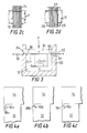
- a transformer 10 has windings 11 and a core assembled from an E-lamination pack 12 and an I-lamination pack 14.
- the laminations of the E-lamination pack 10 are held together by a pair of stamped-in spigot and socket fasteners.
- the upper extremities of the E-laminations of the pack 12 are formed on the outer edges thereof with dovetail formations 16 and the I-laminations of the pack 14 are formed with deformable projections or ears 18.
- the dovetail formations 16 and the ears 18 are desirably formed on the respective laminations during stamping or pressing thereof.
- the size or length and width of the lugs and the size and profile of the dovetail groove vary depending on the size, weight and stack length of the intended transformer assembly.
- the E-lamination pack 12 is placed in a jig, the windings 11 is placed on the centre limb of the E-laminations and the I-lamination pack is placed onto the E-lamination pack and is a loose fit thereon.
- Clamping force F is applied to urge the packs 12,14 into good mechanical contact, which is assisted if the I-pack 18 is torsionally flexible. Good mechanical contact avoids interruption of the magnetic flux path in the assembled core and hence loss of efficiency.
- An inwards deformation D ( Figure 2b) is then caused by impact e.g. of appropriately profiled crimping fingers onto the ears 18 to seat them onto the dovetail formations and to fasten the E- and I-lamination packs 12, 14 together mechanically. Because of the dovetail formations, the act of deformation also pulls the I-stack 14 firmly against the E-stack 12. The resulting attachment between the lamination packs 12, 14 is sufficiently strong and permanent that no additional method of attachment is needed, through adhesive or other conventional means of holding the packs together may be employed if desired.
- the assembled transformer has the appearance shown in Figures 2a and 2c.
- pre-stacked crimped transformer laminations has a number of advantages during assembly.
- No welding, laminating or selector "butt stack" machine is required and assembly can be carried out inexpensively and in high volume.
- Production control is easy, and the stacks can be disassembled and re-crimped if required whereas a welded lamination assembly cannot be taken apart and reassembled if a fault occurs.
- Loose laminations can lean during conventional welding and clamping operations, giving a reduced butt register which can affect the electrical performance of the lamination assembly.
- Pre-stacked E- and I-lamination stacks in which adjacent laminations are connected together by pegs or the like are square to each other giving a good butt register, especially where the I-stack has a single locking peg and is torsionally flexible as disclosed in our Patent Specification No. GB-A-2206453.
- the E-laminations 25 are loose rather than adhered to one another in a pack and are held together by locator formations 26 of the bobbin 11.
- the laminations 25 are attached to a pack of I-laminations 27 as described above.
- the E-laminations can also be stacked laminations held together by one or more impingement pegs.
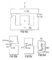
- Figure 3 shows diagrammatically the transformer winding 11 and laminations 12, 14 in a jig 30 during assembly thereof, crimping blades 32 having angled end faces 34 impinging on the projections or ears 18 to bring about the required inward deformation thereof.
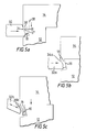
- FIGS 4a-4c Various notch and ear profiles are shown in Figures 4a-4c.
- the notch 16 is a plain dovetail and the ear 18a extends part way e.g. slightly over half way along it.
- the dovetail surface of the notch 16b is doubly curved.
- the notch 16c is again angular, but its lower face is inclined away from rather than parallel to the end face of the E-lamination 12 and the ear 18c extends substantially the whole way along the dovetail notch.
- the blade 32 has a plain inclined surface 34.
- the impact of blade 32 on the ear 18 both deforms the ear inwardly and causes a slight extensiion thereof as indicated by arrow 36.
- the angle between the working face of the dovetail notch 16 and a normal 38 to the end surface of the E-laminations 12 is advantageously above about 5 o and may have whatever value is needed to bring about secure attachment of the lamination packs 12, 14. Angles above and below 5 o may be used, the angle being selected in any individual case depending on the size and weight of the intended core structure.
- the arrangement of Figure 5b is similar except that the end face 34a of the blade 32a is ribbed as shown.
- the blade 32b has an angled line of action to increase the component along the notch 16 and has a convexly curved end face 36b to maximise crimp and extrusion pressure on the ear 18.
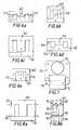
- FIG. 6 there are shown various possible core configurations.
- a choke core having a pair of E-laminations 40 with an air-gap 42 between the central limbs 44.
- Figure 6b shows another choke core formed by a U-lamination 46 and a T-lamination 48.
- a third choke core is formed by E-lamination 50 and I-lamination 52.
- Figure 6d shows a transformer core formed by a pair of F-laminations 54.
- one of the laminations 54 has the notches or recesses 56 and the other has the clamping ears 58.
- Figure 6e shows a further transformer core formed by a U-lamination 60 and a T-lamination 62. In this structure, inclined surfaces 64 on the T-lamination 62 receive clamping ears 66 on the U-lamination 60.
- FIG. 7 a structure is shown for a shaded pole electric motor having a rotor 70 that rotates in a stator defined by U-laminations 72.
- a pole bobbin 74 on lamination pack 76 is attached to by clamping ears and recesses as previously described.
- FIGs 8a-8c there is shown an arrangement for an interleaved stack of E and I laminations 80,81.
- the I-laminations 81 nest within the E-laminations 80 and can be cut from sheet by a progressive forming tool substantially without waste.
- the sides of the E-laminations 80 are formed with recesses 82 typically of semi-circular shape which, as seen in Figure 8b, alternate with the ears and recesses 16,18 in the assembled interleaved stack.
- the ends 18a of the ears 18 are convexly curved to produce correspondingly curved recesses in the E-member 18. The curvature is selected to minimise disturbance to the flux path in the assembled transformer core.
- the I-laminations 81 and the E-laminations 80 have spigot and socket connectors 83, 85 whose number and location is selected depending upon the size and other characteristics of the core being made.
- an I-lamination 90 fits to an E-lamination 92 to form a transformer core.
- the I-lamination 90 has depending projections or ears 94 offset sligthly inwards from its ends 96 that fit into notches 98 in the end faces of the E-laminations 92. Assembly is by crimping inwards the thin material of the outer faces of the notches 98 as shown by arrows 100 using crimping blades, of the kind previously described.
- a "Unilam" type core is formed in which an E-lamination 102 having an extended side limb 104 receives an abbreviated I-lamination 106.
- the E-lamination 102 has a slot 103 in the inner side face of its extended side limb 104 and a slot 108 in the end face of its other side limb that receive corresponding projections or ears on the I-laminations 106. It will be noted that the slots 103, 108 and the corresponding lines of action of the necessary crimping blades are directed generally at right angles to one another as shown by arrows 110, 112.
- Figures 11, 11a and 12,12a Details of the possible slot and ear formations of the I- and E-laminations are shown in Figures 11, 11a and 12,12a which are respectively before and after deformation.
- Figure 11a the dovetail surface 111 is formed on the deformable outer portion of the slot 98 and in Figure 12a it is formed at 114 on the outer surface of ear 94.
- the fastening system described above has a number of advantages. It enables a core from an electromagnetic device to be assembled rapidly and inexpensively.
- the laminations can be made nearly without waste.
- the method can be used for assembly of loose lamination transformers and stacked lamination transformers or transformers having laminations which are partly stacked and partly loose or inter-leaved lamination transformers. Tests have shown that the efficiency of an assembled core according to the invention is substantially the same as or only slightly less than that of a conventionally assembled core.
- Figures 13 and 13a show a yet further profile for a slot and ear which can be used when high retaining force is required.
- One pack of laminations has an ear 120 having a convex blind face 122 which is deformable into contact with a concavity 124 in the other pack of laminations 126.
- the convex blind face 122 initially passes face 125 of lamination 126 with clearance but after deformation mechanically interlocks therewith.
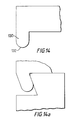
- Figures 14 and 14a show a notch profile in which one pack of laminations has ears 130 having rounded ends 132. These ear profiles are effective from the standpoint of clamping the lamination packs together but enable easier tool manufacture and reduce tool wear during production.
- an E-stack of laminations 134 and I-stack of laminations 136 have complementary dovetail formations 138 and ears 140.
- Rounded ends 142 or ends of other cam profile are formed on the ears 140.
- the ears 140 are angled similarly to or slightly less than the angle of the dovetail formation.
- the distance across the tips of dovetail formations 138 is typically 0.5 mm greater than the gap between the inner faces of ears 138 although this dimension may vary depending upon lamination size and material. If pressure F is applied between stacks 136, 138 the two stacks can be clipped together.
- the I-stacks 136 does not flex, but the legs of the E-stack 134 flex sufficiently (without permanent deformation) to allow the two stacks to be locked together.
- the force F is similar in magnitude to the force required to bring about ear crimping in the earlier embodiments and the I- and E- laminations are butted together suffiently tightly to provide adequate electrical performance.
- the dovetail formations 138 are formed with corners 142 of larger radius than the internal corners 144 of the ears 140 or are formed with bevelled corners so that the stacks 134, 136 come into abutment without interference. With this arrangement, effective abutment of stacks 134, 136 in production is not jeopardised by tool wear.
- the ears 140a have enlarged bulbous ends when viewed in profile and the dovetail formations 138a are relieved to define lead-in surfaces 139 that cam the side legs of the stack 134 inwardly as the stacks 134, 138 are pushed together.
- a problem can arise from deflection of the outer limbs during crimping of stacks of lamination having relatively long limbs or made from material less than 0.5 mm thick e.g. of thickness 0.2 to 0.5 mm. If the outer limbs 16 deflect during crimping as indicated in Figure 16 by the arrow 150 an air gap 151 can form between the centre limb 152 of the E- stack 12 and the I- limb 14. Development of an air gap 151 can result in a deterioration in the electrical performance of a transformer other than a choke-ballast transformer where an air gap is required.
- means for preventing inward deformation of the outer limbs of the E- stack ( Figures 17 and 18).
- Such means may comprise a small raised nipple 154 on some or all of the laminations of the I- stack 14, the laminations 154 being located towards but spaced from the ends of the I- stack 14.
- the outer limbs of the E lamination stack 12 fit between their respective nipple 154 and a respective ear 18.
- the small nipple 154 prevents the outer limbs of the E- stack from deflecting under the crimping pressure and in turn prevents development of undesired air gaps.
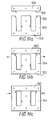
- FIGS 19a-19c show a further form of the invention in which an I-lamination stack 150 and an E-lamination stack 162 clip together by resilient outward deformation of side limbs 164 of the E-lamination.
- the side limbs 164 are formed at the ends on the inner edges with mortise formations 166 as shown in Figure 16d and the I-lamination stack is formed with tenon formations 168 spaced outwardly from its ends as shown.
- the I-stack ears 168 make contact with the E-stack legs 164 ( Figure 19b) the legs 164 flex outwards as indicated by arrows to allow the I-stack ears 168 to pass and to nestle into the E-stack dovetail or mortise 166.
Landscapes
- Engineering & Computer Science (AREA)
- Power Engineering (AREA)
- Manufacturing & Machinery (AREA)
- Manufacturing Cores, Coils, And Magnets (AREA)
- Laminated Bodies (AREA)
- Thermotherapy And Cooling Therapy Devices (AREA)
- Cooling Or The Like Of Semiconductors Or Solid State Devices (AREA)
- Table Devices Or Equipment (AREA)
- Coils Of Transformers For General Uses (AREA)
- Electromagnets (AREA)
Applications Claiming Priority (4)
| Application Number | Priority Date | Filing Date | Title |
|---|---|---|---|
| GB8817875A GB2221354B (en) | 1988-07-27 | 1988-07-27 | Improvements in laminations |
| GB8817875 | 1988-07-27 | ||
| GB888830408A GB8830408D0 (en) | 1988-07-27 | 1988-12-30 | Improvements in laminations |
| GB8830408 | 1988-12-30 |
Publications (3)
| Publication Number | Publication Date |
|---|---|
| EP0353029A2 true EP0353029A2 (de) | 1990-01-31 |
| EP0353029A3 EP0353029A3 (en) | 1990-05-23 |
| EP0353029B1 EP0353029B1 (de) | 1995-10-18 |
Family
ID=26294204
Family Applications (1)
| Application Number | Title | Priority Date | Filing Date |
|---|---|---|---|
| EP89307559A Expired - Lifetime EP0353029B1 (de) | 1988-07-27 | 1989-07-25 | Blechlamellen |
Country Status (8)
| Country | Link |
|---|---|
| US (1) | US5047745A (de) |
| EP (1) | EP0353029B1 (de) |
| JP (1) | JPH02154401A (de) |
| AT (1) | ATE129357T1 (de) |
| DE (1) | DE68924566T2 (de) |
| ES (1) | ES2079380T3 (de) |
| GB (1) | GB2222030B (de) |
| GR (1) | GR3018704T3 (de) |
Cited By (5)
| Publication number | Priority date | Publication date | Assignee | Title |
|---|---|---|---|---|
| EP0571242A1 (de) * | 1992-05-21 | 1993-11-24 | Acec Ballasts | Magnetkreis mit Luftspalt, insbesondere für Vorschaltgeräte für Entladungslampen und Verfahren zu seiner Herstellung |
| EP0374524B1 (de) * | 1988-12-20 | 1994-03-30 | Magnetek May & Christe GmbH | Kernblechpaar und Kernpaket für Manteltransformatoren |
| WO1998047158A1 (en) * | 1997-04-11 | 1998-10-22 | Siemens Energy & Automation, Inc. | Magnetic assembly for a transformer or the like |
| CN101546643B (zh) * | 2008-03-26 | 2012-05-09 | 上海吴淞电气实业有限公司 | 一种电磁式电压互感器铁心及其搭建方法 |
| CN103700467A (zh) * | 2013-11-08 | 2014-04-02 | 浙江肯得机电股份有限公司 | 焊机变压器铁芯硅钢片的结构及连续冲压和自动叠装方法 |
Families Citing this family (19)
| Publication number | Priority date | Publication date | Assignee | Title |
|---|---|---|---|---|
| JP2888142B2 (ja) | 1993-11-08 | 1999-05-10 | 三菱電機株式会社 | 回転電動機並びにその製造方法 |
| GB2254964A (en) * | 1991-03-26 | 1992-10-21 | Scott & Co Ltd Geo | Transformer core assembly |
| AU683849B2 (en) * | 1992-08-21 | 1997-11-27 | Fisher & Paykel Appliances Limited | Electric fan motor |
| US6121711A (en) * | 1993-11-08 | 2000-09-19 | Mitsubishi Denki Kabushiki Kaisha | Rotary motor and production method thereof, and laminated core and production method thereof |
| GB2310545B (en) * | 1996-02-22 | 2000-04-19 | Honda Motor Co Ltd | Stator core and method and apparatus for assembling same |
| US6218927B1 (en) | 1999-02-17 | 2001-04-17 | Abb Power T&D Company Inc. | Stacked magnetic transformer core with center leg curvilinear S-joints |
| US6523247B2 (en) | 2001-01-03 | 2003-02-25 | Copeland Corporation | Motor stator with loose laminations |
| US6583701B2 (en) * | 2001-06-14 | 2003-06-24 | Lite-On Electronics, Inc. | Inductor with variable air-gap separation |
| IL154199A0 (en) * | 2003-01-30 | 2003-07-31 | Eltam Ein Hashofet | Cores and core laminations for elctromagnetic devices |
| TWI269512B (en) * | 2004-10-20 | 2006-12-21 | Yi-Yin Lin | Punched sheet for stator of shaped pole type motor |
| US7646281B2 (en) * | 2005-01-14 | 2010-01-12 | Lincoln Global, Inc. | Snap-together choke and transformer assembly for an electric arc welder |
| WO2007133399A2 (en) * | 2006-05-09 | 2007-11-22 | Spang & Company | Electromagnetic assemblies, core segments that form the same, and their methods of manufacture |
| ITRN20080054A1 (it) * | 2008-11-28 | 2009-02-27 | Icem Spa | Dispositivo trasformatore elettrico , in particolare per lampade a scarica. |
| KR101018260B1 (ko) * | 2009-06-30 | 2011-03-03 | 삼성전기주식회사 | 변압기 |
| US8276279B2 (en) | 2010-08-09 | 2012-10-02 | Wahl Clipper Corporation | Hair clipper with a vibrator motor |
| KR101197234B1 (ko) * | 2011-04-08 | 2012-11-02 | 주식회사 아모그린텍 | 비정질 금속 코어와, 이를 이용한 유도장치 및 그 제조방법 |
| CN104444401B (zh) * | 2014-11-04 | 2016-06-29 | 邱建雄 | 面向变压器铁芯制造的硅钢片自动化叠装系统 |
| EP3232450A1 (de) * | 2016-04-13 | 2017-10-18 | Vihriälä, Harri | Magnetflüssigkeit und besondere geometrie für teile einer elektromagnetischen vorrichtung |
| CN114762241B (zh) | 2019-12-05 | 2026-04-21 | 尚科宁家运营有限公司 | 电动机部件亚微米径向对准和气流管理以延长电机寿命的技术 |
Family Cites Families (15)
| Publication number | Priority date | Publication date | Assignee | Title |
|---|---|---|---|---|
| GB602290A (en) * | 1940-06-26 | 1948-05-24 | Philips Nv | Improvements in or relating to magnetic circuits |
| GB550191A (en) * | 1941-01-28 | 1942-12-28 | British Thomson Houston Co Ltd | Improvements in and relating to magnetic cores and methods of making the same |
| DE1613628A1 (de) * | 1967-03-20 | 1970-07-30 | Blum Eisen & Metallind | Zweiteiliger Eisenkern,insbesondere fuer Transformatoren |
| FR1550392A (de) * | 1967-11-08 | 1968-12-20 | ||
| NL6900779A (de) * | 1968-03-04 | 1969-09-08 | ||
| US3587020A (en) * | 1969-07-01 | 1971-06-22 | Waasner B | Two-part core sheet for transformers |
| GB1345523A (en) * | 1970-09-10 | 1974-01-30 | Friedland Ltd V E Doggart J Sk | Transformer laminations |
| DE2139010A1 (de) * | 1971-08-04 | 1973-03-08 | Kammeyer Karl | Geteilter kernblechschnitt fuer transformatoren |
| DE2711855A1 (de) * | 1977-03-18 | 1978-09-21 | Erich Grau | Mantelblech fuer trafos |
| DE2744711C2 (de) * | 1977-10-05 | 1983-01-05 | Bruno 8550 Forchheim Waasner | Zweiteiliges Manteltransformator-Kernblech mit Verriegelung |
| NL7803966A (nl) * | 1978-04-14 | 1979-10-16 | Philips Nv | Smoorspoel. |
| EP0028494B1 (de) * | 1979-11-02 | 1984-06-20 | Linton And Hirst Limited | Verfahren zum Herstellen von Blechlamellen für Transformatorkerne |
| DE3008599A1 (de) * | 1980-03-06 | 1981-09-17 | Bruno 8550 Forchheim Waasner | Blechkern fuer eine drossel |
| DE3318370C2 (de) * | 1983-05-20 | 1986-02-06 | Waasner, Bruno, 8550 Forchheim | Blechkern aus zwei Teilen und mit drei Schenkeln |
| JPS62285407A (ja) * | 1986-06-03 | 1987-12-11 | Sadao Ito | トランス |
-
1989
- 1989-07-25 EP EP89307559A patent/EP0353029B1/de not_active Expired - Lifetime
- 1989-07-25 GB GB8917025A patent/GB2222030B/en not_active Expired - Fee Related
- 1989-07-25 AT AT89307559T patent/ATE129357T1/de not_active IP Right Cessation
- 1989-07-25 ES ES89307559T patent/ES2079380T3/es not_active Expired - Lifetime
- 1989-07-25 DE DE68924566T patent/DE68924566T2/de not_active Expired - Fee Related
- 1989-07-26 US US07/385,853 patent/US5047745A/en not_active Expired - Fee Related
- 1989-07-27 JP JP1196468A patent/JPH02154401A/ja active Pending
-
1996
- 1996-01-17 GR GR960400105T patent/GR3018704T3/el unknown
Cited By (7)
| Publication number | Priority date | Publication date | Assignee | Title |
|---|---|---|---|---|
| EP0374524B1 (de) * | 1988-12-20 | 1994-03-30 | Magnetek May & Christe GmbH | Kernblechpaar und Kernpaket für Manteltransformatoren |
| EP0571242A1 (de) * | 1992-05-21 | 1993-11-24 | Acec Ballasts | Magnetkreis mit Luftspalt, insbesondere für Vorschaltgeräte für Entladungslampen und Verfahren zu seiner Herstellung |
| WO1998047158A1 (en) * | 1997-04-11 | 1998-10-22 | Siemens Energy & Automation, Inc. | Magnetic assembly for a transformer or the like |
| US6060978A (en) * | 1997-04-11 | 2000-05-09 | Siemens Energy & Automation, Inc. | Magnetic assembly for a transformer or the like |
| CN101546643B (zh) * | 2008-03-26 | 2012-05-09 | 上海吴淞电气实业有限公司 | 一种电磁式电压互感器铁心及其搭建方法 |
| CN103700467A (zh) * | 2013-11-08 | 2014-04-02 | 浙江肯得机电股份有限公司 | 焊机变压器铁芯硅钢片的结构及连续冲压和自动叠装方法 |
| CN103700467B (zh) * | 2013-11-08 | 2016-02-10 | 浙江肯得机电股份有限公司 | 焊机变压器铁芯硅钢片的结构及连续冲压和自动叠装方法 |
Also Published As
| Publication number | Publication date |
|---|---|
| US5047745A (en) | 1991-09-10 |
| EP0353029B1 (de) | 1995-10-18 |
| GB2222030B (en) | 1993-04-28 |
| GB8917025D0 (en) | 1989-09-13 |
| ATE129357T1 (de) | 1995-11-15 |
| DE68924566T2 (de) | 1996-04-25 |
| GB2222030A (en) | 1990-02-21 |
| DE68924566D1 (de) | 1995-11-23 |
| JPH02154401A (ja) | 1990-06-13 |
| GR3018704T3 (en) | 1996-04-30 |
| EP0353029A3 (en) | 1990-05-23 |
| ES2079380T3 (es) | 1996-01-16 |
Similar Documents
| Publication | Publication Date | Title |
|---|---|---|
| US5047745A (en) | Laminations | |
| US6979930B2 (en) | Stator for an automotive alternator | |
| EP2457307B1 (de) | Stator für eine elektrische vorrichtung und wickelverfahrne | |
| US7199492B2 (en) | Armature of linear motor | |
| CN120320519A (zh) | 用于电机的定子及其制造方法 | |
| US20140010642A1 (en) | Low noise stator of an electric motor or generator and method of assembling the same | |
| US3443137A (en) | Laminations and magnetic core for motor stators and transformers | |
| EP3695486B1 (de) | Elektrische maschine mit einem lamellenpaket zur fixierung eines magneten sowie ein lamellenpaket zur verwendung bei einer solchen maschine | |
| US20080191578A1 (en) | Stator For An Electric Machine | |
| KR101017852B1 (ko) | 전기 기계용 고정자 | |
| US10199887B2 (en) | Rotary electric machine armature core and rotary electric machine | |
| EP0730334B1 (de) | Ständer für eine elektrische Aussenpolmaschine | |
| JP2001507919A (ja) | 電気機器用積層磁石コア | |
| WO2002047238A1 (en) | Electrical machine magnetic cores | |
| US20030117034A1 (en) | Stator and stator manufacturing method | |
| JP2718641B2 (ja) | 円筒形リニアモータの可動子 | |
| US5349742A (en) | Method of making a secondary for use in induction motors | |
| JP2001520804A (ja) | 変圧器などの磁気組立体 | |
| US6919660B2 (en) | Linear brushless DC motor with ironcore composite armature assembly | |
| GB2221354A (en) | Clamping laminated cores by deformable parts | |
| JP2020088952A (ja) | 回転電機、固定子および固定子の組み立て方法 | |
| JP3508445B2 (ja) | ヘリカルステータコア | |
| CN103107624B (zh) | 适用于电机的机械零件的槽封闭楔 | |
| GB1579552A (en) | Stators for electric motors | |
| JP2003304655A (ja) | 回転電機のステータ鉄心構造 |
Legal Events
| Date | Code | Title | Description |
|---|---|---|---|
| PUAI | Public reference made under article 153(3) epc to a published international application that has entered the european phase |
Free format text: ORIGINAL CODE: 0009012 |
|
| AK | Designated contracting states |
Kind code of ref document: A2 Designated state(s): AT BE CH DE ES FR GR IT LI LU NL SE |
|
| PUAL | Search report despatched |
Free format text: ORIGINAL CODE: 0009013 |
|
| AK | Designated contracting states |
Kind code of ref document: A3 Designated state(s): AT BE CH DE ES FR GR IT LI LU NL SE |
|
| 17P | Request for examination filed |
Effective date: 19901121 |
|
| 17Q | First examination report despatched |
Effective date: 19920813 |
|
| GRAA | (expected) grant |
Free format text: ORIGINAL CODE: 0009210 |
|
| AK | Designated contracting states |
Kind code of ref document: B1 Designated state(s): AT BE CH DE ES FR GR IT LI LU NL SE |
|
| PG25 | Lapsed in a contracting state [announced via postgrant information from national office to epo] |
Ref country code: AT Effective date: 19951018 |
|
| REF | Corresponds to: |
Ref document number: 129357 Country of ref document: AT Date of ref document: 19951115 Kind code of ref document: T |
|
| ET | Fr: translation filed | ||
| REF | Corresponds to: |
Ref document number: 68924566 Country of ref document: DE Date of ref document: 19951123 |
|
| ITF | It: translation for a ep patent filed | ||
| REG | Reference to a national code |
Ref country code: ES Ref legal event code: FG2A Ref document number: 2079380 Country of ref document: ES Kind code of ref document: T3 |
|
| REG | Reference to a national code |
Ref country code: GR Ref legal event code: FG4A Free format text: 3018704 |
|
| PG25 | Lapsed in a contracting state [announced via postgrant information from national office to epo] |
Ref country code: LU Free format text: LAPSE BECAUSE OF NON-PAYMENT OF DUE FEES Effective date: 19960731 |
|
| PLBE | No opposition filed within time limit |
Free format text: ORIGINAL CODE: 0009261 |
|
| STAA | Information on the status of an ep patent application or granted ep patent |
Free format text: STATUS: NO OPPOSITION FILED WITHIN TIME LIMIT |
|
| 26N | No opposition filed | ||
| PGFP | Annual fee paid to national office [announced via postgrant information from national office to epo] |
Ref country code: ES Payment date: 20020821 Year of fee payment: 14 |
|
| PGFP | Annual fee paid to national office [announced via postgrant information from national office to epo] |
Ref country code: GR Payment date: 20020823 Year of fee payment: 14 |
|
| PGFP | Annual fee paid to national office [announced via postgrant information from national office to epo] |
Ref country code: SE Payment date: 20020827 Year of fee payment: 14 |
|
| PGFP | Annual fee paid to national office [announced via postgrant information from national office to epo] |
Ref country code: NL Payment date: 20020830 Year of fee payment: 14 |
|
| PGFP | Annual fee paid to national office [announced via postgrant information from national office to epo] |
Ref country code: CH Payment date: 20020904 Year of fee payment: 14 |
|
| PGFP | Annual fee paid to national office [announced via postgrant information from national office to epo] |
Ref country code: FR Payment date: 20020910 Year of fee payment: 14 |
|
| PGFP | Annual fee paid to national office [announced via postgrant information from national office to epo] |
Ref country code: BE Payment date: 20020913 Year of fee payment: 14 |
|
| PGFP | Annual fee paid to national office [announced via postgrant information from national office to epo] |
Ref country code: DE Payment date: 20020919 Year of fee payment: 14 |
|
| PG25 | Lapsed in a contracting state [announced via postgrant information from national office to epo] |
Ref country code: SE Free format text: LAPSE BECAUSE OF NON-PAYMENT OF DUE FEES Effective date: 20030726 Ref country code: ES Free format text: LAPSE BECAUSE OF NON-PAYMENT OF DUE FEES Effective date: 20030726 |
|
| PG25 | Lapsed in a contracting state [announced via postgrant information from national office to epo] |
Ref country code: LI Free format text: LAPSE BECAUSE OF NON-PAYMENT OF DUE FEES Effective date: 20030731 Ref country code: CH Free format text: LAPSE BECAUSE OF NON-PAYMENT OF DUE FEES Effective date: 20030731 Ref country code: BE Free format text: LAPSE BECAUSE OF NON-PAYMENT OF DUE FEES Effective date: 20030731 |
|
| BERE | Be: lapsed |
Owner name: *LINTON AND HIRST LTD Effective date: 20030731 |
|
| PG25 | Lapsed in a contracting state [announced via postgrant information from national office to epo] |
Ref country code: NL Free format text: LAPSE BECAUSE OF NON-PAYMENT OF DUE FEES Effective date: 20040201 |
|
| PG25 | Lapsed in a contracting state [announced via postgrant information from national office to epo] |
Ref country code: DE Free format text: LAPSE BECAUSE OF NON-PAYMENT OF DUE FEES Effective date: 20040203 |
|
| PG25 | Lapsed in a contracting state [announced via postgrant information from national office to epo] |
Ref country code: GR Free format text: LAPSE BECAUSE OF NON-PAYMENT OF DUE FEES Effective date: 20040205 |
|
| EUG | Se: european patent has lapsed | ||
| REG | Reference to a national code |
Ref country code: CH Ref legal event code: PL |
|
| PG25 | Lapsed in a contracting state [announced via postgrant information from national office to epo] |
Ref country code: FR Free format text: LAPSE BECAUSE OF NON-PAYMENT OF DUE FEES Effective date: 20040331 |
|
| NLV4 | Nl: lapsed or anulled due to non-payment of the annual fee |
Effective date: 20040201 |
|
| REG | Reference to a national code |
Ref country code: FR Ref legal event code: ST |
|
| REG | Reference to a national code |
Ref country code: ES Ref legal event code: FD2A Effective date: 20030726 |
|
| PG25 | Lapsed in a contracting state [announced via postgrant information from national office to epo] |
Ref country code: IT Free format text: LAPSE BECAUSE OF NON-PAYMENT OF DUE FEES Effective date: 20050725 |