EP0353056A2 - Structure en nid d'abeilles et son procédé de fabrication - Google Patents
Structure en nid d'abeilles et son procédé de fabrication Download PDFInfo
- Publication number
- EP0353056A2 EP0353056A2 EP89307618A EP89307618A EP0353056A2 EP 0353056 A2 EP0353056 A2 EP 0353056A2 EP 89307618 A EP89307618 A EP 89307618A EP 89307618 A EP89307618 A EP 89307618A EP 0353056 A2 EP0353056 A2 EP 0353056A2
- Authority
- EP
- European Patent Office
- Prior art keywords
- honeycomb structure
- notch
- ridge
- set forth
- honeycomb
- Prior art date
- Legal status (The legal status is an assumption and is not a legal conclusion. Google has not performed a legal analysis and makes no representation as to the accuracy of the status listed.)
- Granted
Links
Images



Classifications
-
- F—MECHANICAL ENGINEERING; LIGHTING; HEATING; WEAPONS; BLASTING
- F01—MACHINES OR ENGINES IN GENERAL; ENGINE PLANTS IN GENERAL; STEAM ENGINES
- F01N—GAS-FLOW SILENCERS OR EXHAUST APPARATUS FOR MACHINES OR ENGINES IN GENERAL; GAS-FLOW SILENCERS OR EXHAUST APPARATUS FOR INTERNAL-COMBUSTION ENGINES
- F01N3/00—Exhaust or silencing apparatus having means for purifying, rendering innocuous, or otherwise treating exhaust
- F01N3/08—Exhaust or silencing apparatus having means for purifying, rendering innocuous, or otherwise treating exhaust for rendering innocuous
- F01N3/10—Exhaust or silencing apparatus having means for purifying, rendering innocuous, or otherwise treating exhaust for rendering innocuous by thermal or catalytic conversion of noxious components of exhaust
- F01N3/24—Exhaust or silencing apparatus having means for purifying, rendering innocuous, or otherwise treating exhaust for rendering innocuous by thermal or catalytic conversion of noxious components of exhaust characterised by constructional aspects of converting apparatus
- F01N3/28—Construction of catalytic reactors
- F01N3/2839—Arrangements for mounting catalyst support in housing, e.g. with means for compensating thermal expansion or vibration
- F01N3/2853—Arrangements for mounting catalyst support in housing, e.g. with means for compensating thermal expansion or vibration using mats or gaskets between catalyst body and housing
-
- B—PERFORMING OPERATIONS; TRANSPORTING
- B28—WORKING CEMENT, CLAY, OR STONE
- B28B—SHAPING CLAY OR OTHER CERAMIC COMPOSITIONS; SHAPING SLAG; SHAPING MIXTURES CONTAINING CEMENTITIOUS MATERIAL, e.g. PLASTER
- B28B11/00—Apparatus or processes for treating or working the shaped or preshaped articles
- B28B11/08—Apparatus or processes for treating or working the shaped or preshaped articles for reshaping the surface, e.g. smoothing, roughening, corrugating, making screw-threads
- B28B11/10—Apparatus or processes for treating or working the shaped or preshaped articles for reshaping the surface, e.g. smoothing, roughening, corrugating, making screw-threads by using presses
-
- B—PERFORMING OPERATIONS; TRANSPORTING
- B28—WORKING CEMENT, CLAY, OR STONE
- B28B—SHAPING CLAY OR OTHER CERAMIC COMPOSITIONS; SHAPING SLAG; SHAPING MIXTURES CONTAINING CEMENTITIOUS MATERIAL, e.g. PLASTER
- B28B11/00—Apparatus or processes for treating or working the shaped or preshaped articles
- B28B11/12—Apparatus or processes for treating or working the shaped or preshaped articles for removing parts of the articles by cutting
-
- C—CHEMISTRY; METALLURGY
- C04—CEMENTS; CONCRETE; ARTIFICIAL STONE; CERAMICS; REFRACTORIES
- C04B—LIME, MAGNESIA; SLAG; CEMENTS; COMPOSITIONS THEREOF, e.g. MORTARS, CONCRETE OR LIKE BUILDING MATERIALS; ARTIFICIAL STONE; CERAMICS; REFRACTORIES; TREATMENT OF NATURAL STONE
- C04B38/00—Porous mortars, concrete, artificial stone or ceramic ware; Preparation thereof
- C04B38/0006—Honeycomb structures
-
- F—MECHANICAL ENGINEERING; LIGHTING; HEATING; WEAPONS; BLASTING
- F01—MACHINES OR ENGINES IN GENERAL; ENGINE PLANTS IN GENERAL; STEAM ENGINES
- F01N—GAS-FLOW SILENCERS OR EXHAUST APPARATUS FOR MACHINES OR ENGINES IN GENERAL; GAS-FLOW SILENCERS OR EXHAUST APPARATUS FOR INTERNAL-COMBUSTION ENGINES
- F01N3/00—Exhaust or silencing apparatus having means for purifying, rendering innocuous, or otherwise treating exhaust
- F01N3/08—Exhaust or silencing apparatus having means for purifying, rendering innocuous, or otherwise treating exhaust for rendering innocuous
- F01N3/10—Exhaust or silencing apparatus having means for purifying, rendering innocuous, or otherwise treating exhaust for rendering innocuous by thermal or catalytic conversion of noxious components of exhaust
- F01N3/24—Exhaust or silencing apparatus having means for purifying, rendering innocuous, or otherwise treating exhaust for rendering innocuous by thermal or catalytic conversion of noxious components of exhaust characterised by constructional aspects of converting apparatus
- F01N3/28—Construction of catalytic reactors
- F01N3/2803—Construction of catalytic reactors characterised by structure, by material or by manufacturing of catalyst support
- F01N3/2825—Ceramics
- F01N3/2828—Ceramic multi-channel monoliths, e.g. honeycombs
-
- F—MECHANICAL ENGINEERING; LIGHTING; HEATING; WEAPONS; BLASTING
- F01—MACHINES OR ENGINES IN GENERAL; ENGINE PLANTS IN GENERAL; STEAM ENGINES
- F01N—GAS-FLOW SILENCERS OR EXHAUST APPARATUS FOR MACHINES OR ENGINES IN GENERAL; GAS-FLOW SILENCERS OR EXHAUST APPARATUS FOR INTERNAL-COMBUSTION ENGINES
- F01N3/00—Exhaust or silencing apparatus having means for purifying, rendering innocuous, or otherwise treating exhaust
- F01N3/08—Exhaust or silencing apparatus having means for purifying, rendering innocuous, or otherwise treating exhaust for rendering innocuous
- F01N3/10—Exhaust or silencing apparatus having means for purifying, rendering innocuous, or otherwise treating exhaust for rendering innocuous by thermal or catalytic conversion of noxious components of exhaust
- F01N3/24—Exhaust or silencing apparatus having means for purifying, rendering innocuous, or otherwise treating exhaust for rendering innocuous by thermal or catalytic conversion of noxious components of exhaust characterised by constructional aspects of converting apparatus
- F01N3/28—Construction of catalytic reactors
- F01N3/2839—Arrangements for mounting catalyst support in housing, e.g. with means for compensating thermal expansion or vibration
- F01N3/2853—Arrangements for mounting catalyst support in housing, e.g. with means for compensating thermal expansion or vibration using mats or gaskets between catalyst body and housing
- F01N3/2867—Arrangements for mounting catalyst support in housing, e.g. with means for compensating thermal expansion or vibration using mats or gaskets between catalyst body and housing the mats or gaskets being placed at the front or end face of catalyst body
-
- F—MECHANICAL ENGINEERING; LIGHTING; HEATING; WEAPONS; BLASTING
- F01—MACHINES OR ENGINES IN GENERAL; ENGINE PLANTS IN GENERAL; STEAM ENGINES
- F01N—GAS-FLOW SILENCERS OR EXHAUST APPARATUS FOR MACHINES OR ENGINES IN GENERAL; GAS-FLOW SILENCERS OR EXHAUST APPARATUS FOR INTERNAL-COMBUSTION ENGINES
- F01N2330/00—Structure of catalyst support or particle filter
- F01N2330/06—Ceramic, e.g. monoliths
-
- F—MECHANICAL ENGINEERING; LIGHTING; HEATING; WEAPONS; BLASTING
- F01—MACHINES OR ENGINES IN GENERAL; ENGINE PLANTS IN GENERAL; STEAM ENGINES
- F01N—GAS-FLOW SILENCERS OR EXHAUST APPARATUS FOR MACHINES OR ENGINES IN GENERAL; GAS-FLOW SILENCERS OR EXHAUST APPARATUS FOR INTERNAL-COMBUSTION ENGINES
- F01N2350/00—Arrangements for fitting catalyst support or particle filter element in the housing
- F01N2350/02—Fitting ceramic monoliths in a metallic housing
-
- F—MECHANICAL ENGINEERING; LIGHTING; HEATING; WEAPONS; BLASTING
- F01—MACHINES OR ENGINES IN GENERAL; ENGINE PLANTS IN GENERAL; STEAM ENGINES
- F01N—GAS-FLOW SILENCERS OR EXHAUST APPARATUS FOR MACHINES OR ENGINES IN GENERAL; GAS-FLOW SILENCERS OR EXHAUST APPARATUS FOR INTERNAL-COMBUSTION ENGINES
- F01N2450/00—Methods or apparatus for fitting, inserting or repairing different elements
- F01N2450/02—Fitting monolithic blocks into the housing
-
- Y—GENERAL TAGGING OF NEW TECHNOLOGICAL DEVELOPMENTS; GENERAL TAGGING OF CROSS-SECTIONAL TECHNOLOGIES SPANNING OVER SEVERAL SECTIONS OF THE IPC; TECHNICAL SUBJECTS COVERED BY FORMER USPC CROSS-REFERENCE ART COLLECTIONS [XRACs] AND DIGESTS
- Y10—TECHNICAL SUBJECTS COVERED BY FORMER USPC
- Y10T—TECHNICAL SUBJECTS COVERED BY FORMER US CLASSIFICATION
- Y10T428/00—Stock material or miscellaneous articles
- Y10T428/24—Structurally defined web or sheet [e.g., overall dimension, etc.]
- Y10T428/24149—Honeycomb-like
-
- Y—GENERAL TAGGING OF NEW TECHNOLOGICAL DEVELOPMENTS; GENERAL TAGGING OF CROSS-SECTIONAL TECHNOLOGIES SPANNING OVER SEVERAL SECTIONS OF THE IPC; TECHNICAL SUBJECTS COVERED BY FORMER USPC CROSS-REFERENCE ART COLLECTIONS [XRACs] AND DIGESTS
- Y10—TECHNICAL SUBJECTS COVERED BY FORMER USPC
- Y10T—TECHNICAL SUBJECTS COVERED BY FORMER US CLASSIFICATION
- Y10T428/00—Stock material or miscellaneous articles
- Y10T428/24—Structurally defined web or sheet [e.g., overall dimension, etc.]
- Y10T428/24744—Longitudinal or transverse tubular cavity or cell
Definitions
- This invention relates to a honeycomb structure used as a substrate of catalysts for purifying exhaust gases from internal combustion engines and as a filter for removing fine particles in exhaust gases and as a substrate of various catalysts for deodorizing and/or purifying burnt gases when fuels such as various gases or petroleum are burnt, and more particularly to a method of producing such a honeycomb structure.
- Fig. 1 illustrates a catalyst converter which has been generally practically used for purifying exhaust gases from an automobile loaded with the converter.
- the converter comprises cushion members 22-1 and 22-2 and sealing members 22-3 about a honeycomb structure having through-apertures 21-1 through which exhaust gases pass and plate members 23 on upstream and downstream sides of the structure.
- the cushion members and the sealing members apply forces upon the honeycomb structure in traverse or lateral directions (referred to as "radial directions” hereinafter) of the directions of the through-apertures 21-1 and the plate members 23 apply forces directly or through the cushion members 22-1 onto the honeycomb structure in the directions of the through-apertures 21-1.
- the honeycomb structure is fixed and held thereat in this manner.
- the cushion members 22-1 or the plate members 23 close some apertures 21-2 of the through-apertures 21-1 so that exhaust gases do not pass through the apertures 21-2, with the result that the catalyst carried by the portions of the apertures 21-2 will be inoperative.
- honeycomb structure in radial directions by seal members arranged radially outward of the honeycomb structure for the purpose of saving catalytic noble metals.
- a honeycomb structure has been known which is formed on its outer circumference with barriers adjacent at least one end face of a sealing member as disclosed in Japanese Utility Model Application Laid-open No. 62-179,319.
- honeycomb structure With the limitedly practically used honeycomb structure being only radially supported, however, high pressure is required to radially support the structure in order to fix it against movement caused by violent vibrations generated in use. It is possible to support it radially in case that thicknesses of partition walls of the ceramic honeycomb structure are comparatively thick, for example, 0.30 mm to provide a high strength against external pressures. However, such a supporting of the honeycomb structure is not applicable to a honeycomb structure whose partition walls are relatively thin such as 0.15 mm to 0.20 mm and susceptible to external pressures.
- partition walls are formed separately from a main body of the honeycomb structure, so that there is a difficulty in adhesiveness therebetween.
- a thermosetting inorganic filler consists mainly of a ceramic material such as alumina, silica and the like, it encounters a problem of peeling or separation in the case that a material of the honeycomb structure is widely used cordierite. Such a peeling results from thermal shocks which are repeatedly generated in use because larger thermal expansion of the filler than that of the honeycomb structure itself.
- the high adhesiveness can effectively prevent the members of the structure from being shifted in directions of through-apertures of the structure without increasing the holding force, if the adhesiveness becomes less, it cannot prevent the shifting of the members in the directions of the through-apertures.
- the barriers provided on the outer circumference of the structure are effective to prevent the shifting of the members in axial directions, but they do not serve to prevent shifting in radial directions or rotation of the members.
- a honeycomb structure as a substrate for a catalyst according to the invention comprises a ridge arranged on at least one part of an outer surface of the honeycomb structure and extending in a direction of through-apertures thereof, and at least one notch formed in said ridge.
- a method of producing the honeycomb structure comprises steps of extruding a ceramic batch to form a honeycomb structure having a ridge in the form of a shape extending at least one part of the honeycomb structure in cross-section, and removing at least one part of the ridge in directions of through-apertures of the honeycomb structure to form a notch.
- the honeycomb structure As the ridge having the notch is formed integral with the honeycomb structure, it is possible to solve the problem of adhesiveness which would occur when the ridge is formed separately from the honeycomb structure. Moreover, as the notch can be formed by cutting, grinding or pattern-pressing, the honeycomb structure provided with the subject features of the invention is formed in a simple manner.
- Figs. 3a-3d illustrate in perspective views various embodiments of a honeycomb structure according to the invention, respectively.
- a cylindrical honeycomb structure 1 is partially formed on its outer circumference with a ridge 3 extending in parallel with through-apertures 2 and having a predetermined height.
- the ridge 3 is partially cut to a surface in flush with the outer surface of the structure to form a notch 4.
- a honeycomb structure 1 is formed fully on its outer circumference with a plurality of ridges 3 extending in parallel with through-apertures 2. Some of the ridges 3 are partially cut to a surface in flush with the outer surface of the structure to form a notch 4.
- a cylindrical honeycomb structure 1 is partially formed on its outer circumference with a ridge 3 extending in parallel with through-apertures 2 and having a predetermined height. A part of the ridge 3 is cut to form a notch 4 consisting of a plurality of grooves adjacent each other.
- edges of a ridge 3 formed on a honeycomb structure 1 are smoothly connected with an outer circumferential surface of the structure 1.
- the ridge 3 forms steps or shoulders relative to the outer circumference of the structure 1.
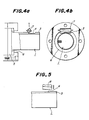
- the honeycomb structures as shown in Figs. 3a, 3b and 3d are preferably manufactured according to steps shown in Figs. 4a and 4b.
- a ceramic batch is extruded through a dies 5 having a retaining cover 6 formed at its opening with a notch or formed in a predetermined shape to form an integral honeycomb structure having a ridge 3.
- a cutting tool 7 vertically movably provided relative to the honeycomb structure 1 is lowered to a position where the cutting tool 7 is able to form a predetermined notch 4.
- the notch 4 is formed in this manner.
- the cutting tool may be rotatable.
- a depth of the notch 4 can be adjusted as will by changing the position where the cutting tool is lowered.
- the notch can be formed whose bottom is quite coincident with an outer circumferential surface of the honeycomb structure 1.
- the notch 4 is formed by means of the cutting tool 7 immediately after the extrusion of the honeycomb structure 1.
- the notch 4 can be formed by a thin wire such as piano wire without the cutting tool 7 because the extruded structure is still sufficiently soft.
- it may be cut by the cutting tool 7 or ground by a grinding wheel such as a diamond wheel.
- a pattern tool 8 having serrations is pressed against the ridge 3 at a predetermined position to form grooves by serrations of the pattern tool 8 as shown in Fig. 5.
- the notch may of course be formed by cutting or grinding.
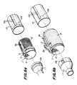
- a honeycomb structure is encircled by a sealing material or member 9 and provided with stainless wires 12 if required. Thereafter the structure is incorporated in converter cans 10 and 11. With such an arrangement, as shown in Figs. 6a and 6b any rotation of the honeycomb structure 1 about its axis is prevented by abutment of the ridge 3 against edges 9a of the sealing or holding material or member 9 and a projection 10a extending inwardly of the can 10.
- the shifting of the structure 1 in directions in parallel with the through-apertures 2 is prevented by abutment of the notch 4 of the ridge 3 against an end 9b of the sealing member 9 and projections 10b extending inwardly of the cans 10 and 11.
- the sealing member 9 is fitted in the notch 4 of the ridge 3.
- a space is formed by the honeycomb structure 1 and the cans 10 and 11 spaced by the ridge 3 and projections 10a and 10b.
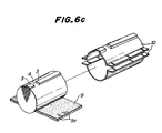
- Fig. 6c illustrates another embodiment in which a can 10 is similar in shape to the honeycomb structure 1 but slightly larger than the structure 1 and diametrically divided into two halves and a sealing member 9 is filled between the honeycomb structure 1 and the can 10.
- the sealing member 9 is formed with slits 9c correspondingly to the notch 4 of the honeycomb structure 1 so that shifting of the honeycomb structure 1 in directions parallel to the through-apertures 2 is prevented by the notch 4 and the part of the sealing member 9 between the slits 9c and fitted in the notch 4.
- the honeycomb structure 1 can be held only by the sealing member 9 without using holding means such as retains which tend to close the through-apertures, thereby saving cost for manufacturing the cans 10 and 11.
- honeycomb structures each having a 100 mm diameter, a 100 mm overall length and a through-aperture density of 46.5/cm2.
- Thicknesses of partition walls were 0.20 mm except those of Comparative example 2 which were 0.23 mm.
- Thicknesses of outer walls were about 0.3 mm.
- a honeycomb structure of Embodiment 1 according to the invention had 48 ridges 3 circumferentially arranged like petals, each having a 1 mm height and 2 mm radii of curvatures at a top and a bottom as shown in Fig. 3b. Moreover, a notch was at a location 10 mm spaced from one end surface of the honeycomb structure and had a 25 mm length, a 1 mm depth and a width over three ridges 3. A thickness of the outer wall is uniformly 0.3 mm which is different from the embodiment shown in Fig. 3b whose outer wall is varied to form the ridges.
- a honeycomb structure of Embodiment 2 according to the invention had one ridge 3 having a 1 mm height and a 20 mm width (circumferential length) and a notch 4 at a location 10 mm spaced from one end surface of the structure and having a 25 mm length and a 1 mm depth as shown in Fig. 3a.
- a honeycomb structure of Embodiment 3 according to the invention was similar to that of the Embodiment 2 with exception of a 0.5 mm height of a ridge and a 0.5 mm depth of a notch.
- a honeycomb structure of Embodiment 4 according to the invention had a ridge formed by extending an outer wall 0.3 mm radially outwardly over a 20 mm width (circumferential length) and a notch located spaced 10 mm from one end surface and having a 25 mm length and a 0.3 mm depth.
- a honeycomb structure of Embodiment 5 according to the invention had an addition to the notch of the Embodiment 4 a further notch spaced 10 mm from the other end surface and having a 25 mm length and a 0.3 mm depth.
- a honeycomb structure of Embodiment 6 according to the invention had two ridges circumferentially 45° spaced each having a 0.3 mm height and a 20 mm width and each formed at its center with a notch having a length of 50 mm.
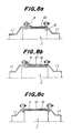
- honeycomb structures of Comparative Examples were prepared which did not have ridges 3 and notches 4 as shown in Fig. 7b.
- honeycomb structure In an external pressure strength test, aluminum plates having a thickness of about 20 mm were applied through urethane sheets having a thickness of about 0.5 mm to end surfaces of a honeycomb structure and a circumferential surface of the structure was hermetically surrounded by an urethane tube having a wall thickness of about 0.5 mm.
- the honeycomb structure was accommodated in a vessel filled with water and the pressure in the vessel is raised slowly. The pressure in the vessel when a sound was generated due to damage of the honeycomb structure was measured.
- a ceramic mat as a holding member shown in Fig. 6b was wound about a honeycomb structure and this assembly was inserted in a jig.
- the jig had an inlet whose inner diameter was larger than that of an outlet to form a tapered jig.
- the inner diameter of the outlet of the jig was substantially the same as an inner diameter of an inlet of a steel pipe or can.
- the outlet of the jig was attached to the inlet of the can and the honeycomb structure was forced into the can by means of a hydraulic ram. After the honeycomb structure was removed out of the can, an external appearance of the structure was observed.
- the ceramic mat had a thickness of 4.9 mm.
- the inner diameter of the steel pipe or can was 104.4 mm.
- a holding member shown in Table 1 was wound about a honeycomb structure and the assembly was forced into a steel pipe or can having an inner diameter forming a clearance between the honeycomb structure and a can with a flange welded thereto. Thereafter, hollow conical members were bolted to both ends of the can and tested.
- a heated gas heated at 800°C by means of a propane burner was caused to flow against the can for two minutes so as to heat the honeycomb structure. Then air at room temperature was caused to flow against the can for two minutes so as to cool the honeycomb structure.
- One cycle formed by such a heating and a cooling was repeated to 50 cycles while the can was subjected to vibrations of 0-20 g with 200 Hz. Thereafter, the hollow conical members were removed from the can from which the honeycomb structure was removed to observe an external appearance of the structure.
- honeycomb structures resisting to the heated vibration test simulated as actually used conditions are (1) those supported in directions in parallel with through-apertures as well in a hitherto used manner, (2) those including narrow clearances between the honeycomb structures and can such as 2.2 mm or supported by high holding pressure, and (3) those of the embodiments according to the invention having ridges whose heights are more than 0.5 mm.
- the honeycomb structures according to the invention can be held only on their circumferential surfaces even by low holding pressures. Even the structures having the ridges whose heights are 0.3 mm according to the invention can resist to the heated vibration test depending upon conditions to be subjected.
- the effectiveness of the ridges having the notches according to the invention has been ascertained. It has been moreover found that catalytic noble metal can be saved approximately 8% in comparison of effective volumes of catalysts between those of Embodiments according to the invention and Comparative examples of the prior art.
- the cross-sectional shape of the ceramic honeycomb structures is correctly circular in the above embodiments, it is not limited to circular and may be for example elliptical.
- the sectional shape of cells of the honeycomb structures are not limited to square as in the embodiments and the material thereof is not limited to cordierite used in the above embodiments.
- both ends of through-apertures of the honeycomb structures may of course be alternately closed.
- the honeycomb structure according to the invention comprises the ridge having the notch on its outer circumferential surface to prevent shifting in through-aperture directions and rotation about its axis, thereby enhancing the reliability of a catalyst converter incorporating the honeycomb structure therein.
- the honeycomb structure according to the invention can be incorporated in a converter without closing any ends of through-apertures so that all the catalytic noble metal carried by the honeycomb structure is effectively used for the purpose.
Landscapes
- Chemical & Material Sciences (AREA)
- Engineering & Computer Science (AREA)
- Chemical Kinetics & Catalysis (AREA)
- Ceramic Engineering (AREA)
- Mechanical Engineering (AREA)
- Structural Engineering (AREA)
- Combustion & Propulsion (AREA)
- General Engineering & Computer Science (AREA)
- Toxicology (AREA)
- Health & Medical Sciences (AREA)
- Materials Engineering (AREA)
- Organic Chemistry (AREA)
- Catalysts (AREA)
- Exhaust Gas After Treatment (AREA)
- Filtering Of Dispersed Particles In Gases (AREA)
- Exhaust Gas Treatment By Means Of Catalyst (AREA)
- Devices For Post-Treatments, Processing, Supply, Discharge, And Other Processes (AREA)
- Press-Shaping Or Shaping Using Conveyers (AREA)
Applications Claiming Priority (2)
| Application Number | Priority Date | Filing Date | Title |
|---|---|---|---|
| JP186981/88 | 1988-07-28 | ||
| JP63186981A JP2581774B2 (ja) | 1988-07-28 | 1988-07-28 | セラミックハニカム構造体およびその製造法 |
Publications (3)
| Publication Number | Publication Date |
|---|---|
| EP0353056A2 true EP0353056A2 (fr) | 1990-01-31 |
| EP0353056A3 EP0353056A3 (fr) | 1991-03-13 |
| EP0353056B1 EP0353056B1 (fr) | 1994-01-26 |
Family
ID=16198113
Family Applications (1)
| Application Number | Title | Priority Date | Filing Date |
|---|---|---|---|
| EP89307618A Expired - Lifetime EP0353056B1 (fr) | 1988-07-28 | 1989-07-27 | Structure en nid d'abeilles et son procédé de fabrication |
Country Status (5)
| Country | Link |
|---|---|
| US (1) | US5098763A (fr) |
| EP (1) | EP0353056B1 (fr) |
| JP (1) | JP2581774B2 (fr) |
| CA (1) | CA1322963C (fr) |
| DE (1) | DE68912673T2 (fr) |
Cited By (3)
| Publication number | Priority date | Publication date | Assignee | Title |
|---|---|---|---|---|
| DE10255216A1 (de) * | 2002-10-30 | 2004-05-19 | Zeuna-Stärker GmbH & Co KG | Dieselpartikelfilter für die Abgasanlage eines Fahrzeugs |
| EP1965047A1 (fr) | 2007-02-28 | 2008-09-03 | Ibiden Co., Ltd. | Corps structuré en nid d'abeille |
| EP1489274B2 (fr) † | 2002-03-04 | 2013-06-05 | Ibiden Co., Ltd. | Utilisation d'un filtre en nid d'abeilles pour la purification des gaz d'echappement |
Families Citing this family (10)
| Publication number | Priority date | Publication date | Assignee | Title |
|---|---|---|---|---|
| JP2915586B2 (ja) * | 1991-01-16 | 1999-07-05 | 日本碍子株式会社 | 抵抗調節型ヒーター |
| US5472468A (en) * | 1993-02-25 | 1995-12-05 | Sumitomo Chemical Company, Limited | Exhaust gas filter element |
| CN1272161A (zh) | 1997-09-30 | 2000-11-01 | 发射技术有限公司 | 有支承段的蜂窝体结构 |
| DE60233798D1 (de) * | 2001-07-13 | 2009-11-05 | Ngk Insulators Ltd | Wabenstrukturkörper, wabenfilter und verfahren zur herstellung des strukturkörpers und des filters |
| JP2005230680A (ja) | 2004-02-19 | 2005-09-02 | Ngk Insulators Ltd | ハニカム構造体 |
| DE102004063546A1 (de) * | 2004-12-30 | 2006-07-13 | Emitec Gesellschaft Für Emissionstechnologie Mbh | Wabenkörper mit zumindest teilweise keramischer Wabenstruktur und Aufnahme für Messfühler |
| WO2006137161A1 (fr) | 2005-06-24 | 2006-12-28 | Ibiden Co., Ltd. | Corps à structure en nid d’abeilles |
| JP4753784B2 (ja) * | 2005-06-24 | 2011-08-24 | イビデン株式会社 | ハニカム構造体、及び、排気ガス浄化装置 |
| WO2006137151A1 (fr) * | 2005-06-24 | 2006-12-28 | Ibiden Co., Ltd. | Structure en nid d’abeille et épurateur de gaz d’échapement |
| JP4885649B2 (ja) * | 2006-03-10 | 2012-02-29 | イビデン株式会社 | シート材および排気ガス浄化装置 |
Family Cites Families (16)
| Publication number | Priority date | Publication date | Assignee | Title |
|---|---|---|---|---|
| US2408164A (en) * | 1942-04-25 | 1946-09-24 | Phillips Petroleum Co | Catalyst preparation |
| US3755204A (en) * | 1970-10-22 | 1973-08-28 | Grace W R & Co | Porous ceramic-exhaust oxidation catalyst |
| US3905775A (en) * | 1972-12-12 | 1975-09-16 | Du Pont | Module |
| US3887741A (en) * | 1973-08-13 | 1975-06-03 | Corning Glass Works | Thin-walled honeycombed substrate with axial discontinuities in the periphery |
| US3983283A (en) * | 1974-03-18 | 1976-09-28 | Corning Glass Works | Honeycombed structures having open-ended cells formed by interconnected walls with longitudinally extending discontinuities |
| US4256172A (en) * | 1979-06-14 | 1981-03-17 | Ford Motor Company | Heat exchanger matrix configuration with high thermal shock resistance |
| JPS5726220A (en) * | 1980-07-24 | 1982-02-12 | Ngk Insulators Ltd | Thermal shock resisting ceramic honeycomb-type catalyzer converter |
| US4619912A (en) * | 1985-09-03 | 1986-10-28 | General Motors Corporation | Catalytic converter substrate |
| JPS62176522A (ja) * | 1986-01-27 | 1987-08-03 | Yutaka Giken:Kk | 触媒担体用ガスシ−ル装着方法 |
| JPS62179319A (ja) * | 1986-01-31 | 1987-08-06 | 三菱農機株式会社 | コンバインにおける穀粒貯留搬出装置 |
| JPH07116933B2 (ja) * | 1986-05-31 | 1995-12-18 | カルソニック株式会社 | メタル触媒コンバータ |
| US4869944A (en) * | 1987-02-12 | 1989-09-26 | Ngk Insulators, Ltd. | Cordierite honeycomb-structural body and a method for producing the same |
| DE8715289U1 (de) * | 1987-11-18 | 1988-01-14 | Emitec Gesellschaft für Emissionstechnologie mbH, 53797 Lohmar | Trägerkörper für einen katalytischen Reaktor zur Abgasreinigung |
| JP2515837B2 (ja) * | 1988-02-22 | 1996-07-10 | 日本碍子株式会社 | セラミックハニカム触媒コンバ―タ |
| KR920009120B1 (ko) * | 1988-07-06 | 1992-10-13 | 우스이 고꾸사이 산교 가부시끼가이샤 | 배기가스 정화용 촉매를 담지하기 위한 금속제 담지모체(擔持母體) |
| JPH0619793Y2 (ja) * | 1988-11-30 | 1994-05-25 | 臼井国際産業株式会社 | 排気ガス浄化装置 |
-
1988
- 1988-07-28 JP JP63186981A patent/JP2581774B2/ja not_active Expired - Lifetime
-
1989
- 1989-07-25 US US07/384,633 patent/US5098763A/en not_active Expired - Lifetime
- 1989-07-27 CA CA000606771A patent/CA1322963C/fr not_active Expired - Fee Related
- 1989-07-27 DE DE68912673T patent/DE68912673T2/de not_active Expired - Fee Related
- 1989-07-27 EP EP89307618A patent/EP0353056B1/fr not_active Expired - Lifetime
Cited By (4)
| Publication number | Priority date | Publication date | Assignee | Title |
|---|---|---|---|---|
| EP1489274B2 (fr) † | 2002-03-04 | 2013-06-05 | Ibiden Co., Ltd. | Utilisation d'un filtre en nid d'abeilles pour la purification des gaz d'echappement |
| DE10255216A1 (de) * | 2002-10-30 | 2004-05-19 | Zeuna-Stärker GmbH & Co KG | Dieselpartikelfilter für die Abgasanlage eines Fahrzeugs |
| EP1965047A1 (fr) | 2007-02-28 | 2008-09-03 | Ibiden Co., Ltd. | Corps structuré en nid d'abeille |
| US8172921B2 (en) | 2007-02-28 | 2012-05-08 | Ibiden Co., Ltd. | Honeycomb structure |
Also Published As
| Publication number | Publication date |
|---|---|
| CA1322963C (fr) | 1993-10-12 |
| JPH0240239A (ja) | 1990-02-09 |
| US5098763A (en) | 1992-03-24 |
| EP0353056A3 (fr) | 1991-03-13 |
| EP0353056B1 (fr) | 1994-01-26 |
| DE68912673T2 (de) | 1994-07-28 |
| JP2581774B2 (ja) | 1997-02-12 |
| DE68912673D1 (de) | 1994-03-10 |
Similar Documents
| Publication | Publication Date | Title |
|---|---|---|
| EP0353056B1 (fr) | Structure en nid d'abeilles et son procédé de fabrication | |
| JPH07183Y2 (ja) | セラミックハニカム構造体 | |
| AU608337B2 (en) | Catalytic converter for automotive exhaust system | |
| EP1415779B1 (fr) | Corps a structure alveolaire, filtre alveolaire et leur procede de fabrication | |
| US5329698A (en) | Method of assembling a catalytic converter | |
| US5055274A (en) | Catalytic converter and substrate support with one piece housing | |
| US8071197B2 (en) | Assembled honeycomb | |
| JP4282941B2 (ja) | ハニカム構造体及びその製造方法、並びにそれを使用した触媒体 | |
| JPH076381B2 (ja) | 触媒コンバ−タ | |
| US5149475A (en) | Method of producing a honeycomb structure | |
| JP4680437B2 (ja) | ハニカム構造体 | |
| US5380501A (en) | Exhaust gas cleaning device | |
| JPH06101466A (ja) | 内燃エンジン用触媒変換器 | |
| JPS6258009A (ja) | 触媒コンバ−タ支持体 | |
| JPH0347508A (ja) | 排ガスフイルタ | |
| KR20010023630A (ko) | 엔진실에 장착되는 촉매 지지 장치 | |
| JP4373177B2 (ja) | ハニカム構造体、その製造方法及びキャニング構造体 | |
| JP2705731B2 (ja) | ハニカム構造体 | |
| JP2515837B2 (ja) | セラミックハニカム触媒コンバ―タ | |
| JP3222954B2 (ja) | 触媒コンバータの製造方法 | |
| JP2005507043A (ja) | コア構造体装置およびその製造方法 | |
| JPH06170241A (ja) | セラミックハニカム構造体の製造方法 | |
| US8092749B2 (en) | Exhaust gas treatment device | |
| CA2009396C (fr) | Convertisseur catalytique monopiece | |
| JP2004525761A (ja) | 板状シートとその製造方法及びハニカム体 |
Legal Events
| Date | Code | Title | Description |
|---|---|---|---|
| PUAI | Public reference made under article 153(3) epc to a published international application that has entered the european phase |
Free format text: ORIGINAL CODE: 0009012 |
|
| AK | Designated contracting states |
Kind code of ref document: A2 Designated state(s): BE DE FR GB IT SE |
|
| PUAL | Search report despatched |
Free format text: ORIGINAL CODE: 0009013 |
|
| AK | Designated contracting states |
Kind code of ref document: A3 Designated state(s): BE DE FR GB IT SE |
|
| 17P | Request for examination filed |
Effective date: 19910829 |
|
| 17Q | First examination report despatched |
Effective date: 19920207 |
|
| GRAA | (expected) grant |
Free format text: ORIGINAL CODE: 0009210 |
|
| AK | Designated contracting states |
Kind code of ref document: B1 Designated state(s): BE DE FR GB IT SE |
|
| REF | Corresponds to: |
Ref document number: 68912673 Country of ref document: DE Date of ref document: 19940310 |
|
| ITF | It: translation for a ep patent filed | ||
| ET | Fr: translation filed | ||
| PLBE | No opposition filed within time limit |
Free format text: ORIGINAL CODE: 0009261 |
|
| STAA | Information on the status of an ep patent application or granted ep patent |
Free format text: STATUS: NO OPPOSITION FILED WITHIN TIME LIMIT |
|
| 26N | No opposition filed | ||
| EAL | Se: european patent in force in sweden |
Ref document number: 89307618.2 |
|
| REG | Reference to a national code |
Ref country code: GB Ref legal event code: IF02 |
|
| PGFP | Annual fee paid to national office [announced via postgrant information from national office to epo] |
Ref country code: GB Payment date: 20030717 Year of fee payment: 15 |
|
| PGFP | Annual fee paid to national office [announced via postgrant information from national office to epo] |
Ref country code: SE Payment date: 20030723 Year of fee payment: 15 Ref country code: BE Payment date: 20030723 Year of fee payment: 15 |
|
| PG25 | Lapsed in a contracting state [announced via postgrant information from national office to epo] |
Ref country code: GB Free format text: LAPSE BECAUSE OF NON-PAYMENT OF DUE FEES Effective date: 20040727 |
|
| PG25 | Lapsed in a contracting state [announced via postgrant information from national office to epo] |
Ref country code: SE Free format text: LAPSE BECAUSE OF NON-PAYMENT OF DUE FEES Effective date: 20040728 |
|
| PG25 | Lapsed in a contracting state [announced via postgrant information from national office to epo] |
Ref country code: BE Free format text: LAPSE BECAUSE OF NON-PAYMENT OF DUE FEES Effective date: 20040731 |
|
| BERE | Be: lapsed |
Owner name: *NGK INSULATORS LTD Effective date: 20040731 |
|
| EUG | Se: european patent has lapsed | ||
| GBPC | Gb: european patent ceased through non-payment of renewal fee |
Effective date: 20040727 |
|
| PG25 | Lapsed in a contracting state [announced via postgrant information from national office to epo] |
Ref country code: IT Free format text: LAPSE BECAUSE OF NON-PAYMENT OF DUE FEES;WARNING: LAPSES OF ITALIAN PATENTS WITH EFFECTIVE DATE BEFORE 2007 MAY HAVE OCCURRED AT ANY TIME BEFORE 2007. THE CORRECT EFFECTIVE DATE MAY BE DIFFERENT FROM THE ONE RECORDED. Effective date: 20050727 |
|
| PGFP | Annual fee paid to national office [announced via postgrant information from national office to epo] |
Ref country code: DE Payment date: 20070731 Year of fee payment: 19 |
|
| BERE | Be: lapsed |
Owner name: *NGK INSULATORS LTD Effective date: 20040731 |
|
| PGFP | Annual fee paid to national office [announced via postgrant information from national office to epo] |
Ref country code: FR Payment date: 20070706 Year of fee payment: 19 |
|
| PG25 | Lapsed in a contracting state [announced via postgrant information from national office to epo] |
Ref country code: DE Free format text: LAPSE BECAUSE OF NON-PAYMENT OF DUE FEES Effective date: 20090203 |
|
| REG | Reference to a national code |
Ref country code: FR Ref legal event code: ST Effective date: 20090331 |
|
| PG25 | Lapsed in a contracting state [announced via postgrant information from national office to epo] |
Ref country code: FR Free format text: LAPSE BECAUSE OF NON-PAYMENT OF DUE FEES Effective date: 20080731 |