EP0353085B1 - Dispositif comportant un double emballage flexible de sirop et une soupape de distribution - Google Patents
Dispositif comportant un double emballage flexible de sirop et une soupape de distribution Download PDFInfo
- Publication number
- EP0353085B1 EP0353085B1 EP89307688A EP89307688A EP0353085B1 EP 0353085 B1 EP0353085 B1 EP 0353085B1 EP 89307688 A EP89307688 A EP 89307688A EP 89307688 A EP89307688 A EP 89307688A EP 0353085 B1 EP0353085 B1 EP 0353085B1
- Authority
- EP
- European Patent Office
- Prior art keywords
- valve
- spout
- bag
- bags
- flow channels
- Prior art date
- Legal status (The legal status is an assumption and is not a legal conclusion. Google has not performed a legal analysis and makes no representation as to the accuracy of the status listed.)
- Expired - Lifetime
Links
- 235000020357 syrup Nutrition 0.000 title claims description 31
- 239000006188 syrup Substances 0.000 title claims description 31
- 239000007788 liquid Substances 0.000 claims description 18
- 235000013361 beverage Nutrition 0.000 claims description 10
- 230000008878 coupling Effects 0.000 claims description 6
- 238000010168 coupling process Methods 0.000 claims description 6
- 238000005859 coupling reaction Methods 0.000 claims description 6
- 230000003213 activating effect Effects 0.000 claims description 5
- 230000009977 dual effect Effects 0.000 description 2
- 238000007789 sealing Methods 0.000 description 2
- 229910001220 stainless steel Inorganic materials 0.000 description 2
- 239000010935 stainless steel Substances 0.000 description 2
- 235000005911 diet Nutrition 0.000 description 1
- 230000037213 diet Effects 0.000 description 1
- 239000000428 dust Substances 0.000 description 1
- 238000003780 insertion Methods 0.000 description 1
- 230000037431 insertion Effects 0.000 description 1
- 238000009434 installation Methods 0.000 description 1
- 235000020374 simple syrup Nutrition 0.000 description 1
Images


Classifications
-
- B—PERFORMING OPERATIONS; TRANSPORTING
- B67—OPENING, CLOSING OR CLEANING BOTTLES, JARS OR SIMILAR CONTAINERS; LIQUID HANDLING
- B67D—DISPENSING, DELIVERING OR TRANSFERRING LIQUIDS, NOT OTHERWISE PROVIDED FOR
- B67D1/00—Apparatus or devices for dispensing beverages on draught
-
- B—PERFORMING OPERATIONS; TRANSPORTING
- B67—OPENING, CLOSING OR CLEANING BOTTLES, JARS OR SIMILAR CONTAINERS; LIQUID HANDLING
- B67D—DISPENSING, DELIVERING OR TRANSFERRING LIQUIDS, NOT OTHERWISE PROVIDED FOR
- B67D3/00—Apparatus or devices for controlling flow of liquids under gravity from storage containers for dispensing purposes
- B67D3/04—Liquid-dispensing taps or cocks adapted to seal and open tapping holes of casks, e.g. for beer
-
- B—PERFORMING OPERATIONS; TRANSPORTING
- B67—OPENING, CLOSING OR CLEANING BOTTLES, JARS OR SIMILAR CONTAINERS; LIQUID HANDLING
- B67D—DISPENSING, DELIVERING OR TRANSFERRING LIQUIDS, NOT OTHERWISE PROVIDED FOR
- B67D1/00—Apparatus or devices for dispensing beverages on draught
- B67D1/0042—Details of specific parts of the dispensers
- B67D1/0078—Ingredient cartridges
-
- B—PERFORMING OPERATIONS; TRANSPORTING
- B67—OPENING, CLOSING OR CLEANING BOTTLES, JARS OR SIMILAR CONTAINERS; LIQUID HANDLING
- B67D—DISPENSING, DELIVERING OR TRANSFERRING LIQUIDS, NOT OTHERWISE PROVIDED FOR
- B67D1/00—Apparatus or devices for dispensing beverages on draught
- B67D1/0042—Details of specific parts of the dispensers
- B67D1/0078—Ingredient cartridges
- B67D1/0079—Ingredient cartridges having their own dispensing means
-
- B—PERFORMING OPERATIONS; TRANSPORTING
- B67—OPENING, CLOSING OR CLEANING BOTTLES, JARS OR SIMILAR CONTAINERS; LIQUID HANDLING
- B67D—DISPENSING, DELIVERING OR TRANSFERRING LIQUIDS, NOT OTHERWISE PROVIDED FOR
- B67D3/00—Apparatus or devices for controlling flow of liquids under gravity from storage containers for dispensing purposes
- B67D3/0019—Apparatus or devices for controlling flow of liquids under gravity from storage containers for dispensing purposes using ingredient cartridges
-
- Y—GENERAL TAGGING OF NEW TECHNOLOGICAL DEVELOPMENTS; GENERAL TAGGING OF CROSS-SECTIONAL TECHNOLOGIES SPANNING OVER SEVERAL SECTIONS OF THE IPC; TECHNICAL SUBJECTS COVERED BY FORMER USPC CROSS-REFERENCE ART COLLECTIONS [XRACs] AND DIGESTS
- Y10—TECHNICAL SUBJECTS COVERED BY FORMER USPC
- Y10T—TECHNICAL SUBJECTS COVERED BY FORMER US CLASSIFICATION
- Y10T137/00—Fluid handling
- Y10T137/8593—Systems
- Y10T137/87153—Plural noncommunicating flow paths
Definitions
- This invention relates to beverage dispensing systems and in particular to a binary syrup system in which the syrup is provided in two separate containers holding two different syrup components rather than being provided in one single container. This allows certain component(s) to be separated from certain other component(s), until just prior to dispensing, when the two components are combined to form the complete syrup.
- a larger number of beverage dispensing systems are known for use with both sugar syrups and diet syrups, and for use with various types of syrup containers such as pressurized tanks (figals) and non-pressurized plastic bags (bag-in-box) used in conjunction with syrup pumps.
- the known bag-in-box bags include a spout and a valve connected to the spout for opening or closing liquid communication with the syrup in the bag.
- a quick-disconnect coupling is attached to the bag valve to open it and to allow syrup to be fed to a beverage dispenser by means of a syrup pump connected between the bag and the dispenser.
- EP-A-0134142 discloses a bag valve for a binary syrup bag for use in beverage dispensing comprising: a valve body; and a pair of separate liquid flow channels through said body.
- the present invention is characterised in that there is provided: a spring retainer connector below said body, said flow channels being provided in said connector; said connector being connected to said body by a snap fit with a liquid-tight interference fit therebetween; a poppet valve in each said channels between said body and said connector, a spring in each of said channels in said connector for biasing said poppet valves closed against a valve seat in said body, and a poppet activating pin attached to each poppet valve and extending upwardly through said channel in said body, said poppet valves being in a normally closed position when no coupler is attached to said valve; and said body including means for coupling a hose coupler to said valve.
- the valve is connected to a bag spout, said valve having said pair of separate liquid flow channels therethrough in liquid communication with a respective one of corresponding spout flow channels.
- the valve includes means for connecting it to a syrup hose coupler, and attachment of the coupler causes the poppet valves to open.
- a pair of dip strips is preferably connected to the spout, with one in each bag.
- not only the connection between the two parts of the valve but also that between the valve and the spout are snap-in interference fits to provide easy liquid-tight connections that can be made by automatic machinery.
- a quick-disconnect coupling that can be permanently installed in the retail outlet and which is attachable to the valve to move the valve to its open position to allow each of the two syrup components to be dispensed from the two bags and fed to the beverage dispenser.
- Figs. 1 to 5 show the preferred embodiment of the present invention of a binary syrup system 10 including a pair of bag-in-box syrup bags 12 and 14 each holding a different component of the syrup, a metering device 16 for ensuring the proper ratio of the two components being fed to a dispenser, a syrup pump 18 and a beverage dispenser 20.
- the metering device includes two inlet ports, one for each of the syrup components, and a single outlet port for the complete syrup formed when the two components are combined in the correct ratio, for example, 1:1.
- the two bags 12 and 14 are contained in a single box 22.
- a well known bag-in-box system for syrup now uses one single five gallon bag in a box and the present invention preferably uses two two and one-half gallon bags 12 and 14 in a single box 22.
- Fig. 2 shows the two bags 12 and 14 and a spout 24 connected to both bags 12 and 14 with a dip strip 26 connected to the spout and contained in bag 12 and a dip strip 28 connected to the spout and contained in bag 14.
- Fig. 3 also shows the spout 24 and the manner of connecting the spout to the two bags 12 and 14.
- Two bags are preferably formed from one pair of bag walls, one of the walls having a single opening therethrough.
- the spout flange 30 is preferably heat sealed to said one wall and a liquid-tight seam 32 is used to form a single larger bag into the two separate bags 12 and 14.
- the seam is interrupted at the spout where the other wall is heat sealed to a bottom edge of a wall 34 which extends diametrically across the bottom opening in the spout 24.
- the two dip strips 26 and 28 are connected to a single ring 36 which snaps into place in the bottom opening of the spout 24.
- Other arrangements can be used for connecting dip strips to the spout and other shapes and sized of dip strips can be used.
- the present invention can be used without any dip strips.
- the valve 40 of the present invention will now be described with reference to Figs. 3, 4 and 5.
- the valve 40 provides for two separate liquid channels in one valve structure. One end of each channel is open to one of the bags. The other end of each channel is closed by a poppet valve which is activated (opened) when a coupler is attached to the open side of the valve.
- the valve includes the following components.
- a valve body 42 which incorporates the seats for the two poppet valves 52 and 56.
- the open end of the valve body has been designed to receive the coupler 80 which has two cylinders 66 and 68 which fit in the two sockets 67 and 69 containing the poppet activating pins 71 and 73.
- External thread 86 is provided to receive a screw cap to protect the valve during storage and shipping.
- the other end of the valve body has been designed to receive the spring retainer/connector 44 to the spout.
- the outside of the cylindrical section of the valve body has been designed to provide two click stops inside the spout. The first one for temporary insertion of the valve body in the bag spout. This arrangement allows for use of the valve as a temporary "dust cap" until each side of the dual bag is ready to be filled.
- the second click stop is for permanent installation of the valve after filling.
- the valve 40 also includes the two poppet valves 52 and 56 with integral activating pins 71 and 73.
- a pair of springs 50 and 54 bias the poppets against the valve seats.
- the spring retainer/connector 44 to the spout contains the springs 50 and 54 providing sealing pressure for each of the two poppets.
- the connector 44 is held in place by a groove 92 in the valve body.
- Each of the two flow channels in the connector 44 containing a spring is locked into the valve body with a snap in interference fit seal.
- the same sealing arrangement is used to seal the other end of each channel into a corresponding socket 94 and 96 in the spout 24.
- valve body, the connector, the two springs and two poppet valves, when assembled together are the valve.
- the spout is permanently sealed to the bags.
- Each bag compartment is connected to one of the two channels in the valve.
- Fig. 3 shows the valve 40 in its closed position in solid lines and in open position in dotted or phantom lines.
- Fig. 3 also shows the coupler 80 including a pair of stainless steel barb connectors 81 and 82 connected to hoses 83 and 84 (the hoses are not transparent but are shown as such for clarity).
- the valve 40 includes external screw threads 86 that mate with internal screw threads 87 in the coupler 80.
- the quick-disconnect coupler 80 is simply screwed on to the valve 40 to open the valve allowing syrup to be pumped out of the bags 12 and 14.
- the coupler 80 includes the connectors 81 and 82, preferably of stainless steel molded to a central element 98, the nut 99 that can rotate relative to the element 98, and the two cylinders 66 and 68 with their spring loaded caps 72 and 76 that contact and move the poppet activating pins 71 and 73.
- the two cylinders are attached or made integrally with the element 98.
- the caps 72 and 76 have flow passages therethrough. As the coupler 80 moves downwardly (as viewed in Fig.
- the spring retainer/connector 44 is attached to the body 42 by a snap-in, liquid-tight interference fit at 108 and also by the groove 92.
- the lower end (as viewed in Fig. 3) of the two cylinders 47 and 49 snap-fit in a liquid-tight interference fit to the upper end of the two cylinders 102 and 104 that extend up from a lower wall 106 of the spout.
- the body 42 is snap-fit to the spout at 41 with an interference although a liquid-tight fit is not necessary at 41.
- the connector 44 has two flow channels 46 and 48 therethrough in cylinders 47 and 49 which retain the springs 50 and 54.
- the two cylinders 66 and 68 in the coupler 80 have two flow channels 62 and 64 respectively and retain the springs 70 and 74 respectively.
- valve body and connector and of the valve into the spout allow for ease of assembly and also of automated assembly, if desired.
- valve When it is desired to fill the bags, the valve is removed from the spout, the bags filled, and then the spout is reinserted and this time for a permanent attachment.
- the various snap-fits are made possible because of the use of circular cross-section passages and circular retaining flanges.
- a keyway is provided.
- a rib 110 in the valve body is received in a slot 112 in the plate 114 connected to the cylinders 66 and 68.
- Fig. 5 shows guide ribs 116 for the pins 71 and 73. It is understood that chamfered or tapered edges are provided at all snap-fit areas.
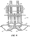
- Fig. 6 shows an alternative embodiment of a valve and coupler according to another embodiment of the present invention.
Landscapes
- Engineering & Computer Science (AREA)
- Mechanical Engineering (AREA)
- Devices For Dispensing Beverages (AREA)
- Packages (AREA)
- Non-Alcoholic Beverages (AREA)
Claims (12)
- Clapet de sac pour un double sac à sirop à utiliser dans un distributeur de boisson, comprenant :
un corps de clapet (42) ; et
une paire de canaux séparés d'écoulement de liquide (46,48) à travers ledit corps (42),
caractérise en ce que sont prévus :
un connecteur de retenue à ressort (44) au dessous dudit corps (42), lesdit canaux d'écoulement étant ménagés dans ledit connecteur (44);
ledit connecteur (44) étant connecté audit corps (42) par encliquetage, avec interposition d'un joint imperméable à ajustement serré (108);
une soupape (52,56) dans chacun desdits canaux, entre ledit corps (42) et ledit connecteur (44), un ressort (50,54) dans chacun desdits canaux (46,48) dudit connecteur (44), pour repousser lesdites soupapes (52,56) étroitement contre un siège dudit corps (42), et un ergot d'activation (71,73) de soupapes, fixé sur chaque soupape (52,56) et s'étendant vers le haut à travers ledit canal dans ledit corps, lesdites soupapes (52,56) étant dans une position normale fermée lorsqu'aucun coupleur (80) n'est fixé sur ledit clapet (40) ; et
ledit corps (42) incluant des moyens permettant d'accoupler un coupleur pour tuyau (80) audit clapet. - Clapet de sac selon la revendication 1, dans lequel ledit corps (42) et ledit connecteur (44) incluent chacun une bride de retenue (41) circulaire encliquetable, à utiliser pour une connexion à un orifice de sac (24).
- Sac double à sirop (12,14) à utiliser dans un distributeur de boisson, comprenant :
une paire de sacs (12,14) séparés, flexibles et repliables, chacun ayant une ouverture unique de liquide, au sein d'une seule boîte à sac (22) ;
un orifice (24) unique au sein duquel est ménagée une paire de canaux séparés d'écoulement de liquide, connectés aux deux desdits sacs (12,14) avec l'un desdits canaux d'écoulement en communication par le liquide avec ladite ouverture de l'un desdits sacs (12,14) et l'autre canal d'écoulement en communication par le liquide avec ladite ouverture de l'autre desdits sacs ; et
un clapet (40) selon la revendication 1 ou 2, ledit clapet (40) étant connecté audit orifice (24), ladite paire de canaux séparés d'écoulement de liquide (46,48) du clapet étant en communication par le liquide avec l'un respectivement desdits canaux d'écoulement, ledit clapet (40) étant connecté audit orifice (24) par l'intermédiaire d'un joint à ajustement serré (41) encliquetable et imperméable. - Sac selon la revendication 3, comprenant un coupleur à déconnexion rapide (80) fixé audit clapet (40), et des moyens permettant de déplacer ledit clapet (40) à partir d'une position fermée vers une position ouverte, lorsque ledit coupleur (80) est fixé audit clapet (40).
- Sac selon l'une des revendications 3 ou 4, comprenant une unité unique (26,28,36) connectée audit orifice (24) et incluant une paire de bandes inclinées séparées (26,28), chacune étant positionnée à l'intérieur de chacun desdits sacs (12,14).
- Sac selon la revendication 3, 4 ou 5, dans lequel ladite paire de sacs (12,14) est formée à partir d'une paire unique de parois de sac incluant une jonction imperméable (32) le long du milieu de ladite paire de parois de sac, une ouverture d'orifice unique dans l'une desdites parois de sac directement en relation avec ladite jonction (32), ladite jonction (32) étant interrompue au niveau dudit orifice (24), et ladite autre paroi de sac étant scellée à un bord inférieur d'une paroi diamétralement opposée (34) dudit orifice (24).
- Double système à sirop (10) pour distributeur de boisson, à partir de deux récipients (12,14) séparés de sirop, chacun contenant un composant de sirop différent, comprenant :a) une paire de sacs à sirop (12,14) au sein d'une seule boîte à sacs (22) ;b) un orifice (24) unique connecté en partie à l'un desdit sacs (12,14) et en partie à l'autre desdits sacs (12,14) ;c) un clapet de sac (40) selon la revendication 1 ou 2, ledit clapet (40) étant connecté audit orifice (24) et étant déplaçable entre des positions ouvertes et fermées ; etd) ledit orifice (24) ayant une paire de canaux séparés d'écoulement de liquide ménagé en son sein, l'un desdits canaux d'écoulement étant en communication par l'écoulement de liquide avec l'intérieur de l'un desdits sacs (12) et l'autre desdits canaux d'écoulement étant en communication par l'écoulement de liquide avec l'intérieur de l'autre desdits sacs (14), et les canaux séparés d'écoulement de liquide (46,48) du clapet (40) étant en communication par le liquide avec l'un respectivement desdits canaux d'écoulement, le clapet (40) et l'orifice (24) étant connectés entre eux par un joint à ajustement serré (41) encliquetable, et lesdits canaux d'écoulement dans ledit orifice étant scellés à ceux dudit clapet, sous l'action du joint à ajustement serré interposé entre le clapet (40) et l'orifice (24).
- Système selon la revendication 7, dans lequel ladite paire de sacs comprend un sac unique avec une jonction (32) imperméable le long du milieu de ce dernier, séparant ledit sac unique en deux sacs séparés (12,14), et dans lequel ledit orifice (24) est situé sur ladite jonction (32).
- Système selon la revendication 7 ou 8, dans lequel lesdits canaux d'écoulement (46,48) présentent tous des sections transversales circulaires.
- Système selon l'une quelconque des revendications 7 à 9, dans lequel ledit clapet (40) inclus un filetage externe (86 ) permettant la connexion à un coupleur pour tuyau (80) à déconnexion rapide.
- Système selon l'une quelconque des revendications précédentes, comprenant un coupleur pour tuyau (80) connectable audit clapet (40), ledit coupleur pour tuyau (80) comprenant des moyens permettant de déplacer ledit clapet (40) à partir de sa position fermée jusqu'à sa position ouverte.
- Système selon la revendication 10 ou 11 dans lequel est prévue une rainure de clavette entre ledit coupleur (80) et le clapet (40), de sorte que les canaux d'écoulement respectifs du coupleur (80) et du clapet (40) soient alignés.
Applications Claiming Priority (2)
| Application Number | Priority Date | Filing Date | Title |
|---|---|---|---|
| US07/224,645 US4913316A (en) | 1988-07-27 | 1988-07-27 | Binary syrup system bag and valve |
| US224645 | 1988-07-27 |
Publications (2)
| Publication Number | Publication Date |
|---|---|
| EP0353085A1 EP0353085A1 (fr) | 1990-01-31 |
| EP0353085B1 true EP0353085B1 (fr) | 1994-11-30 |
Family
ID=22841549
Family Applications (1)
| Application Number | Title | Priority Date | Filing Date |
|---|---|---|---|
| EP89307688A Expired - Lifetime EP0353085B1 (fr) | 1988-07-27 | 1989-07-27 | Dispositif comportant un double emballage flexible de sirop et une soupape de distribution |
Country Status (12)
| Country | Link |
|---|---|
| US (1) | US4913316A (fr) |
| EP (1) | EP0353085B1 (fr) |
| JP (1) | JPH02152689A (fr) |
| KR (1) | KR910002704A (fr) |
| AR (1) | AR243843A1 (fr) |
| AT (1) | ATE114609T1 (fr) |
| AU (1) | AU627479B2 (fr) |
| BR (1) | BR8903719A (fr) |
| CA (1) | CA1319653C (fr) |
| DE (1) | DE68919572D1 (fr) |
| MX (1) | MX167294B (fr) |
| ZA (1) | ZA895534B (fr) |
Cited By (1)
| Publication number | Priority date | Publication date | Assignee | Title |
|---|---|---|---|---|
| US7694852B2 (en) | 2002-07-30 | 2010-04-13 | Nestec S.A. | System for dispensing a liquid substance |
Families Citing this family (48)
| Publication number | Priority date | Publication date | Assignee | Title |
|---|---|---|---|---|
| US4998990A (en) * | 1988-12-20 | 1991-03-12 | The Coca-Cola Company | Collapsible bag with evacuation passageway and method for making the same |
| US5064101A (en) * | 1989-10-31 | 1991-11-12 | The Coca-Cola Company | Five gallon nestable plastic syrup container |
| US5242085A (en) * | 1990-12-17 | 1993-09-07 | The Coca-Cola Company | Liquid container system |
| US5381927A (en) * | 1990-12-17 | 1995-01-17 | The Coca-Cola Company | Method of dispensing from a liquid container system |
| US5147071A (en) * | 1991-04-09 | 1992-09-15 | The Coca-Cola Company | Collapsible bag with evacuation passageway and method for making the same |
| US5341957A (en) * | 1993-01-08 | 1994-08-30 | Sizemore Sean S | Cup-type vending system and method for dispensing beverages |
| US5651482A (en) * | 1993-01-08 | 1997-07-29 | Sizemore; Sean S. | Syrup delivery kit for vending system |
| US5495965A (en) * | 1994-04-25 | 1996-03-05 | Aptar Group, Inc. | Dip tube for hand operated dispensing device |
| US5518151A (en) * | 1994-04-25 | 1996-05-21 | Aptar Group, Inc. | Dip tube for hand operated dispensing device |
| WO1999032173A1 (fr) * | 1997-12-19 | 1999-07-01 | United States Surgical Corporation | Systeme de distribution a deux elements |
| US6196265B1 (en) | 1998-07-29 | 2001-03-06 | Wec Co. | Multi-line fluid connector |
| US6619319B1 (en) | 1998-07-29 | 2003-09-16 | Woods Equipment Company | Multi-line fluid connector |
| US6179173B1 (en) | 1998-10-30 | 2001-01-30 | The Coca-Cola Company | Bib spout with evacuation channels |
| US7597922B2 (en) * | 1999-05-18 | 2009-10-06 | Nestec S.A. | System for dispensing a liquid beverage concentrate |
| US6756069B2 (en) * | 1999-05-18 | 2004-06-29 | Nestec S.A. | System and method for dispensing a liquid beverage concentrate |
| US7194847B2 (en) * | 1999-09-09 | 2007-03-27 | Sashco, Inc. | Method of filling dispensing cartridges having collapsible packages |
| WO2001017869A1 (fr) * | 1999-09-09 | 2001-03-15 | Sashco, Inc. | Emballage destine a des materiaux a composants multiples et procedes de fabrication correspondant |
| US7017781B2 (en) * | 2000-04-13 | 2006-03-28 | Dr Pepper/Seven-Up, Inc. | Collapsible container for liquids |
| US20040221407A1 (en) * | 2001-07-30 | 2004-11-11 | Tennant Company | Cleaning liquid dispensing system |
| US20050217062A1 (en) * | 2001-07-30 | 2005-10-06 | Tennant Company | Air purging of a liquid dispensing system of a surface cleaner |
| US6671925B2 (en) * | 2001-07-30 | 2004-01-06 | Tennant Company | Chemical dispenser for a hard floor surface cleaner |
| US8051861B2 (en) * | 2001-07-30 | 2011-11-08 | Tennant Company | Cleaning system utilizing purified water |
| US7051399B2 (en) * | 2001-07-30 | 2006-05-30 | Tennant Company | Cleaner cartridge |
| US20030196411A1 (en) * | 2002-04-19 | 2003-10-23 | Schroeder Alfred A. | Flexible packaging |
| US8052628B1 (en) | 2002-10-08 | 2011-11-08 | Vitalwear, Inc. | Spinal column brace for a contrast therapy system |
| US7694693B1 (en) | 2002-10-08 | 2010-04-13 | Vitalwear, Inc. | Mixing valve for a contrast therapy system |
| US8425579B1 (en) | 2002-10-08 | 2013-04-23 | Vitalwear, Inc. | Therapeutic knee brace for a contrast therapy system |
| US6968669B2 (en) * | 2002-11-06 | 2005-11-29 | Lancer Partnership Ltd. | Flexible packaging |
| US7658205B1 (en) * | 2002-12-19 | 2010-02-09 | Vitalwear, Inc. | Systems for a fluid circuit coupler |
| US8028365B2 (en) * | 2003-09-02 | 2011-10-04 | Tennant Company | Hard and soft floor cleaning tool and machine |
| JP2008509356A (ja) * | 2004-08-06 | 2008-03-27 | ネルコアー ピューリタン ベネット インコーポレイテッド | 流体の貯蔵および送達デバイス |
| JP2008519657A (ja) | 2004-11-12 | 2008-06-12 | テナント・カンパニー | 可動フロアクリーナデータ通信 |
| US20060165020A1 (en) * | 2004-11-24 | 2006-07-27 | Allen Schultz | Audio conference system |
| WO2006110459A2 (fr) * | 2005-04-07 | 2006-10-19 | Tennant Company | Machine de nettoyage de surface de sols durs et mous |
| MX2007013798A (es) * | 2005-05-05 | 2008-01-21 | Tennant Co | Maquina para barrido y fregado de pisos. |
| US8584294B2 (en) * | 2005-10-21 | 2013-11-19 | Tennant Company | Floor cleaner scrub head having a movable disc scrub member |
| US8091864B2 (en) * | 2005-12-20 | 2012-01-10 | Ds Smith Plastics Limited | Valve for a fluid flow connector having an overmolded plunger |
| CA2898211C (fr) | 2007-05-11 | 2018-01-02 | Lawrence Dull | Systemes, composants et procedes pour distribuer des substances liquides |
| WO2011015902A1 (fr) * | 2009-08-06 | 2011-02-10 | Sodastream Industries Ltd. | Tige d'activation pour distributeurs de boisson |
| WO2011054402A1 (fr) * | 2009-11-09 | 2011-05-12 | B.V. Cindy J. | Dispositifs d'infusion de boissons |
| CN105392706B (zh) * | 2013-05-17 | 2019-07-16 | 利奎-保克斯公司 | 在可皱缩袋中的柔性安装的排出构件 |
| WO2017062361A1 (fr) | 2015-10-06 | 2017-04-13 | Focus Evolution LLC | Systèmes de distribution de boissons alcoolisées |
| US11078067B2 (en) * | 2016-03-03 | 2021-08-03 | Verdesian Life Sciences U.S., Llc | Inoculant direct injection system |
| US11274031B2 (en) * | 2016-03-03 | 2022-03-15 | Verdesian Life Sciences U.S., Llc | Inoculant direct injection system |
| US10399844B1 (en) * | 2017-03-27 | 2019-09-03 | Rodney Laible | Bag insert |
| US12103841B1 (en) | 2022-03-22 | 2024-10-01 | Bar Evolution Llc | Connector assembly |
| US12297025B2 (en) | 2022-07-27 | 2025-05-13 | Bar Evolution Llc | Box for receipt of bags containing liquid |
| US12497281B1 (en) | 2022-11-11 | 2025-12-16 | Bar Evolution Llc | System for controllably connecting a beverage dispensing package to a supply line |
Citations (1)
| Publication number | Priority date | Publication date | Assignee | Title |
|---|---|---|---|---|
| EP0171870A1 (fr) * | 1984-04-04 | 1986-02-19 | Marley Technical Products (Proprietary) Limited | Robinets de distribution de liquide |
Family Cites Families (19)
| Publication number | Priority date | Publication date | Assignee | Title |
|---|---|---|---|---|
| DE102668C (fr) * | ||||
| US2198524A (en) * | 1938-07-01 | 1940-04-23 | Laval Separator Co De | Device for delivering measured quantities of liquids |
| US2359648A (en) * | 1943-03-03 | 1944-10-03 | Green S Fuel Inc | Unitary coupling for plural conduits |
| US3206074A (en) * | 1962-09-18 | 1965-09-14 | Colgate Palmolive Co | Multiple compartmented dispensing package |
| US3197071A (en) * | 1962-12-03 | 1965-07-27 | Colgate Palmolive Co | Multiple compartment dispenser |
| US3177896A (en) * | 1963-03-29 | 1965-04-13 | Schulz Tool & Mfg Co | Quick disconnect full-flow couplings and unitary socket therefor |
| US3323682A (en) * | 1965-10-06 | 1967-06-06 | Chem Dev Corp | Disposable cartridge for gun-type dispensers |
| US4286636A (en) * | 1979-07-19 | 1981-09-01 | The Coca-Cola Company | Dip tube and valve with quick-disconnect coupling for a collapsible container |
| US4316557A (en) * | 1979-12-17 | 1982-02-23 | Sunkist Growers, Inc. | Beverage dispenser with removable tank connection means |
| US4549675A (en) * | 1982-09-07 | 1985-10-29 | The Cornelius Co. | Beverage dispensing valve |
| US4528180A (en) * | 1983-03-01 | 1985-07-09 | Schaeffer Hans A | Dental preparation, article and method for storage and delivery thereof |
| GB8322026D0 (en) * | 1983-08-16 | 1983-09-21 | Unilever Plc | Bag-in-box |
| US4524458A (en) * | 1983-11-25 | 1985-06-18 | Pongrass Robert G | Moisture responsive stiffening members for flexible containers |
| US4564132A (en) * | 1984-02-24 | 1986-01-14 | Scholle Corporation | Fluid dispensing assembly |
| US4601410A (en) * | 1984-03-29 | 1986-07-22 | Liqui-Box Corporation | Collapsed bag with evacuation channel form unit |
| US4736872A (en) * | 1986-03-18 | 1988-04-12 | National Patent Development Corp. | Disposable tint pack assembly for contact lens tinting |
| US4708266A (en) * | 1986-03-21 | 1987-11-24 | The Coca-Cola Company | Concentrate dispensing system for a post-mix beverage dispenser |
| US4796788A (en) * | 1987-08-26 | 1989-01-10 | Liqui-Box Corporation | Bag-in-box packaging and dispensing of substances which will not readily flow by gravity |
| US4838457A (en) * | 1988-05-09 | 1989-06-13 | Swahl James C | Lotion blending and dispensing unit |
-
1988
- 1988-07-27 US US07/224,645 patent/US4913316A/en not_active Ceased
-
1989
- 1989-07-20 ZA ZA895534A patent/ZA895534B/xx unknown
- 1989-07-24 AR AR89314491A patent/AR243843A1/es active
- 1989-07-25 CA CA000606529A patent/CA1319653C/fr not_active Expired - Fee Related
- 1989-07-26 KR KR1019890010584A patent/KR910002704A/ko not_active Withdrawn
- 1989-07-26 JP JP1191584A patent/JPH02152689A/ja active Pending
- 1989-07-26 BR BR898903719A patent/BR8903719A/pt not_active IP Right Cessation
- 1989-07-27 EP EP89307688A patent/EP0353085B1/fr not_active Expired - Lifetime
- 1989-07-27 MX MX016948A patent/MX167294B/es unknown
- 1989-07-27 AT AT89307688T patent/ATE114609T1/de not_active IP Right Cessation
- 1989-07-27 AU AU39031/89A patent/AU627479B2/en not_active Ceased
- 1989-07-27 DE DE68919572T patent/DE68919572D1/de not_active Expired - Lifetime
Patent Citations (1)
| Publication number | Priority date | Publication date | Assignee | Title |
|---|---|---|---|---|
| EP0171870A1 (fr) * | 1984-04-04 | 1986-02-19 | Marley Technical Products (Proprietary) Limited | Robinets de distribution de liquide |
Cited By (1)
| Publication number | Priority date | Publication date | Assignee | Title |
|---|---|---|---|---|
| US7694852B2 (en) | 2002-07-30 | 2010-04-13 | Nestec S.A. | System for dispensing a liquid substance |
Also Published As
| Publication number | Publication date |
|---|---|
| DE68919572D1 (de) | 1995-01-12 |
| BR8903719A (pt) | 1990-03-20 |
| AU3903189A (en) | 1990-02-15 |
| US4913316A (en) | 1990-04-03 |
| JPH02152689A (ja) | 1990-06-12 |
| KR910002704A (ko) | 1991-02-26 |
| ZA895534B (en) | 1991-03-27 |
| ATE114609T1 (de) | 1994-12-15 |
| AU627479B2 (en) | 1992-08-27 |
| AR243843A1 (es) | 1993-09-30 |
| EP0353085A1 (fr) | 1990-01-31 |
| CA1319653C (fr) | 1993-06-29 |
| MX167294B (es) | 1993-03-15 |
Similar Documents
| Publication | Publication Date | Title |
|---|---|---|
| EP0353085B1 (fr) | Dispositif comportant un double emballage flexible de sirop et une soupape de distribution | |
| USRE33969E (en) | Binary syrup system bag and valve | |
| US4564132A (en) | Fluid dispensing assembly | |
| EP0657005B1 (fr) | Soupape de distribution | |
| US10906716B2 (en) | Spout-connector assembly for fluid dispensing from flexible bags | |
| EP2057403B1 (fr) | Raccord de soupape à tiroir et collier | |
| US5709244A (en) | Collapsible container connector | |
| EP0790957B1 (fr) | Soupape a fermeture automatique pour carton outre | |
| US7487951B2 (en) | Double slider valve fitment | |
| US9862588B2 (en) | Fitment for dispensing fluids from a flexible container | |
| IE54446B1 (en) | Beverage dispenser | |
| US6953070B1 (en) | Dispenser valve with push-to-open spout | |
| AU2862395A (en) | Valve for bag-in-box | |
| WO2010100435A1 (fr) | Ensemble raccord pour la distribution de fluide | |
| EP4186813A1 (fr) | Pièce de raccordement pour un embout de remplissage d'un distributeur et récipient pourvu de la pièce de raccordement | |
| AU688180C (en) | A self-sealing bag valve |
Legal Events
| Date | Code | Title | Description |
|---|---|---|---|
| PUAI | Public reference made under article 153(3) epc to a published international application that has entered the european phase |
Free format text: ORIGINAL CODE: 0009012 |
|
| AK | Designated contracting states |
Kind code of ref document: A1 Designated state(s): AT BE CH DE ES FR GB GR IT LI LU NL SE |
|
| 17P | Request for examination filed |
Effective date: 19900521 |
|
| 17Q | First examination report despatched |
Effective date: 19920408 |
|
| GRAA | (expected) grant |
Free format text: ORIGINAL CODE: 0009210 |
|
| AK | Designated contracting states |
Kind code of ref document: B1 Designated state(s): AT BE CH DE ES FR GB GR IT LI LU NL SE |
|
| PG25 | Lapsed in a contracting state [announced via postgrant information from national office to epo] |
Ref country code: IT Free format text: LAPSE BECAUSE OF FAILURE TO SUBMIT A TRANSLATION OF THE DESCRIPTION OR TO PAY THE FEE WITHIN THE PRESCRIBED TIME-LIMIT;WARNING: LAPSES OF ITALIAN PATENTS WITH EFFECTIVE DATE BEFORE 2007 MAY HAVE OCCURRED AT ANY TIME BEFORE 2007. THE CORRECT EFFECTIVE DATE MAY BE DIFFERENT FROM THE ONE RECORDED. Effective date: 19941130 Ref country code: BE Effective date: 19941130 Ref country code: CH Effective date: 19941130 Ref country code: AT Effective date: 19941130 Ref country code: LI Effective date: 19941130 Ref country code: GR Free format text: LAPSE BECAUSE OF FAILURE TO SUBMIT A TRANSLATION OF THE DESCRIPTION OR TO PAY THE FEE WITHIN THE PRESCRIBED TIME-LIMIT Effective date: 19941130 Ref country code: NL Effective date: 19941130 Ref country code: ES Free format text: THE PATENT HAS BEEN ANNULLED BY A DECISION OF A NATIONAL AUTHORITY Effective date: 19941130 Ref country code: FR Effective date: 19941130 |
|
| REF | Corresponds to: |
Ref document number: 114609 Country of ref document: AT Date of ref document: 19941215 Kind code of ref document: T |
|
| REF | Corresponds to: |
Ref document number: 68919572 Country of ref document: DE Date of ref document: 19950112 |
|
| PG25 | Lapsed in a contracting state [announced via postgrant information from national office to epo] |
Ref country code: SE Effective date: 19950228 |
|
| PG25 | Lapsed in a contracting state [announced via postgrant information from national office to epo] |
Ref country code: DE Effective date: 19950301 |
|
| REG | Reference to a national code |
Ref country code: CH Ref legal event code: PL |
|
| EN | Fr: translation not filed | ||
| NLV1 | Nl: lapsed or annulled due to failure to fulfill the requirements of art. 29p and 29m of the patents act | ||
| PG25 | Lapsed in a contracting state [announced via postgrant information from national office to epo] |
Ref country code: GB Effective date: 19950727 |
|
| PG25 | Lapsed in a contracting state [announced via postgrant information from national office to epo] |
Ref country code: LU Free format text: LAPSE BECAUSE OF NON-PAYMENT OF DUE FEES Effective date: 19950731 |
|
| PLBE | No opposition filed within time limit |
Free format text: ORIGINAL CODE: 0009261 |
|
| STAA | Information on the status of an ep patent application or granted ep patent |
Free format text: STATUS: NO OPPOSITION FILED WITHIN TIME LIMIT |
|
| 26N | No opposition filed | ||
| GBPC | Gb: european patent ceased through non-payment of renewal fee |
Effective date: 19950727 |