EP0353092A2 - Appareil et méthode de reproduction de sons haute fidélité - Google Patents
Appareil et méthode de reproduction de sons haute fidélité Download PDFInfo
- Publication number
- EP0353092A2 EP0353092A2 EP89307705A EP89307705A EP0353092A2 EP 0353092 A2 EP0353092 A2 EP 0353092A2 EP 89307705 A EP89307705 A EP 89307705A EP 89307705 A EP89307705 A EP 89307705A EP 0353092 A2 EP0353092 A2 EP 0353092A2
- Authority
- EP
- European Patent Office
- Prior art keywords
- diaphragm
- horn
- coil
- walls
- loudspeaker
- Prior art date
- Legal status (The legal status is an assumption and is not a legal conclusion. Google has not performed a legal analysis and makes no representation as to the accuracy of the status listed.)
- Withdrawn
Links
Images


Classifications
-
- H—ELECTRICITY
- H04—ELECTRIC COMMUNICATION TECHNIQUE
- H04R—LOUDSPEAKERS, MICROPHONES, GRAMOPHONE PICK-UPS OR LIKE ACOUSTIC ELECTROMECHANICAL TRANSDUCERS; ELECTRIC HEARING AIDS; PUBLIC ADDRESS SYSTEMS
- H04R19/00—Electrostatic transducers
- H04R19/01—Electrostatic transducers characterised by the use of electrets
-
- H—ELECTRICITY
- H04—ELECTRIC COMMUNICATION TECHNIQUE
- H04R—LOUDSPEAKERS, MICROPHONES, GRAMOPHONE PICK-UPS OR LIKE ACOUSTIC ELECTROMECHANICAL TRANSDUCERS; ELECTRIC HEARING AIDS; PUBLIC ADDRESS SYSTEMS
- H04R1/00—Details of transducers, loudspeakers or microphones
- H04R1/20—Arrangements for obtaining desired frequency or directional characteristics
- H04R1/22—Arrangements for obtaining desired frequency or directional characteristics for obtaining desired frequency characteristic only
- H04R1/30—Combinations of transducers with horns, e.g. with mechanical matching means, i.e. front-loaded horns
Definitions
- the present invention generally relates to the field of electro-acoustical devices, and more particularly, is directed to an apparatus and method for producing high fidelity sound.
- Electro-acoustical devices emit variable acoustic pressures as a function of variations in the electrical signals that are fed into them.
- Such devices are formed of two main parts.
- the first is a transducer having electrical input terminals for the feeding of electrical signals and a movable output component whose displacements are linked to variations in the electrical signals.
- the second part is a movable component in the shape of a plate or diaphragm connected mechanically to the movable transducer component which ensures the emission of acoustic radiation corresponding to the electrical signals fed into the device.
- loudspeakers have been built utilizing an acoustic impedance converter, i.e., a hollow funnel or horn in the general shape of a cone having a curved generator.
- This curve will, most advantageously, be exponential.
- the conversion of acoustic impedance takes place in the area located between the small section of the horn, or "throat,” which corresponds to high impedance levels and where the movable diaphragm is installed, and the main portion of the horn, or "mouth,” which corresponds to low impedance levels and which leads directly to the outside.
- a cavity, or intermediate chamber be placed between the movable diaphragm and the entrance to the throat.
- the surface-area of the diaphragm could be greater than that of the throat. Transmission of acoustical energy between the diaphragm and the throat would occur by means of the compression of air confined in the chamber.
- This type of compression-chamber loudspeaker possesses, however, a serious disadvantage.
- the transmission of acoustical energy between the diaphragm and the throat, and therefore, the proper functioning of the loudspeaker, takes place only within a limited frequency range or band toward the treble frequencies.
- the compression chamber produces real attenuation in this zone.
- Figure 1 illustrates a horn-equipped loudspeaker according to conventional technology. It is comprised of an electro-acoustic transducer and a device for acoustic coupling with the air.
- the transducer contains, first, a coil of conducting wire 1 with two terminals 2 and 3. The coil is immersed in a magnetic field created by a magnet 4.
- the transducer contains, second, a movable diaphragm 5 to which the coil is attached.
- the air-coupling device contains a cavity or chamber 6 connected to a hollow horn 7 and having a small input opening 8, or "throat,” and a large output opening 9, or "mouth.”
- a loudspeaker of this type operates in the following way.
- the feeding of A.C. electric voltage into the input terminal 2, 3 causes displacement of the moving coil 1 acted upon by the magnetic field created by the magnet 4, and, as a result, displacement of the transducer diaphragm 5.
- the acoustical energy thus created is propagated across the chamber 6 toward the output throat 8 of the horn from which it is finally emitted to the outside through the mouth 9.
- the surface-area of the throat 8 must be small, to ensure effective coupling, i.e., adaptation of acoustic impedance, with the large surface-area of the mouth 9.
- the surface-area of the diaphragm 5 must be large, in order to produce a high level of acoustic power.
- the loudspeaker of the present invention overcomes the above mentioned disadvantages of prior art speakers.
- One of the objectives of the present invention is to provide a horn-equipped loudspeaker containing a movable diaphragm whose dimensions are significantly greater than those of the throat of its horn without requiring recourse to a compression chamber.
- Another objective of the present invention is the creation of a horn-equipped loudspeaker permitting sizable displacements of the moving coil without risking accidental contact of the diaphragm and the mouth.
- a still further objective of the present invention is to provide a horn-equipped loudspeaker ensuring acoustic emission in an angle extending up to 360°.
- the loud-speaker of the present invention is formed of an electro-acoustic transducer which converts electrical signals into acoustic signals, a coil equipped with input terminals for the application of the electrical signals and at least one movable diaphragm for the emission of the acoustic signals.
- a hollow horn with conically-shaped walls forming a small input area or throat and a large output area or mouth is also provided.
- the speaker diaphragm is formed of a portion of the walls of the input area of the horn.
- Figure 2 illustrates a first embodiment of the horn-equipped loudspeaker according to the present invention. It contains an electro-acoustic transducer and a device ensuring acoustical coupling with the air.
- the electro-acoustic transducer contains a conducting coil 1 with two terminals 2, 3 and is immersed in the magnetic field created by a magnet 4. It also contains a movable diaphragm 20, whose edges are supported by a flexible spring suspension, such as 21, to which the coil is fastened.
- the air-coupling device is formed of a hollow horn 22, with a throat, an input area 23, and an output area 24, or mouth.
- the movable diaphragm of the electro-acoustic transducer is formed of a portion of the walls of the input area of the horn.
- a loudspeaker in accordance with the above described construction produces a progressive conversion of the acoustic impedance between the diaphragm and the horn without requiring an intermediate compression chamber. As a result, it has no limits to the transmission of treble frequencies between the diaphragm and the horn. There is no elevated "cutoff frequency.”
- operation of the conversion of acoustical impedance between the transducer and the horn of the loudspeaker depends on the progressively-increasing distance separating the two walls of the horn located in the input area.
- one of the walls 25 is stationary, and the other 27 is partially made up of the movable diaphragm 20.
- displacements of the diaphragm involves a small volume of air and as a result of the short distance to the wall, causes substantial variations in pressure.
- the displacements of the diaphragm involves large volumes of air and creates slight variations in pressure as a result of the substantial distance between the diaphragm and the walls arranged opposite to each other.
- the accumulated impedances of the preceding sections of volume remains greater than the impedance of the following section.
- the respective volumes and pressure variations vary inversely between the input 23 and output 26 regions of the horn. This phenomenon effectively constitutes the desired conversion of acoustic impedance.
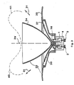
- Figure 3 shows a second embodiment of a loudspeaker according to the invention which incorporates rotational symmetry. This embodiment results from a 360° rotation of the structure of the horn-equipped loudspeaker shown in Figure 2 around an axis or symmetry 39.
- the electro-acoustic transducer contains a moving coil 1 which activates a diaphragm 30 held in place by flexible suspensions, such as 37 and 38.
- the diaphragm is a component of the input area of hollow horn 32 having conically-shaped walls such as 34 and 35. Operation is identical to that of the loud-speaker shown in Figure 2 and produces acoustical energy emitted mainly in the directions shown in Figure 3 along the axis of symmetry 39.
- the energy-emitting surface also produces two lobes 40 and 41.
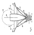
- Figure 4 shows a variant of the embodiment of the loudspeaker shown in Figure 3.
- an energy-emitting surface having one lobe 50 is provided which insures excellent directivity in the direction of the axis of symmetry 39. This result is achieved by a reduction in the angle formed by the conical diaphragm 30 and its axis of symmetry.
Landscapes
- Physics & Mathematics (AREA)
- Engineering & Computer Science (AREA)
- Acoustics & Sound (AREA)
- Signal Processing (AREA)
- Health & Medical Sciences (AREA)
- Otolaryngology (AREA)
- Obtaining Desirable Characteristics In Audible-Bandwidth Transducers (AREA)
- Diaphragms For Electromechanical Transducers (AREA)
- Audible-Bandwidth Dynamoelectric Transducers Other Than Pickups (AREA)
Applications Claiming Priority (2)
| Application Number | Priority Date | Filing Date | Title |
|---|---|---|---|
| US22517188A | 1988-07-28 | 1988-07-28 | |
| US225171 | 1994-04-08 |
Publications (2)
| Publication Number | Publication Date |
|---|---|
| EP0353092A2 true EP0353092A2 (fr) | 1990-01-31 |
| EP0353092A3 EP0353092A3 (fr) | 1991-01-02 |
Family
ID=22843828
Family Applications (1)
| Application Number | Title | Priority Date | Filing Date |
|---|---|---|---|
| EP19890307705 Withdrawn EP0353092A3 (fr) | 1988-07-28 | 1989-07-28 | Appareil et méthode de reproduction de sons haute fidélité |
Country Status (3)
| Country | Link |
|---|---|
| EP (1) | EP0353092A3 (fr) |
| JP (1) | JPH02161895A (fr) |
| KR (1) | KR910004063A (fr) |
Cited By (5)
| Publication number | Priority date | Publication date | Assignee | Title |
|---|---|---|---|---|
| EP0451885A1 (fr) * | 1990-03-13 | 1991-10-16 | Koninklijke Philips Electronics N.V. | Appareil audio ou vidéo à haut-parleur encastré |
| WO1996020576A1 (fr) * | 1994-12-23 | 1996-07-04 | Philips Electronics N.V. | Dispositif de reproduction sonore comprenant un pavillon acoustique et pavillon acoustique destine a ce dispositif |
| WO2000028780A1 (fr) * | 1998-11-06 | 2000-05-18 | New Transducers Limited | Haut-parleurs comprenant une source sonore de diffusion a phase non correlee |
| US7010138B1 (en) | 1996-09-03 | 2006-03-07 | New Transducers Limited | Loudspeakers |
| GB2442260A (en) * | 2006-09-29 | 2008-04-02 | Martin Audio Ltd | Loudspeaker diaphragm conforms to surrounding acoustic surface |
Families Citing this family (4)
| Publication number | Priority date | Publication date | Assignee | Title |
|---|---|---|---|---|
| WO2006093876A2 (fr) | 2005-03-01 | 2006-09-08 | Todd Henry | Transducteur audio a membrane a levier electromagnetique |
| JP5676580B2 (ja) * | 2010-11-10 | 2015-02-25 | パナソニックIpマネジメント株式会社 | スピーカ、及びそのスピーカを備える音響機器 |
| JP5804433B2 (ja) * | 2014-03-28 | 2015-11-04 | 裕昭 谷本 | スピーカ装置およびスピーカ装置の組立セット |
| JP7415129B2 (ja) * | 2019-10-04 | 2024-01-17 | オンキヨー株式会社 | スピーカー取付部材、および、これを備えるスピーカー、電子楽器 |
Family Cites Families (5)
| Publication number | Priority date | Publication date | Assignee | Title |
|---|---|---|---|---|
| US1887629A (en) * | 1928-07-23 | 1932-11-15 | Columbia Phonograph Co Inc | Sound reproducing apparatus |
| US2440078A (en) * | 1943-03-17 | 1948-04-20 | Gen Electric | Radio cabinet and speaker mounting |
| US2956636A (en) * | 1956-06-11 | 1960-10-18 | Sipko L Boersma | Loudspeaker |
| GB1224475A (en) * | 1968-01-13 | 1971-03-10 | Mario Cesati | Compression chamber loudspeakers |
| US4297538A (en) * | 1979-07-23 | 1981-10-27 | The Stoneleigh Trust | Resonant electroacoustic transducer with increased band width response |
-
1989
- 1989-07-27 KR KR1019890010607A patent/KR910004063A/ko not_active Ceased
- 1989-07-28 JP JP1196439A patent/JPH02161895A/ja active Pending
- 1989-07-28 EP EP19890307705 patent/EP0353092A3/fr not_active Withdrawn
Cited By (6)
| Publication number | Priority date | Publication date | Assignee | Title |
|---|---|---|---|---|
| EP0451885A1 (fr) * | 1990-03-13 | 1991-10-16 | Koninklijke Philips Electronics N.V. | Appareil audio ou vidéo à haut-parleur encastré |
| WO1996020576A1 (fr) * | 1994-12-23 | 1996-07-04 | Philips Electronics N.V. | Dispositif de reproduction sonore comprenant un pavillon acoustique et pavillon acoustique destine a ce dispositif |
| US7010138B1 (en) | 1996-09-03 | 2006-03-07 | New Transducers Limited | Loudspeakers |
| WO2000028780A1 (fr) * | 1998-11-06 | 2000-05-18 | New Transducers Limited | Haut-parleurs comprenant une source sonore de diffusion a phase non correlee |
| AU746872B2 (en) * | 1998-11-06 | 2002-05-02 | New Transducers Limited | Loudspeakers comprising a phase uncorrelated diffuse sound source |
| GB2442260A (en) * | 2006-09-29 | 2008-04-02 | Martin Audio Ltd | Loudspeaker diaphragm conforms to surrounding acoustic surface |
Also Published As
| Publication number | Publication date |
|---|---|
| KR910004063A (ko) | 1991-02-28 |
| EP0353092A3 (fr) | 1991-01-02 |
| JPH02161895A (ja) | 1990-06-21 |
Similar Documents
| Publication | Publication Date | Title |
|---|---|---|
| US5103482A (en) | Apparatus and method for reproducing high fidelity sound | |
| US4965839A (en) | Electro acoustic transducer and loudspeaker | |
| US5025885A (en) | Multiple chamber loudspeaker system | |
| US4516428A (en) | Acceleration vibration detector | |
| US5815589A (en) | Push-pull transmission line loudspeaker | |
| CA1219056A (fr) | Transducteur electroacoustique integre | |
| JP2510714B2 (ja) | 周波数補償型補聴器用マイクロホン組立体 | |
| US4419545A (en) | Electret transducer | |
| US4528426A (en) | Directional microphone assembly | |
| US4295006A (en) | Speaker system | |
| EP0353092A2 (fr) | Appareil et méthode de reproduction de sons haute fidélité | |
| US4727583A (en) | Telephone transducer with improved frequency response | |
| US3053339A (en) | Pipe microphone | |
| EP0475208B1 (fr) | Transducteur piézoélectrique électroacoustique | |
| WO1995023434A1 (fr) | Transducteur piezoelectrique, emettant un son | |
| JPS5979700A (ja) | 振動検知装置 | |
| KR102020233B1 (ko) | 다중 드라이버 이어폰 | |
| US20020012439A1 (en) | Diaphragm-type bass loudspeaker | |
| US1788103A (en) | Loud-speaker | |
| JPH09215089A (ja) | 音響波放射装置 | |
| KR102724505B1 (ko) | 다중회로 불연 피에조 압전 스피커 장치 | |
| GB2118398A (en) | Moving coil electroacoustic transducers | |
| US4860365A (en) | Method of fractionating the sound restoration of modulated signals in parallel mounted transducers, and sets of corresponding transducers | |
| JP2660306B2 (ja) | 多重チャンバ型ラウドスピーカ・システム | |
| CN1101202A (zh) | 不对称电声换能 |
Legal Events
| Date | Code | Title | Description |
|---|---|---|---|
| PUAI | Public reference made under article 153(3) epc to a published international application that has entered the european phase |
Free format text: ORIGINAL CODE: 0009012 |
|
| AK | Designated contracting states |
Kind code of ref document: A2 Designated state(s): DE GB IT NL |
|
| PUAL | Search report despatched |
Free format text: ORIGINAL CODE: 0009013 |
|
| AK | Designated contracting states |
Kind code of ref document: A3 Designated state(s): DE GB IT NL |
|
| 17P | Request for examination filed |
Effective date: 19910608 |
|
| STAA | Information on the status of an ep patent application or granted ep patent |
Free format text: STATUS: THE APPLICATION IS DEEMED TO BE WITHDRAWN |
|
| 18D | Application deemed to be withdrawn |
Effective date: 19930202 |