EP0353205A1 - Ensemble de distribution de carburant apte à se déplacer de haut en bas, prévu pour être utilisé sur des véhicules de ravitaillement pour avions - Google Patents
Ensemble de distribution de carburant apte à se déplacer de haut en bas, prévu pour être utilisé sur des véhicules de ravitaillement pour avions Download PDFInfo
- Publication number
- EP0353205A1 EP0353205A1 EP89830327A EP89830327A EP0353205A1 EP 0353205 A1 EP0353205 A1 EP 0353205A1 EP 89830327 A EP89830327 A EP 89830327A EP 89830327 A EP89830327 A EP 89830327A EP 0353205 A1 EP0353205 A1 EP 0353205A1
- Authority
- EP
- European Patent Office
- Prior art keywords
- station
- refuelling
- airplane
- lowered
- rails
- Prior art date
- Legal status (The legal status is an assumption and is not a legal conclusion. Google has not performed a legal analysis and makes no representation as to the accuracy of the status listed.)
- Granted
Links
- 239000000446 fuel Substances 0.000 title claims abstract description 15
- 238000012384 transportation and delivery Methods 0.000 title abstract description 28
- 230000008093 supporting effect Effects 0.000 claims abstract description 9
- 241000168041 Mazama Species 0.000 claims description 2
- 239000007787 solid Substances 0.000 abstract description 2
- 238000010276 construction Methods 0.000 abstract 1
- 239000003981 vehicle Substances 0.000 description 14
- 239000002828 fuel tank Substances 0.000 description 9
- 230000008439 repair process Effects 0.000 description 7
- 238000012423 maintenance Methods 0.000 description 6
- 238000001914 filtration Methods 0.000 description 3
- 238000007789 sealing Methods 0.000 description 3
- 238000004804 winding Methods 0.000 description 3
- 230000001681 protective effect Effects 0.000 description 2
- 208000034423 Delivery Diseases 0.000 description 1
- 238000007599 discharging Methods 0.000 description 1
- 238000006073 displacement reaction Methods 0.000 description 1
- 238000009434 installation Methods 0.000 description 1
Images

Classifications
-
- B—PERFORMING OPERATIONS; TRANSPORTING
- B67—OPENING, CLOSING OR CLEANING BOTTLES, JARS OR SIMILAR CONTAINERS; LIQUID HANDLING
- B67D—DISPENSING, DELIVERING OR TRANSFERRING LIQUIDS, NOT OTHERWISE PROVIDED FOR
- B67D7/00—Apparatus or devices for transferring liquids from bulk storage containers or reservoirs into vehicles or into portable containers, e.g. for retail sale purposes
- B67D7/04—Apparatus or devices for transferring liquids from bulk storage containers or reservoirs into vehicles or into portable containers, e.g. for retail sale purposes for transferring fuels, lubricants or mixed fuels and lubricants
-
- B—PERFORMING OPERATIONS; TRANSPORTING
- B64—AIRCRAFT; AVIATION; COSMONAUTICS
- B64F—GROUND OR AIRCRAFT-CARRIER-DECK INSTALLATIONS SPECIALLY ADAPTED FOR USE IN CONNECTION WITH AIRCRAFT; DESIGNING, MANUFACTURING, ASSEMBLING, CLEANING, MAINTAINING OR REPAIRING AIRCRAFT, NOT OTHERWISE PROVIDED FOR; HANDLING, TRANSPORTING, TESTING OR INSPECTING AIRCRAFT COMPONENTS, NOT OTHERWISE PROVIDED FOR
- B64F1/00—Ground or aircraft-carrier-deck installations
- B64F1/28—Liquid-handling installations specially adapted for fuelling stationary aircraft
-
- Y—GENERAL TAGGING OF NEW TECHNOLOGICAL DEVELOPMENTS; GENERAL TAGGING OF CROSS-SECTIONAL TECHNOLOGIES SPANNING OVER SEVERAL SECTIONS OF THE IPC; TECHNICAL SUBJECTS COVERED BY FORMER USPC CROSS-REFERENCE ART COLLECTIONS [XRACs] AND DIGESTS
- Y10—TECHNICAL SUBJECTS COVERED BY FORMER USPC
- Y10T—TECHNICAL SUBJECTS COVERED BY FORMER US CLASSIFICATION
- Y10T137/00—Fluid handling
- Y10T137/6851—With casing, support, protector or static constructional installations
- Y10T137/6855—Vehicle
- Y10T137/6899—With hose reel storage means
-
- Y—GENERAL TAGGING OF NEW TECHNOLOGICAL DEVELOPMENTS; GENERAL TAGGING OF CROSS-SECTIONAL TECHNOLOGIES SPANNING OVER SEVERAL SECTIONS OF THE IPC; TECHNICAL SUBJECTS COVERED BY FORMER USPC CROSS-REFERENCE ART COLLECTIONS [XRACs] AND DIGESTS
- Y10—TECHNICAL SUBJECTS COVERED BY FORMER USPC
- Y10T—TECHNICAL SUBJECTS COVERED BY FORMER US CLASSIFICATION
- Y10T137/00—Fluid handling
- Y10T137/6851—With casing, support, protector or static constructional installations
- Y10T137/6855—Vehicle
- Y10T137/691—With retractable or nonuse-positionable support wheel
Definitions
- This invention refers to a fuel delivery system for refuelling airplanes comprising a delivery station mounted on an airplane refuelling tank-vehicle and movable from a rest position wherein it is completely received within a suitable, practically inaccessible, housing formed on the tank to an operative position wherein it is completely outside the housing and perfectly accessible to the operator who is carrying out the refuelling, operation; the supporting frame of the system, which is of simple and solid contruction, is controlled to move from the one position to the other preferably through hydraulic mechanical means.
- the delivery system of the invention substantially comprises a frame provided with rails for supporting the delivery station which comprises the traditional fuel delivery and control means such as hoses and winding reels, meters, filtering and safety devices and the like.
- the frame can be drawn out of its protective housing, which housing is preferably placed on the back of the vehicle, sliding on downwardly inclined guides to a lowered position outside the vehicle, by means of a preferably oleodynamic mechanical control.
- the fuel trucks used at present to movably carry out the refuelling of airplanes usually comprises a fuel tank containing the fuel to be delivered as well as the indispensable delivery system or station; the latter comprising all the members, instruments and devices necessary to carry out this operation that requires particular and continuous attention and controls.
- the fuel trucks used at present for refuelling airplanes force the operator to work in bad conditions and the delivery hoses to follow non rectilinear and accordingly longer paths when the movable refuelling station is connected to the airplane to be refuelled.
- this invention is intended to overcome the above-mentioned drawbacks providing a refuelling system or station movable between a raised, rest position and a lowered, operative position, wherein the movement to the lowered, operative position of the system also causes the system to get out of the receiving and protecting housing.
- the operator can simultaneously see the control panel and all the other members of the refuelling station still having a direct view of the airplane, even if the latter is parked at either the right or left side of the airplane refuelling vehicle, or behind the operator's shoulders; furthermore, the lowering and coming out displacement of the refuelling station facilitate the controls and maintenance of the members and accessories thereof as well as any possible integral replacement thereof in case of a serious failure of the system.
- the rotational axis of the delivery hose winding reel is not horizontal, accordingly the hose path is rectilinear when the refuelling station is connected to ariplanes parked either at the right or at the left side or at the back side with respect to the refuelling vehicle.
- the elliptical back closing door is important since it protects the members and accessories of the refuelling station when it is closed and the vehicle is moving and parking and becomes a protective roof for the station and the operator during refuelling as well as a support of the light systems lighting the refuelling station during operations at night.
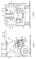
- a "fuel truck” is shown therein, that is a fuel tank intended to refuel airplanes, comprising the system or station according to the invention.
- the fuel truck of the invention substantially comprises a chassis TT; a driver's cab CG and a tank SS containing the fuel.
- chassis TT extends back-wardly beyond the rear end EP of tank SS which in turn extends upwardly and sidewardly to form a rearward and downward open “chamber” or room, as shown by reference number 10.
- the rear opening of chamber 11 is closed by a door 12 having a substantially oval shape.
- Door 12 is moved by a jack 13 from a "station at rest” lowered, closed position ( Figure 1) to a "station in use” raised open position ( Figure 2).
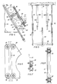
- a square frame 14 is placed within chamber 11 and two sloping rails 15 are secured thereto ( Figure 5).
- the refuelling system or station as it is shown, is slidably mounted on rails 15 thus moving from a raised position wherein it is completely received within chamber 11 to a lowered position wherein it partially protrudes therefrom.
- a top joist 16 and a bottom joist 18 are mounted on rails 15 which joists support both telescopic pipes 19A, 19B feeding and delivering.
- the fuel of tank SS and the oleodynamic unit or hydraulic jack 20 controlling the system movements (Figure 5).
- the refuelling station referred to as a whole by reference number 30 is a unit comprising supporting elements, such as bearing brockets or slide 31 each provided with four wheels 32, and operative supporting members such as the big cylindrical body of filter 33, the "aquastop" device 34, the big single coil reel 35 and the like.
- single coil reel 35 is inclined and this facilitates winding and unwinding of hose 41.
- Station 30 also comprises the reel moving motor 36, a meter 37, a control panel 38 also comprising the "dead-man" delivery control, that, as it is known, immediately interrupts the delivery if the operator takes his hand off, and a fire estinguisher 40.
- the two telescopic pipes which easily follow the movements of station 30 are used the one to deliver the fuel to the airplane tank and the other to carry out the opposite operation, that is discharging the fuel therefrom as it is sometimes necessary.
- the invention provides a refuelling system or station which completely overcomes the drawbacks of the traditional solutions, since the some can be lowered to the level of the operator in a comfortable and accessible position.
- control levers and knobs for lifting door 12 and raising and lowering the whole system are also at the level of the operator.
- Door 12 will also be provided with a light source, referred to by reference number 39, to facilitate the operations at night.
- a particular feature of the station according to the invention is the shape of rails 15 having a square section and of wheels 32 having a V-shaped groove so that the matching of pairs of wheels allows the best engagement to be obtained between the wheels and the respective rail without relative slacks and movements, as it is shown in Figures 6, 7 and 8.
Landscapes
- Engineering & Computer Science (AREA)
- Mechanical Engineering (AREA)
- Aviation & Aerospace Engineering (AREA)
- Loading And Unloading Of Fuel Tanks Or Ships (AREA)
- Cooling, Air Intake And Gas Exhaust, And Fuel Tank Arrangements In Propulsion Units (AREA)
- Body Structure For Vehicles (AREA)
- Fire-Extinguishing By Fire Departments, And Fire-Extinguishing Equipment And Control Thereof (AREA)
Priority Applications (1)
| Application Number | Priority Date | Filing Date | Title |
|---|---|---|---|
| AT89830327T ATE82226T1 (de) | 1988-07-28 | 1989-07-14 | Auf- und abbewegbare kraftstoffabgabevorrichtung, vorgesehen fuer tankwagen zum betanken von flugzeugen. |
Applications Claiming Priority (2)
| Application Number | Priority Date | Filing Date | Title |
|---|---|---|---|
| IT4824688 | 1988-07-28 | ||
| IT8848246A IT1224699B (it) | 1988-07-28 | 1988-07-28 | Gruppo erogatore estraibile ed abbassabile per i veicoli destinati a rifornire carburante agli aeromobili |
Publications (2)
| Publication Number | Publication Date |
|---|---|
| EP0353205A1 true EP0353205A1 (fr) | 1990-01-31 |
| EP0353205B1 EP0353205B1 (fr) | 1992-11-11 |
Family
ID=11265465
Family Applications (1)
| Application Number | Title | Priority Date | Filing Date |
|---|---|---|---|
| EP89830327A Expired - Lifetime EP0353205B1 (fr) | 1988-07-28 | 1989-07-14 | Ensemble de distribution de carburant apte à se déplacer de haut en bas, prévu pour être utilisé sur des véhicules de ravitaillement pour avions |
Country Status (6)
| Country | Link |
|---|---|
| US (1) | US4981272A (fr) |
| EP (1) | EP0353205B1 (fr) |
| JP (1) | JPH02155900A (fr) |
| AT (1) | ATE82226T1 (fr) |
| DE (1) | DE68903443T2 (fr) |
| IT (1) | IT1224699B (fr) |
Families Citing this family (15)
| Publication number | Priority date | Publication date | Assignee | Title |
|---|---|---|---|---|
| US5575441A (en) * | 1994-11-28 | 1996-11-19 | The United States Of America As Represented By The Secretary Of The Air Force | Fuel liquid/vapor vent containment/recovery system |
| USD385891S (en) * | 1995-05-16 | 1997-11-04 | Spatco | Petroleum delivery truck fuel delivery system |
| US5893398A (en) * | 1997-06-27 | 1999-04-13 | Garrett, Jr.; Detrolia | Aircraft servicing system and method |
| US5915654A (en) * | 1997-09-29 | 1999-06-29 | Kofflin; David Francis | Pre-conditioned air connection ring |
| US6065511A (en) * | 1998-09-11 | 2000-05-23 | Mcclintock; Gene | Vehicle fueling system |
| US6598830B1 (en) | 2002-06-12 | 2003-07-29 | Sikorsky Aircraft Corporation | Telescoping refueling probe |
| DE102005046312B4 (de) | 2005-09-27 | 2010-07-08 | Meyerinck, Wolfgang von, Dipl.-Ing. | Selbstfahrendes Tankfahrzeug zur Betankung von Flugzeugen |
| EP2122325B1 (fr) * | 2007-01-16 | 2013-03-27 | Fuel Guard Systems Corporation | Procédé et système automatique de commande de distributeur et de détection de qualité de carburant, en particulier pour des applications d'avitaillement d'aéronefs |
| US8740251B2 (en) * | 2009-09-02 | 2014-06-03 | Spokane Industries, Inc. | Ground support service cart apparatus and methods |
| US8777125B2 (en) | 2011-04-29 | 2014-07-15 | Cnh Industrial America Llc | Deployable operator interface for an agricultural vehicle |
| US9530290B2 (en) | 2013-01-18 | 2016-12-27 | Fuel Guard Systems Corporation | Apparatuses and methods for providing visual indication of dynamic process fuel quality delivery conditions with use of multiple colored indicator lights |
| EP3594128B1 (fr) | 2015-01-29 | 2021-06-30 | Ray Hutchinson | Eau automatisée et détection de particules pour la distribution de carburant comprenant un carburant d'aviation et appareils, systèmes et procédés associés |
| CN105271098A (zh) * | 2015-10-23 | 2016-01-27 | 重庆市合川区环宇配件厂 | 汽配加油总成 |
| CN105293416A (zh) * | 2015-10-23 | 2016-02-03 | 重庆市合川区环宇配件厂 | 便移动型加油器 |
| CN105293414A (zh) * | 2015-10-23 | 2016-02-03 | 重庆市合川区环宇配件厂 | 燃油注输设备 |
Citations (4)
| Publication number | Priority date | Publication date | Assignee | Title |
|---|---|---|---|---|
| US2603384A (en) * | 1952-07-15 | Sheetsxsheet i | ||
| FR2034100A7 (fr) * | 1969-02-03 | 1970-12-11 | Coder Materiel | |
| FR2095295A3 (fr) * | 1970-06-16 | 1972-02-11 | Gloster Saro Ltd | |
| FR2470087A1 (fr) * | 1979-11-20 | 1981-05-29 | Ivan Sarl | Ensemble orientable de distribution-comptage pour liquides, gaz et pulverulents |
Family Cites Families (5)
| Publication number | Priority date | Publication date | Assignee | Title |
|---|---|---|---|---|
| US2735717A (en) * | 1956-02-21 | harman | ||
| US297A (en) * | 1837-07-29 | Improvement in fire-arms | ||
| IT1101971B (it) * | 1978-02-23 | 1985-10-07 | Cutore Gaetano | Complesso perfezionato a scomparsa totale per il rifornimento di carburante ad aeromobili |
| US4534384A (en) * | 1982-12-15 | 1985-08-13 | Flight Refueling, Inc. | Reel system for axially extending hose |
| US4540144A (en) * | 1984-01-05 | 1985-09-10 | United Technologies Corporation | Telescoping fuel probe |
-
1988
- 1988-07-28 IT IT8848246A patent/IT1224699B/it active
-
1989
- 1989-07-14 AT AT89830327T patent/ATE82226T1/de not_active IP Right Cessation
- 1989-07-14 DE DE8989830327T patent/DE68903443T2/de not_active Expired - Fee Related
- 1989-07-14 EP EP89830327A patent/EP0353205B1/fr not_active Expired - Lifetime
- 1989-07-25 US US07/385,217 patent/US4981272A/en not_active Expired - Fee Related
- 1989-07-27 JP JP1196471A patent/JPH02155900A/ja active Pending
Patent Citations (4)
| Publication number | Priority date | Publication date | Assignee | Title |
|---|---|---|---|---|
| US2603384A (en) * | 1952-07-15 | Sheetsxsheet i | ||
| FR2034100A7 (fr) * | 1969-02-03 | 1970-12-11 | Coder Materiel | |
| FR2095295A3 (fr) * | 1970-06-16 | 1972-02-11 | Gloster Saro Ltd | |
| FR2470087A1 (fr) * | 1979-11-20 | 1981-05-29 | Ivan Sarl | Ensemble orientable de distribution-comptage pour liquides, gaz et pulverulents |
Also Published As
| Publication number | Publication date |
|---|---|
| ATE82226T1 (de) | 1992-11-15 |
| IT8848246A0 (it) | 1988-07-28 |
| IT1224699B (it) | 1990-10-18 |
| DE68903443D1 (de) | 1992-12-17 |
| JPH02155900A (ja) | 1990-06-14 |
| DE68903443T2 (de) | 1993-06-03 |
| US4981272A (en) | 1991-01-01 |
| EP0353205B1 (fr) | 1992-11-11 |
Similar Documents
| Publication | Publication Date | Title |
|---|---|---|
| EP0353205A1 (fr) | Ensemble de distribution de carburant apte à se déplacer de haut en bas, prévu pour être utilisé sur des véhicules de ravitaillement pour avions | |
| US3706144A (en) | Control means for a snow plow | |
| US4312418A (en) | Pivoted valve and hood for lift truck | |
| US7789412B2 (en) | Adjusting device, air deflecting system, control member and device enabling aerodynamic resistance of a semi-trailer to be reduced | |
| US7850206B2 (en) | Automatic flap lifter and method | |
| US6595330B1 (en) | Work platform control system for a boom-type vehicle | |
| WO2017173379A1 (fr) | Système de traitement de fluide de véhicule | |
| US5305805A (en) | Fixed hydrant cart with non-articulating coupling | |
| GB2158784A (en) | Improvements in service vehicles | |
| EP3211141A2 (fr) | Camion-benne avec châssis articulé et poste de conduite réversible | |
| US5848870A (en) | Single person catering vehicle | |
| US6623038B2 (en) | Automatic lifting mud flap assembly | |
| KR20200092427A (ko) | 작업 차량 | |
| US5915500A (en) | Lift apparatus with tire adapter | |
| GB2152899A (en) | A device for multi-directional tipping of a skip or container carried by a vehicle | |
| US5678616A (en) | Fixed installation for filling aircraft with fuel | |
| WO1996024503A1 (fr) | Systeme de chauffage/conditionnement de l'air | |
| US5163473A (en) | Valve system for automatic fuel delivery | |
| CA1265477A (fr) | Vehicule de manutention | |
| US6240803B1 (en) | Gear change mechanism in a vehicle | |
| CA3203847A1 (fr) | Ambulance | |
| CN109292687A (zh) | 一种用于叉车上安装液压先导手柄的翻转机构 | |
| DE102005046312B4 (de) | Selbstfahrendes Tankfahrzeug zur Betankung von Flugzeugen | |
| JPH0781548A (ja) | 燃料給油車のインターロック装置 | |
| WO1994014652A1 (fr) | Vehicule-citerne d'aeroport |
Legal Events
| Date | Code | Title | Description |
|---|---|---|---|
| PUAI | Public reference made under article 153(3) epc to a published international application that has entered the european phase |
Free format text: ORIGINAL CODE: 0009012 |
|
| AK | Designated contracting states |
Kind code of ref document: A1 Designated state(s): AT BE CH DE ES FR GB GR LI LU NL SE |
|
| 17P | Request for examination filed |
Effective date: 19900214 |
|
| 17Q | First examination report despatched |
Effective date: 19910814 |
|
| GRAA | (expected) grant |
Free format text: ORIGINAL CODE: 0009210 |
|
| AK | Designated contracting states |
Kind code of ref document: B1 Designated state(s): AT BE CH DE ES FR GB GR LI LU NL SE |
|
| PG25 | Lapsed in a contracting state [announced via postgrant information from national office to epo] |
Ref country code: SE Effective date: 19921111 Ref country code: NL Effective date: 19921111 Ref country code: LI Effective date: 19921111 Ref country code: GR Free format text: LAPSE BECAUSE OF FAILURE TO SUBMIT A TRANSLATION OF THE DESCRIPTION OR TO PAY THE FEE WITHIN THE PRESCRIBED TIME-LIMIT Effective date: 19921111 Ref country code: ES Free format text: THE PATENT HAS BEEN ANNULLED BY A DECISION OF A NATIONAL AUTHORITY Effective date: 19921111 Ref country code: CH Effective date: 19921111 Ref country code: BE Effective date: 19921111 Ref country code: AT Effective date: 19921111 |
|
| REF | Corresponds to: |
Ref document number: 82226 Country of ref document: AT Date of ref document: 19921115 Kind code of ref document: T |
|
| REF | Corresponds to: |
Ref document number: 68903443 Country of ref document: DE Date of ref document: 19921217 |
|
| ET | Fr: translation filed | ||
| REG | Reference to a national code |
Ref country code: CH Ref legal event code: PL |
|
| PGFP | Annual fee paid to national office [announced via postgrant information from national office to epo] |
Ref country code: FR Payment date: 19930330 Year of fee payment: 5 |
|
| NLV1 | Nl: lapsed or annulled due to failure to fulfill the requirements of art. 29p and 29m of the patents act | ||
| PG25 | Lapsed in a contracting state [announced via postgrant information from national office to epo] |
Ref country code: LU Free format text: LAPSE BECAUSE OF NON-PAYMENT OF DUE FEES Effective date: 19930731 |
|
| PLBE | No opposition filed within time limit |
Free format text: ORIGINAL CODE: 0009261 |
|
| STAA | Information on the status of an ep patent application or granted ep patent |
Free format text: STATUS: NO OPPOSITION FILED WITHIN TIME LIMIT |
|
| PGFP | Annual fee paid to national office [announced via postgrant information from national office to epo] |
Ref country code: DE Payment date: 19930930 Year of fee payment: 5 |
|
| 26N | No opposition filed | ||
| PGFP | Annual fee paid to national office [announced via postgrant information from national office to epo] |
Ref country code: GB Payment date: 19931217 Year of fee payment: 5 |
|
| PG25 | Lapsed in a contracting state [announced via postgrant information from national office to epo] |
Ref country code: GB Effective date: 19940714 |
|
| GBPC | Gb: european patent ceased through non-payment of renewal fee |
Effective date: 19940714 |
|
| PG25 | Lapsed in a contracting state [announced via postgrant information from national office to epo] |
Ref country code: FR Effective date: 19950331 |
|
| PG25 | Lapsed in a contracting state [announced via postgrant information from national office to epo] |
Ref country code: DE Effective date: 19950401 |
|
| REG | Reference to a national code |
Ref country code: FR Ref legal event code: ST |