EP0353309A1 - Verfahren zum bau eines lochs - Google Patents
Verfahren zum bau eines lochs Download PDFInfo
- Publication number
- EP0353309A1 EP0353309A1 EP89901623A EP89901623A EP0353309A1 EP 0353309 A1 EP0353309 A1 EP 0353309A1 EP 89901623 A EP89901623 A EP 89901623A EP 89901623 A EP89901623 A EP 89901623A EP 0353309 A1 EP0353309 A1 EP 0353309A1
- Authority
- EP
- European Patent Office
- Prior art keywords
- diameter
- drilling
- tour
- profile
- tube
- Prior art date
- Legal status (The legal status is an assumption and is not a legal conclusion. Google has not performed a legal analysis and makes no representation as to the accuracy of the status listed.)
- Granted
Links
Images
Classifications
-
- E—FIXED CONSTRUCTIONS
- E21—EARTH OR ROCK DRILLING; MINING
- E21B—EARTH OR ROCK DRILLING; OBTAINING OIL, GAS, WATER, SOLUBLE OR MELTABLE MATERIALS OR A SLURRY OF MINERALS FROM WELLS
- E21B43/00—Methods or apparatus for obtaining oil, gas, water, soluble or meltable materials or a slurry of minerals from wells
- E21B43/02—Subsoil filtering
- E21B43/10—Setting of casings, screens, liners or the like in wells
- E21B43/103—Setting of casings, screens, liners or the like in wells of expandable casings, screens, liners, or the like
-
- E—FIXED CONSTRUCTIONS
- E21—EARTH OR ROCK DRILLING; MINING
- E21B—EARTH OR ROCK DRILLING; OBTAINING OIL, GAS, WATER, SOLUBLE OR MELTABLE MATERIALS OR A SLURRY OF MINERALS FROM WELLS
- E21B17/00—Drilling rods or pipes; Flexible drill strings; Kellies; Drill collars; Sucker rods; Cables; Casings; Tubings
-
- E—FIXED CONSTRUCTIONS
- E21—EARTH OR ROCK DRILLING; MINING
- E21B—EARTH OR ROCK DRILLING; OBTAINING OIL, GAS, WATER, SOLUBLE OR MELTABLE MATERIALS OR A SLURRY OF MINERALS FROM WELLS
- E21B29/00—Cutting or destroying pipes, packers, plugs or wire lines, located in boreholes or wells, e.g. cutting of damaged pipes, of windows; Deforming of pipes in boreholes or wells; Reconditioning of well casings while in the ground
- E21B29/10—Reconditioning of well casings, e.g. straightening
-
- E—FIXED CONSTRUCTIONS
- E21—EARTH OR ROCK DRILLING; MINING
- E21B—EARTH OR ROCK DRILLING; OBTAINING OIL, GAS, WATER, SOLUBLE OR MELTABLE MATERIALS OR A SLURRY OF MINERALS FROM WELLS
- E21B33/00—Sealing or packing boreholes or wells
- E21B33/10—Sealing or packing boreholes or wells in the borehole
- E21B33/13—Methods or devices for cementing, for plugging holes, crevices or the like
- E21B33/14—Methods or devices for cementing, for plugging holes, crevices or the like for cementing casings into boreholes
-
- E—FIXED CONSTRUCTIONS
- E21—EARTH OR ROCK DRILLING; MINING
- E21B—EARTH OR ROCK DRILLING; OBTAINING OIL, GAS, WATER, SOLUBLE OR MELTABLE MATERIALS OR A SLURRY OF MINERALS FROM WELLS
- E21B7/00—Special methods or apparatus for drilling
Definitions
- the invention relates to drilling methods and, in particular, relates to a method for constructing a multi-tube tour drilling under complicated conditions of drilling rocks.
- the present invention can be most effectively used to cover layers inconsistent with drilling conditions, i. H. of layers with abnormal deposit pressures of the zones of rock or rock fall in the borehole as well as the complication zones, which are characterized by an intensive flushing loss, liquid or gas inflow from the digested layer and cannot be sealed with the available means.
- a method of constructing a multi-pipe tour well which includes drilling rock, which is accompanied by winding the bottom of the borehole to wash away the rock crushed by drilling.
- the reservoir pressures are balanced by the pressure of the flushing column, which is regulated by changing the specific weight of the flushing.
- the layers often differ greatly due to the pressure within the deposit, which makes it impossible to regulate this balance by changing the specific weight of the mud.
- the digested layer is covered with a casing pipe tour before the subsequent layer is digested, which is then cemented in order to prevent the disrupted layers from influencing one another; after choosing a specific flushing weight corresponding to the reservoir pressure of the subsequent layer, the drilling continues, but already with a chisel of smaller diameter.
- the borehole is formed from the borehole mouth to the productive layer with a gradually decreasing diameter, whereby several concentrically arranged casing pipes are used to solidify the borehole walls used tours.
- These pipe tours are usually referred to as guide pipe tours, conductors, intermediate pipe tours and conveyor pipe tours according to their functional intended use.
- Such a method for the construction of boreholes requires a great deal of time, cement and casing pipes.
- a method of building multi-tube tour bores is also known (SU, A, 907220), which involves drilling rocks and consolidating them with casing pipes which form a guide tube tour, a conductor, intermediate pipe tours and a production tube tour.
- SU multi-tube tour bores
- casing pipes which form a guide tube tour, a conductor, intermediate pipe tours and a production tube tour.
- profiled tubes which are expanded when they are installed by generating a pressure gradient in them and then rolling them on. This makes it possible to cover the zone of flushing loss and continue drilling the hole in order to then install a corresponding casing tour.
- the construction of the bore represents a multi-pipe tour drilling with a concentric arrangement of the casing tours, ie the use of intermediate pipe tours is not excluded, which are intended to cover layers incompatible with the drilling conditions. Consequently, the expenditure of time and materials for the construction of a borehole is also high in this case, which is also formed with a borehole diameter that gradually decreases depending on the deep drilling.
- it is often necessary to replace drilling tools for the corresponding borehole diameter which also lengthens and increases the cost of the process, the ind strie is forced to manufacture many types of drilling tools and equipment for no reason.
- the present invention has for its object to develop in such a method for the construction of a multi-tube tour, which ensures the consolidation of the bore after the installation of guide tube tours and a conductor with casing tours, which have the same inner diameter.
- the object is achieved in that, in a method for the construction of a multi-pipe tour drilling, which involves drilling rocks, solidifying them with a guide pipe tour, a conductor, covering layers which are incompatible with the drilling conditions while sealing the complication zones with profile pipes, which are used during installation widened and rolled into the previously expanded complication zones, and includes the installation of a conveyor tube tour, according to the invention, once the bore has been solidified with the guide tube tour and the conductor, drilling with chisels of the same diameter is carried out, the sealing of the complication zones and the coverage of the with regard to the drilling conditions, incompatible layers are carried out with profiled tubes which, after their expansion, have the same inner diameter and which are successively depending on the digestion of those which are incompatible with the drilling conditions Layers built.
- At least one of the profile tubes has an initial outside diameter which is smaller than the borehole diameter in the complication zone, with the inside diameter being brought to the inside diameter of the other rolled tubes when the tube is expanded by rolling.
- the profiled tube prefferably be rolled up to a diameter which exceeds its initial diameter by 3 to 5%. This ensures a maximum hardness increase of the pipe metal depending on the type of metal and wall thickness by 130 to 260%. With a further increase in the diameter of the profile tube by more than 5%, its resistance to the crushing external pressure is only slightly increased, and this leads to a dangerous decrease in the jand thickness of the profile tube.
- a well with a chisel of large diameter is drilled and solidified with a guide casing tour. Then you continue drilling with a chisel of smaller diameter and solidify again with a casing tour, which is referred to as a conductor. Then drill to the projected depth with a chisel of the same diameter, with a reamer being placed above the chisel before digging up the incompatible layers, using the diameter of the hole drilled by the chisel to one Diameter is expanded, which is the outer diameter of the expanded profile tubes.
- a layer with a pressure that exceeds the crushing strength of the profiled tubes is opened up by drilling, then between these profiled tubes are placed, the outer diameter of which before the profiling thereof is smaller than the borehole diameter; the length of the profile tubes is slightly larger than the complication zone with abnormally high reservoir pressure, and they become rolled up to a diameter that exceeds the initial diameter of the pipes by 3 to 5% before they are profiled.
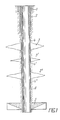
- drilling for a lead casing tour 1 (Fig. 1) was carried out to a depth of 6 m using a 394 mm diameter chisel and the drilling was carried out with conventional 324 mm casing pipes Solidified outer diameter.
- Drilling was then continued with a 295 mm diameter bit to a depth of 300 mm while drilling with a drilling fluid of 1.1 g / cm 3 density and the drilling was consolidated with a 245 mm diameter conductor 2. Then the drilling was carried out using a chisel with a diameter of 215.9 mm to the projected depth of the drilling of 1800 m.
- Zone 3 of the water outlet was sealed at a depth of 460 to 470 m with profiled tubes 4, which without reducing the borehole diameter in an interval of 380 to 480 m by dressing the same with a pressure of 10 to 12 MPa of the liquid acting from the inside and Subsequent pressing by rolling was installed on the wall bottom of the borehole, which had previously been expanded to a diameter of 235 mm using a scraper.
- Zones 3 1 of the oil outlet and the water outlet were sealed at a depth of 600 to 640 m using a similar procedure.
- the profile pipes 4 1 were installed in an interwall of 534 to 650 m.
- Zone 3 11 of the water outlet was also sealed at a depth of 820 to 840 m by means of profile pipes 4 11 in an interval of 800 to 900 m.
- drilling was continued using a 215.5 mm diameter chisel using a drilling fluid with a density that corresponds to the geological conditions of a productive layer 5 to be digested, namely with a density of 1.43 g / cm 3 . and and a conveyor tube tour 6 with a diameter of 146 mm was installed.
- M in the depths of 330-800 of a drilling fluid having a density of 1.29 g / cm 3 and at the depth of 800 m was up to 900 using - at a density of 1, 6 g / cm 3 drilled.
- the set of profile tubes 4 is installed on a drill pipe 11 up to the complication zone 7 with an abnormally high deposit pressure, so that this zone 7 is accommodated in relation to the central part 3 of the profile tube to be solidified, the diameter of the circumference thereof being 3 to 5% smaller than the borehole diameter in the previously enlarged zone 7, while the diameter of the lower and the upper part of the set of pipes 4 is equal to the diameter of the enlarged part of the hole in the complication zone 7.
- the middle tube 4 is expanded and pressed tightly against the borehole walls, while the packer elements 8 separate the zone 7 of the bore to be sealed from the rest of the same (FIGS. 3, 4).
- the shoe 9 is released from this tube.
- the tube 4 of the profile tube tour 4 is deformed in the radial direction, which leads to a metal hardening, which is expressed in an increase in the metal hardness.
- the increase in hardness is 130 to 260% depending on the type of steel and the wall thickness.
- the invention can. to cover layers with abnormal deposit pressures as well as to cover the zones of rock or rock fall in the well and the complication zones, which are characterized by an intensive flushing loss, liquid or gas flows from disrupted layers, which are not possible with existing agents have it sealed.
Landscapes
- Engineering & Computer Science (AREA)
- Geology (AREA)
- Life Sciences & Earth Sciences (AREA)
- Mining & Mineral Resources (AREA)
- Environmental & Geological Engineering (AREA)
- Fluid Mechanics (AREA)
- Physics & Mathematics (AREA)
- General Life Sciences & Earth Sciences (AREA)
- Geochemistry & Mineralogy (AREA)
- Mechanical Engineering (AREA)
- Earth Drilling (AREA)
- Nitrogen And Oxygen Or Sulfur-Condensed Heterocyclic Ring Systems (AREA)
- Vending Machines For Individual Products (AREA)
- Organic Low-Molecular-Weight Compounds And Preparation Thereof (AREA)
Abstract
Description
- Die Erfindung bezieht sich auf Bohrverfahren und betrifft insbesondere ein Verfahren zum Bau einer Mehrrohrtourbohrung unter komplizierten Bedingungen des Bohrens von Gesteinen.
- Die vorliegende Erfindung kann am wirksamsten angewendet werden zur Uberdeckung von hinsichtlich der Bohrbedingungen unverträglichen Schichten, d. h. von Schichten mit anomalen Lagerstättendrücken der Zonen des Nachfallens von Gestein oder der Steinälle in der Bohrung sowie der Komplikationszonen, die duch einen intensiven Spülungsverlust, Flüssigkeits- oder Gaszufluß aus der aufgeschlossenen Schicht gekennzeichnet sind und sich mit den vorhandenen Mitteln nicht abdichten lassen.
- Es ist ein Verfahren zum Bau einer Mehrrohrtourbohrung bekannt, das das Bohren von Gestein einschließt, welches von einem Spulen der Bohrlochsohle zum Wegspülen des durch Bohren zerkleinerten Gesteins begleitet wird. Die Lagerstättendrücke werden durch den Druck der Spülungssäule ausgeglichen, der durch Anderung des spezifischen Gewichtes der Spülung geregelt wird. Oft unterscheiden sich die Schichten jedoch stark durch den Druck innerhalb der Lagerstätte, wodurch es nicht möglich wird, dieses Gleichgewicht durch Anderung des spezifischen Gewichtes der Spülung zu regeln. In diesen Fällen wird die aufgeschlossene Schicht vor dem Aufschluß der darauffolgenden Schicht mit einer Futterrohrtour überdeckt, die dann zementiert wird, um eine gegenseitige Beeinflussung der aufgeschlossenen Schichten zu verhindern; nach der Wahl eines dem Lagerstättendruck der darauffolgenden Schicht entsprechenden spezifischen Gewichtes der Spülung wird das Niederbringen der Bohrung fortgesetzt, aber schon mit einem Meißel kleineren Durchmessers. Die Bohrung wird vom Bohrlochmund bis zur produktiven Schicht mit einem stufenweise nach unten abnehmenden Durchmesser ausgebildet, wobei man zur Verfestigung der Bohrlochwandungen mehrere konzentrisch angeordnete Futterrohrtouren verwendet. Diese Rohrtouren werden entsprechend ih rem funktionellen Verwendungszweck gewöhnlich als Leitrohrtouren, Konduktor, Zwischenrohrtouren und Förderrohrtouren bezeichnet. Ein solches Verfahren zum Bau von Bohrungen erfordert einen hohen Aufwand an Zeit, Zement und Futterrohren.
- Das Streben nach einer Verminderung der Anzahl von Zwischenrohrtouren durch Vergrößerung der Tiefe des Bohrens mit einem Meißel eines bestimmten Durchmessers führt oft zu zusätzlichen Komplikationen und Havarien, wie Steinfälle und Festwerden der Bohrgarnitur.
- Es ist auch ein Verfahren zum Bau von Mehrrohrtourbohrungen bekannt (SU, A, 907220), das das Bohren von Gesteinen und die Verfestigung derselben mit Futterrohren einschließt, welche eine Leitrohrtour, einen Konduktor, Zwischenrohrtouren und eine Förderrohrtour bilden. Durch die Verwendung dieses Verfahrens werden die bei der Vorbereitung eines Projektes für den Bau einer Bohrung nicht ermittelten Zonen des Spülungsverlustes mit Profilrohren überdeckt, welche bei deren Einbau durch die Erzeugung eines Druckgefälles in ihnen und anschließendes Aufwalzen aufgeweitet werden. Dadurch wird es möglich, die Zone des Spülungsverlustes zu überdecken und das Niederbringen der Bohrung fortzusetzen, um dann eine entsprechende Futterrohrtour einzubauen.
- Aber auch in diesem Fall stellt die Konstruktion der Bohrung eine Mehrrohrtourbohrung mit einer konzentrischen Anordnung der Futterrohrtouren dar, d. h.,es ist die Verwendung von Zwischeurohrtouren nicht ausgeschlossen, die für die Uberdeckung von hinsichtlich der Bohrbedingungen unverträglichen Schichten vorgesehen sind. Folglich ist auch in diesem Fall der Aufwand an Zeit und Materialien für den Bau einer Bohrung hoch, welche ebenfalls mit einem je nach dem Tieferbohren stufenweise abnehmenden Bohrlochdurchmesser ausgebildet wird. Außerdem ist es beim Niederbringen einer solchen Bohrung erforderlich, für den entsprechenden Bohrlochdurchmesser oft Bohrwerkzeuge auszuwechseln, was ebenfalls den Prozeß verlängert und verteuert, wobei die Industrie gezwungen ist, unbegründet viele Typengrößen von Bohrwerkzeugen und -ausrüstungen herzustellen.
- Der vorliegenden Erfindung liegt die Aufgabe zugrunde, eim solches Verfahren zum Bau einer Mehrrohrtourbohrung zu entwickeln, das die Verfestigung der Bohrung nach dem Einbau von Leitrohrtouren und einem Konduktor mit Futterrohrtouren gewährleistet, welche einen gleichen Innendurchmesser aufweisen.
- Die gestellte Aufgabe wird dadurch gelöst, daß man bei einem Verfahren zum Bau einer Mehrrohrtourbohrung, welches dasBohren von Gesteinen, die Verfestigung derselben mit einer Leitrohrtour, einem Konduktor, die Überdeckung von hinsichtlich der Bohrbedingungen unverträglichen Schichten unter Abdichtung der Komplikationszonen mit Profilrohren, die beim Einbau in die vorher erweiterten Komplikationszonen aufgeweitet und aufgewalzt werden, sowie den Einbau einer Förderrohrtour einschließt, erfindungsgemäß man nach der Verfestigung der Bohrung mit der Leitrohrtour und dem Konduktor das Bohren mit Meißeln ein und desselben Durchmessers vornimmt, wobei man die Abdichtung der Komplikationszonen und die Uberdeckung der hinsichtlich der Bohrbedingungen unverträglichen Schichten mit Profilrohren durchführt, welche nach deren Aufweitung einen gleichen Innendurchmesser aufweisen und welche man aufeinanderfolgend je nach dem Aufschluß der hinsichtlich der Bahrbedingungen unverträglichen Schichten einbaut.
- Das Niederbringen der Bohrung mit Meißeln ein und desselben Durchmessers nach dem Einbau der Leitrohrtour und des Konduktors gestattet es, den vorgegebenen Bohrlochdurchmesser bis zu der projektierten Tiefe beizubehalten, die Verwendung von Zwischenrohrtouren auszuschließen und folglich den Materialaufwand zu reduzieren und den Bau der Bohrungen zu beschleunigen.
- Dabei wird außerdem die Anzahl der Havarien vermindert, weil die Komplikationszonen sofort je nach dem Aufschluß derselben überdeckt werden.
- Bei der bevorzugten Ausführungsvariante der Erfindung weist mindestens eines der Profilrohre einen Ausgangsaußendurchmesser auf, der kleiner als der Bohrlochdurchmesser in der Komplikationszone ist, wobei bei der Aufweitung des Rohres durch Aufwalzen sein Innendurchmesser auf den Innendurchmesser der anderen aufgewalzten Rohre gebracht wird.
- Bei einer solchen Vergrößerung des Durchmessers wird die Festigkeit des Profilrohres bei dessen Aufwalzen durch die Beseitigung der Unruhdheit und die Anderung des Metallgefüges erhöht, und es wird folglich auch der Widerstand gegen zerdrückende Außendrücke erhöht, welche vom Gestein ausgeübt werden. Das gibt die Möglichkeit, Profilrohre als Uberdeckungen von Schichten mit einem anomal hohen Lagerstättendruck zu verwenden und dadurch diese Rohre und die Förderrohrtouren gegen die zerdrückenden Kräfte mit billigeren Mitteln zu schützen.
- Es ist recht zweckmäßig, daß das Aufwalzen des Profilrohres bis zu einem Durchmesser vorgenommen wird, der seinen Ausgangsdurchmesser um 3 bis 5 % übersteigt. Dadurch wird ein maximaler Hartezuwachs des Rohrmetalls je nach Metallsorte und Wanddicke um 130 bis 260 % gesichert. Bei einer weiteren Vergrößerung des Durchmessers des Profilrohres um mehr als 5 % wird sein Widerstand gegen den zerdrückenden Außendruck nur wenig erhöht, und das führt zu einer gefährlichen Abnahme der Janddicke des Profilrohres.
- Andere Ziele und Vorteile der vorliegenden Erfindung werden nachstehend anhand einer eingehenden Beschreibung eines Ausfünrungsbeispiels der Erfindung und der beigefügten Zeichnungen näher erläutert. Es zeigt:
- Fig. 1 die Konstruktion einer Bohrung, die nach dem erfindungsgemäßen Verfahren gebaut wurde (Längsschnitt);
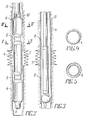
- Fig. 2 eine Bohrung mit einem in dieser eingebauten Profilrohr, dessen mittlerer Teil nach dem Abrichten einen Außendurchmesser aufweist, der kleiner als der Bohrlochdurchmesser ist (Längsschnitt);
- Fig. 3 eine Bohrung mit einer in der Komplikationszone eingebauten Profilrohrtour;
- Fig. 4 einen Schnitt nach Linie IV-IV der Fig. 2;
- Fig. 5 einen Schnitt nach Linie V-V der Fig. 2.
- Das Verfahren zum Bau einer Mehrrohrtoubohrung wird in folgender Reihenfolge durchgeführt.
- Es wird eine Bohrung mit einem Meiβel groβen Durchmessers niedergebracht und mit einer Leit-Futterrohrtour verfestigt. Dann bohrt man mit einem Meiβel kleineren Durchmessers weiter und verfestigt man erneut mit einer Futterrohrtour, die als Konduktor bezeichnet wird. Dann bohrt man bis zur projektierten Tiefe mit einem Meiβel ein und desselben Durchmessers, wobei vor dem Aufschluß der hinsichtlich der Bohrbedingungen unverträglichen Schichten oberhalb des Meiβels ein Räumer angeordnet wird, mit dossen Hilfe der Durchmesser der Bohrung, die vom Meiβel gebohrt wurde, bis zu einem Durchmesser erweitert wird, der dem Auβendurchmesser der aufgeweiteten Profilrohre gleich ist. Dann baut man an dem Bohrgestänge in die Zone der hinsichtlich der Bohrbedingungen unverträglichen Schicht eine Profilrohrtour ein, weitet man diese durch den Druck einer in diese einzupressenden Flüssigkeit auf und kalibriert den Durchgangsquerschnitt der Rohre mittels einer Aufwalzvorrichtung bis zu einem Durchmesser, der einen freien Durchgang des Meiβels zum weiteren Bohren gewahrleistet. Ahnlich werden alle darauffolgenden hinsichtlich der Bohrbedingungen unverträglichen Schichten und Komplikationszonen beim Niederbringen der Bohrung bis zur projektierten Tiefe aufgeschlossen und verfestigt, wonach in die Bohrung eine Förderrohrtour eingebaut und zementiert wird.
- Wird eine Schicht mit einem Druck, der die Zerdrückungsfestigkeit der Profilrohre übersteigt, durch Bohren aufgeschlossen, so werden zwischen diesen Profilrohre untergebracht, deren Außendurchmesser vor dem Profilieren derselben kleiner als Bohrlochdurchmesser ist; dabei ist die Länge der Profilrohre etwas größer als die Komplikationszone mit anomal hohem Lagerstättendruck, und sie werden bis zu einem Durchmesser aufgewalzt, der den Ausgangsdurchmesser der Rohre vor deren Profilierung um 3 bis 5% übersteigt.
- Das erfindungsgemäβe Verfahren zum Bau der Bohrung kann man am folgenden Beispiel veranschaulichen.
- In Übereinstimmung mit dem Projekt für das Niederbringen der Bohrung wurde das Bohren für eine Leit-Futterrohrtour 1 (Fig. 1) mittels eines Meiβels mit 394 mm Durchmesser bis zu einer Tiefe von 6 m durchgeführt, und die Bohrung wurde mit herkömmlichen Futterrphren mit 324 mm Außendurchmesser verfestigt. Dann wurde das Bohren mit einem Meiβel mit 295 mm Durchmesser bis zu einer Tiefe von 300 mm unter Spülung mit einer Bohrspülung von 1,1 g/cm3 Dichte fortgesetzt, und die Bohrung wurde mit einem Konduktor 2 mit 245 mm Durchmesser verfestigt. Dann wurde das Bohren mittels eines Meiβels mit 215,9 mm Durchmesser bis zur projektierten Tiefe der Bohrung von 1800 m durchgeführt. Dabei wurde die Zone 3 des Wasseraustritts in einer Tiefe von 460 bis 470 m mit Profilrohren 4 abgedichtet, die ohne Reduzierung des Bohrlochdurchmessers in einem Intervall von 380 bis 480 m durch Abrichten derselben mittels eines Druckes von 10 bis 12 MPa der von innen einwirkenden Flüssigkeit und anschließendes Andrücken durch Aufwalzen an die Wandunben des Bohrloches eingebaut wurden, das vorher mittels eines Räumers bis zu einem Durchmesser von 235 mm erweitert wurde.
- Die Zonen 31 des Erdölaustrittes und des Wasseraustrittes wurden in einer Tiefe von 600 bis 640 m nach einem ähnlichen Verfahren abgedichtet. Die Profilrohre 41 wurden in einem Interwall von 534 bis 650 m eingebaut.
- Die Zone 311 des Wasseraustrittes wurde in einer Tiefe von 820 bis 840 m ebenfalls mittels der Profilrohre 411 in einem Intervall von 800 bis 900 m abgedichtet.
- Des weiteren wurde das Bohren mit Hilfe eines Meiβels mit 215,5 mm Durchmesser unter Verwendung einer Bohrspülung mit einer Dichte, die den geologischen Verhältnissen einer aufzuschließenden produktiven Schicht 5 entspricht, und zwar mit einer Dichte von 1,43 g/cm3, fortgesetzt- und und es wurde eine Förderrohrtour 6 mit einem Durchmesser von 146 mm eingebaut. In den Tiefen von 330 bis 800 m wurde unter Verwendung einer Bohrspülung mit einer Dichte von 1,29 g/cm3 und in der Tiefe von 800 bis 900 m - mit einer Dichte von 1,6 g/cm3 gebohrt.
- Auf diese Weise wurde die Abdichtung der Komplikationszonen 3, 31, 311 je nach dem Aufschluß derselben durch den Einbau der Profilrohrtouren 4, 4I und 4II durchgeführt, deren Gesamtlänge 266 m betrug.
- Beim Aufschluβ einer Schicht 7 (Fig. 2, 3) mit einem anomal hohen Lagerstättendruck werden die Enden des mittleren Profilrohres 4 in der Zone der Schicht 7 mit Packerelementen 3 versehen und mit dem unteren Profilrohr 4, das mit einem Schuh 9 versehen ist, sowie mit dem oberen Profilrohr 4 verbunden, das ein linksgängiges Anschluβgewinde 10 an seinem oberen Ende aufweist.
- Der Satz von Profilrohren 4 wird an einem Bohrgestänge 11 bis zur Komplikationszone 7 mit einem anomal hohen Lagerstättendruck eingebaut, so daβ dieser Zone 7 gegenüber der mittlere zu verfestigende Teil 3 des Profilrohres untergebracht wird, wobei der Durchmesser des Umkreises desselben um 3 bis 5% kleiner als der Bohrlochdurchmesser in der vorher erweiterten Zone 7 ist, während der Durchmesser des unteren und des oberen Teil des Satzes von Rohren 4 dem Durchmesser des erweiterten Teils der Bohrung in der Komplikationszone 7 gleich ist.
- Nach dem Einbau des Satzes von Profilrohren 4 in die Komplikationszone 7 wird im Innenraum dieser Rohre ein überdruck durch Einpressen einer Flüssigkeit mit Hilfe z. B. einer Spülpumpe oder eines Zementieraggregates erzeugt; unter der Wirkung dieses Überdruckes vollziehen sich das Abrichten und die Fixierung des Oberteils und des Unterteils des Satzes von Rohren 4. Der mittlere Teil des Rohres 4, der abgerichtet wird, reicht dabei bis zum Durchmesser des erweiterten Teils der Bohrung um 3 bis 5 % nicht. Dann wird die Druckentlastung vorgenommen, das Bohrgestänge 11 wird von dem oberen Profilrohr 4 abgeschraubt und ausgebaut. Anschließend wird an dem Bohrgestänge 11 eine Aufwalzvorrichtung 12 (Fig. 3) eingefahren und, angefangen vom oberen Teil, werden die Profilrohre 4 aufgewalzt; dadurch werden das obere und das untere Rohr 4 kalibriert, während das mittlere Rohr bis zu einem Durchmesser aufgewalzt wird, der den Durchmesser dieses Rohres vor dem Profilieren um 3 bis 5 % übersteigt.
- Dabei wird das mittlere Rohr 4 aufgeweitet und dicht an die Bohrlochwandungen angedrückt, während die Packerelemente 8 die abzudichtende Zone 7 der Bohrung von dem übrigen Teil derselben (Fig. 3, 4) trennt. Zum Abschluβ der Kalibrierungsstufe des unteren Profilrohres 4 wird von diesem Rohr der Schuh 9 gelöst.
- Bei Aufwalzen der Innenfläche des mittleren. Rohres 4 der Profilrohrtour 4 vollzieht sich seine Verformung in radialer Richtung, was zu einer Metallverfestigung führt, die in einer Erhöhung der Metallhärte zum Ausdruck kommt. Der Härtezuwachs beträgt in Abhängigkeit von der Stahlsorte und der Wanddicke 130 bis 260 %.
- Die Erfindung kann . zur überdeckung von Schichten mit anomalen Lagerstättendrücken sowie zur Uberdeckung der Zonen des Nachfallens von Gestein oder des Steinfalls in der Bohrung und der Komplikationszonen angewendet werden, die durch einen intensiven Spülungsverlust, Flüssigkeits- oder Gasdurchflüsse aus aufgeschlossenen Schichten gekennzeichnet sind, welche sich mit vorhandenen Mittels nicht abdichten lassen.
Claims (3)
Applications Claiming Priority (3)
| Application Number | Priority Date | Filing Date | Title |
|---|---|---|---|
| SU884366623A SU1679030A1 (ru) | 1988-01-21 | 1988-01-21 | Способ изол ции зон осложнений в скважине профильными перекрывател ми |
| SU4366623 | 1988-01-21 | ||
| PCT/SU1988/000234 WO1989006739A1 (fr) | 1988-01-21 | 1988-11-22 | Procede pour construire un puits |
Publications (3)
| Publication Number | Publication Date |
|---|---|
| EP0353309A1 true EP0353309A1 (de) | 1990-02-07 |
| EP0353309A4 EP0353309A4 (en) | 1991-05-08 |
| EP0353309B1 EP0353309B1 (de) | 1997-02-05 |
Family
ID=21350919
Family Applications (1)
| Application Number | Title | Priority Date | Filing Date |
|---|---|---|---|
| EP89901623A Expired - Lifetime EP0353309B1 (de) | 1988-01-21 | 1988-11-22 | Verfahren zum bau eines lochs |
Country Status (13)
| Country | Link |
|---|---|
| US (1) | US4976322A (de) |
| EP (1) | EP0353309B1 (de) |
| JP (1) | JP2530737B2 (de) |
| CN (1) | CN1015808B (de) |
| AU (1) | AU606777B2 (de) |
| CA (1) | CA1301635C (de) |
| DE (1) | DE3855787D1 (de) |
| HU (1) | HUT57371A (de) |
| IN (1) | IN170723B (de) |
| MX (1) | MX171802B (de) |
| NO (1) | NO300986B1 (de) |
| SU (1) | SU1679030A1 (de) |
| WO (1) | WO1989006739A1 (de) |
Cited By (4)
| Publication number | Priority date | Publication date | Assignee | Title |
|---|---|---|---|---|
| WO1993025799A1 (en) * | 1992-06-09 | 1993-12-23 | Shell Internationale Research Maatschappij B.V. | Method of creating a wellbore in an underground formation |
| US6446724B2 (en) | 1999-05-20 | 2002-09-10 | Baker Hughes Incorporated | Hanging liners by pipe expansion |
| US7121351B2 (en) | 2000-10-25 | 2006-10-17 | Weatherford/Lamb, Inc. | Apparatus and method for completing a wellbore |
| US7367389B2 (en) | 2003-06-16 | 2008-05-06 | Weatherford/Lamb, Inc. | Tubing expansion |
Families Citing this family (116)
| Publication number | Priority date | Publication date | Assignee | Title |
|---|---|---|---|---|
| WO1990005833A1 (fr) * | 1988-11-22 | 1990-05-31 | Tatarsky Gosudarstvenny Nauchno-Issledovatelsky I Proektny Institut Neftyanoi Promyshlennosti | Dispositif pour obturer une zone de complications dans un puits |
| WO1995003476A1 (en) * | 1993-07-23 | 1995-02-02 | Tatarsky Gosudarstvenny Nauchno-Issledovatelsky I Proektny Institut Neftyanoi Promyshlennosti | Method of finishing wells |
| US6868906B1 (en) | 1994-10-14 | 2005-03-22 | Weatherford/Lamb, Inc. | Closed-loop conveyance systems for well servicing |
| US6085838A (en) * | 1997-05-27 | 2000-07-11 | Schlumberger Technology Corporation | Method and apparatus for cementing a well |
| GB9714651D0 (en) | 1997-07-12 | 1997-09-17 | Petroline Wellsystems Ltd | Downhole tubing |
| MY122241A (en) * | 1997-08-01 | 2006-04-29 | Shell Int Research | Creating zonal isolation between the interior and exterior of a well system |
| US6029748A (en) * | 1997-10-03 | 2000-02-29 | Baker Hughes Incorporated | Method and apparatus for top to bottom expansion of tubulars |
| US6021850A (en) * | 1997-10-03 | 2000-02-08 | Baker Hughes Incorporated | Downhole pipe expansion apparatus and method |
| US6098717A (en) * | 1997-10-08 | 2000-08-08 | Formlock, Inc. | Method and apparatus for hanging tubulars in wells |
| US6098710A (en) * | 1997-10-29 | 2000-08-08 | Schlumberger Technology Corporation | Method and apparatus for cementing a well |
| GB9723031D0 (en) | 1997-11-01 | 1998-01-07 | Petroline Wellsystems Ltd | Downhole tubing location method |
| US6354373B1 (en) | 1997-11-26 | 2002-03-12 | Schlumberger Technology Corporation | Expandable tubing for a well bore hole and method of expanding |
| US6073692A (en) * | 1998-03-27 | 2000-06-13 | Baker Hughes Incorporated | Expanding mandrel inflatable packer |
| US6263972B1 (en) | 1998-04-14 | 2001-07-24 | Baker Hughes Incorporated | Coiled tubing screen and method of well completion |
| US6026900A (en) * | 1998-06-15 | 2000-02-22 | Keller; Carl E. | Multiple liner method for borehole access |
| US6745845B2 (en) | 1998-11-16 | 2004-06-08 | Shell Oil Company | Isolation of subterranean zones |
| US6823937B1 (en) | 1998-12-07 | 2004-11-30 | Shell Oil Company | Wellhead |
| US7231985B2 (en) | 1998-11-16 | 2007-06-19 | Shell Oil Company | Radial expansion of tubular members |
| US6575240B1 (en) | 1998-12-07 | 2003-06-10 | Shell Oil Company | System and method for driving pipe |
| US6557640B1 (en) | 1998-12-07 | 2003-05-06 | Shell Oil Company | Lubrication and self-cleaning system for expansion mandrel |
| US6712154B2 (en) | 1998-11-16 | 2004-03-30 | Enventure Global Technology | Isolation of subterranean zones |
| US7121352B2 (en) | 1998-11-16 | 2006-10-17 | Enventure Global Technology | Isolation of subterranean zones |
| US7357188B1 (en) | 1998-12-07 | 2008-04-15 | Shell Oil Company | Mono-diameter wellbore casing |
| US7603758B2 (en) | 1998-12-07 | 2009-10-20 | Shell Oil Company | Method of coupling a tubular member |
| GB2343691B (en) | 1998-11-16 | 2003-05-07 | Shell Int Research | Isolation of subterranean zones |
| US6640903B1 (en) | 1998-12-07 | 2003-11-04 | Shell Oil Company | Forming a wellbore casing while simultaneously drilling a wellbore |
| US6604763B1 (en) | 1998-12-07 | 2003-08-12 | Shell Oil Company | Expandable connector |
| AU6981001A (en) | 1998-11-16 | 2002-01-02 | Shell Oil Co | Radial expansion of tubular members |
| US6634431B2 (en) | 1998-11-16 | 2003-10-21 | Robert Lance Cook | Isolation of subterranean zones |
| US7185710B2 (en) | 1998-12-07 | 2007-03-06 | Enventure Global Technology | Mono-diameter wellbore casing |
| US7363984B2 (en) | 1998-12-07 | 2008-04-29 | Enventure Global Technology, Llc | System for radially expanding a tubular member |
| US7195064B2 (en) | 1998-12-07 | 2007-03-27 | Enventure Global Technology | Mono-diameter wellbore casing |
| US6739392B2 (en) | 1998-12-07 | 2004-05-25 | Shell Oil Company | Forming a wellbore casing while simultaneously drilling a wellbore |
| GB2344606B (en) | 1998-12-07 | 2003-08-13 | Shell Int Research | Forming a wellbore casing by expansion of a tubular member |
| US7552776B2 (en) | 1998-12-07 | 2009-06-30 | Enventure Global Technology, Llc | Anchor hangers |
| CA2310878A1 (en) | 1998-12-07 | 2000-12-07 | Shell Internationale Research Maatschappij B.V. | Lubrication and self-cleaning system for expansion mandrel |
| CA2356131C (en) | 1998-12-22 | 2008-01-29 | Weatherford/Lamb, Inc. | Downhole sealing for production tubing |
| GB0224807D0 (en) | 2002-10-25 | 2002-12-04 | Weatherford Lamb | Downhole filter |
| US7188687B2 (en) | 1998-12-22 | 2007-03-13 | Weatherford/Lamb, Inc. | Downhole filter |
| DE69926802D1 (de) * | 1998-12-22 | 2005-09-22 | Weatherford Lamb | Verfahren und vorrichtung zum profilieren und verbinden von rohren |
| AU770359B2 (en) | 1999-02-26 | 2004-02-19 | Shell Internationale Research Maatschappij B.V. | Liner hanger |
| US6415863B1 (en) | 1999-03-04 | 2002-07-09 | Bestline Liner System, Inc. | Apparatus and method for hanging tubulars in wells |
| US7055608B2 (en) | 1999-03-11 | 2006-06-06 | Shell Oil Company | Forming a wellbore casing while simultaneously drilling a wellbore |
| CA2306656C (en) | 1999-04-26 | 2006-06-06 | Shell Internationale Research Maatschappij B.V. | Expandable connector for borehole tubes |
| US7350563B2 (en) | 1999-07-09 | 2008-04-01 | Enventure Global Technology, L.L.C. | System for lining a wellbore casing |
| GB9921557D0 (en) | 1999-09-14 | 1999-11-17 | Petroline Wellsystems Ltd | Downhole apparatus |
| US7048067B1 (en) | 1999-11-01 | 2006-05-23 | Shell Oil Company | Wellbore casing repair |
| GC0000211A (en) | 1999-11-15 | 2006-03-29 | Shell Int Research | Expanding a tubular element in a wellbore |
| US7516790B2 (en) | 1999-12-03 | 2009-04-14 | Enventure Global Technology, Llc | Mono-diameter wellbore casing |
| US7234531B2 (en) | 1999-12-03 | 2007-06-26 | Enventure Global Technology, Llc | Mono-diameter wellbore casing |
| US6325148B1 (en) | 1999-12-22 | 2001-12-04 | Weatherford/Lamb, Inc. | Tools and methods for use with expandable tubulars |
| US6598678B1 (en) | 1999-12-22 | 2003-07-29 | Weatherford/Lamb, Inc. | Apparatus and methods for separating and joining tubulars in a wellbore |
| US6708769B2 (en) | 2000-05-05 | 2004-03-23 | Weatherford/Lamb, Inc. | Apparatus and methods for forming a lateral wellbore |
| US7100684B2 (en) | 2000-07-28 | 2006-09-05 | Enventure Global Technology | Liner hanger with standoffs |
| CA2466685C (en) | 2000-09-18 | 2010-11-23 | Shell Oil Company | Liner hanger with sliding sleeve valve |
| WO2002029199A1 (en) | 2000-10-02 | 2002-04-11 | Shell Oil Company | Method and apparatus for casing expansion |
| US7100685B2 (en) | 2000-10-02 | 2006-09-05 | Enventure Global Technology | Mono-diameter wellbore casing |
| US7090025B2 (en) * | 2000-10-25 | 2006-08-15 | Weatherford/Lamb, Inc. | Methods and apparatus for reforming and expanding tubulars in a wellbore |
| CA2428819A1 (en) * | 2001-01-03 | 2002-07-11 | Enventure Global Technology | Mono-diameter wellbore casing |
| US7410000B2 (en) | 2001-01-17 | 2008-08-12 | Enventure Global Technology, Llc. | Mono-diameter wellbore casing |
| CN1323221C (zh) * | 2001-03-09 | 2007-06-27 | 住友金属工业株式会社 | 一种扩管钢管及油井用钢管的埋设方法 |
| US7172027B2 (en) | 2001-05-15 | 2007-02-06 | Weatherford/Lamb, Inc. | Expanding tubing |
| GB2394979B (en) | 2001-07-06 | 2005-11-02 | Eventure Global Technology | Liner hanger |
| AU2002318438A1 (en) | 2001-07-06 | 2003-01-21 | Enventure Global Technology | Liner hanger |
| US7258168B2 (en) | 2001-07-27 | 2007-08-21 | Enventure Global Technology L.L.C. | Liner hanger with slip joint sealing members and method of use |
| US20080093068A1 (en) * | 2001-09-06 | 2008-04-24 | Enventure Global Technology | System for Lining a Wellbore Casing |
| US7793721B2 (en) | 2003-03-11 | 2010-09-14 | Eventure Global Technology, Llc | Apparatus for radially expanding and plastically deforming a tubular member |
| WO2003023178A2 (en) | 2001-09-07 | 2003-03-20 | Enventure Global Technology | Adjustable expansion cone assembly |
| GB2421258B (en) | 2001-11-12 | 2006-08-09 | Enventure Global Technology | Mono diameter wellbore casing |
| US7066284B2 (en) | 2001-11-14 | 2006-06-27 | Halliburton Energy Services, Inc. | Method and apparatus for a monodiameter wellbore, monodiameter casing, monobore, and/or monowell |
| GB0131019D0 (en) * | 2001-12-27 | 2002-02-13 | Weatherford Lamb | Bore isolation |
| WO2003058022A2 (en) | 2001-12-27 | 2003-07-17 | Enventure Global Technology | Seal receptacle using expandable liner hanger |
| US7377326B2 (en) | 2002-08-23 | 2008-05-27 | Enventure Global Technology, L.L.C. | Magnetic impulse applied sleeve method of forming a wellbore casing |
| WO2004027786A2 (en) | 2002-09-20 | 2004-04-01 | Enventure Global Technology | Protective sleeve for expandable tubulars |
| US7424918B2 (en) | 2002-08-23 | 2008-09-16 | Enventure Global Technology, L.L.C. | Interposed joint sealing layer method of forming a wellbore casing |
| US6732806B2 (en) | 2002-01-29 | 2004-05-11 | Weatherford/Lamb, Inc. | One trip expansion method and apparatus for use in a wellbore |
| EP1985797B1 (de) | 2002-04-12 | 2011-10-26 | Enventure Global Technology | Schutzhülse für Gewindeverbindungen für eine ausdehnbare Liner-Aufhängvorrichtung |
| CA2482278A1 (en) | 2002-04-15 | 2003-10-30 | Enventure Global Technology | Protective sleeve for threaded connections for expandable liner hanger |
| GB2406125B (en) | 2002-05-29 | 2006-11-01 | Enventure Global Technology | Radially expanding a tubular member |
| AU2003274310A1 (en) | 2002-06-10 | 2003-12-22 | Enventure Global Technology | Mono-diameter wellbore casing |
| AU2003263852A1 (en) | 2002-09-20 | 2004-04-08 | Enventure Global Technology | Self-lubricating expansion mandrel for expandable tubular |
| CA2499007C (en) | 2002-09-20 | 2012-08-07 | Enventure Global Technology | Bottom plug for forming a mono diameter wellbore casing |
| US7739917B2 (en) | 2002-09-20 | 2010-06-22 | Enventure Global Technology, Llc | Pipe formability evaluation for expandable tubulars |
| WO2006088743A2 (en) * | 2005-02-14 | 2006-08-24 | Enventure Global Technology, L.L.C. | Radial expansion of a wellbore casing against a formation |
| US7886831B2 (en) | 2003-01-22 | 2011-02-15 | Enventure Global Technology, L.L.C. | Apparatus for radially expanding and plastically deforming a tubular member |
| JP2006517011A (ja) | 2003-01-27 | 2006-07-13 | エンベンチャー グローバル テクノロジー | 管状部材放射状拡大用潤滑システム |
| GB2429996B (en) | 2003-02-26 | 2007-08-29 | Enventure Global Technology | Apparatus for radially expanding and plastically deforming a tubular member |
| GB2415988B (en) | 2003-04-17 | 2007-10-17 | Enventure Global Technology | Apparatus for radially expanding and plastically deforming a tubular member |
| US7213643B2 (en) * | 2003-04-23 | 2007-05-08 | Halliburton Energy Services, Inc. | Expanded liner system and method |
| US7441606B2 (en) * | 2003-05-01 | 2008-10-28 | Weatherford/Lamb, Inc. | Expandable fluted liner hanger and packer system |
| RU2236557C1 (ru) * | 2003-05-29 | 2004-09-20 | Салахов Минзагит Мукатдисович | Устройство для отключения пластов друг от друга в скважине (варианты) |
| US20050166387A1 (en) | 2003-06-13 | 2005-08-04 | Cook Robert L. | Method and apparatus for forming a mono-diameter wellbore casing |
| US7712522B2 (en) | 2003-09-05 | 2010-05-11 | Enventure Global Technology, Llc | Expansion cone and system |
| US7308944B2 (en) | 2003-10-07 | 2007-12-18 | Weatherford/Lamb, Inc. | Expander tool for use in a wellbore |
| RU2265115C1 (ru) * | 2004-05-24 | 2005-11-27 | Открытое акционерное общество "Татнефть" им. В.Д. Шашина | Способ установки перекрывателя из профильных и цилиндрических труб в скважине |
| RU2270323C1 (ru) * | 2004-07-16 | 2006-02-20 | Открытое акционерное общество "Татнефть" им. В.Д. Шашина | Устройство для перекрытия зон осложнения бурения в скважине |
| US7819185B2 (en) | 2004-08-13 | 2010-10-26 | Enventure Global Technology, Llc | Expandable tubular |
| GB2419148B (en) * | 2004-10-12 | 2009-07-01 | Weatherford Lamb | Methods and apparatus for manufacturing of expandable tubular |
| CN101238272B (zh) * | 2005-07-22 | 2013-11-13 | 国际壳牌研究有限公司 | 形成井下环形阻挡层的装置和方法 |
| CA2555563C (en) | 2005-08-05 | 2009-03-31 | Weatherford/Lamb, Inc. | Apparatus and methods for creation of down hole annular barrier |
| RU2307231C1 (ru) * | 2006-03-27 | 2007-09-27 | Открытое акционерное общество "Татнефть" им. В.Д. Шашина | Способ ремонта обсадных колонн в скважинах |
| RU2307916C1 (ru) * | 2006-04-05 | 2007-10-10 | Открытое акционерное общество "Татнефть" им. В.Д. Шашина | Способ установки профильного перекрывателя в скважине |
| RU2315854C1 (ru) * | 2006-05-15 | 2008-01-27 | Общество с ограниченной ответственностью "Нефтяник" | Устройство для отключения пластов друг от друга в скважине |
| RU2315170C1 (ru) * | 2006-07-04 | 2008-01-20 | Открытое акционерное общество "Татнефть" им. В.Д. Шашина | Способ установки профильного перекрывателя в скважине |
| RU2335617C1 (ru) * | 2007-02-28 | 2008-10-10 | Открытое акционерное общество "Татнефть" им. В.Д. Шашина | Способ изоляции зон осложнений в скважине профильным перекрывателем |
| RU2339786C1 (ru) * | 2007-04-06 | 2008-11-27 | Открытое акционерное общество "Татнефть" им. В.Д. Шашина | Способ установки профильного перекрывателя в скважине |
| RU2346139C1 (ru) * | 2007-06-26 | 2009-02-10 | Открытое акционерное общество "Татнефть" им. В.Д. Шашина | Способ установки профильного перекрывателя в скважине |
| CA2715647C (en) | 2008-02-19 | 2013-10-01 | Weatherford/Lamb, Inc. | Expandable packer |
| US9551201B2 (en) | 2008-02-19 | 2017-01-24 | Weatherford Technology Holdings, Llc | Apparatus and method of zonal isolation |
| RU2379464C1 (ru) * | 2008-09-09 | 2010-01-20 | Открытое акционерное общество "Татнефть" им. В.Д. Шашина | Способ установки профильного перекрывателя в скважине |
| GB0823194D0 (en) * | 2008-12-19 | 2009-01-28 | Tunget Bruce A | Controlled Circulation work string for well construction |
| RU2386780C1 (ru) * | 2009-02-03 | 2010-04-20 | Открытое акционерное общество "Татнефть" им. В.Д. Шашина | Способ поинтервального вскрытия и крепления осложненных участков ствола скважины |
| US8360142B2 (en) * | 2009-06-15 | 2013-01-29 | Enventure Global Technology, Llc | High-ratio tubular expansion |
| RU2471969C1 (ru) * | 2011-07-08 | 2013-01-10 | Открытое акционерное общество "Татнефть" имени В.Д. Шашина | Способ крепления необсаженной части скважины методом диапазонного расширения труб |
| CN103161405B (zh) * | 2013-03-03 | 2015-07-29 | 中国矿业大学 | 矿用井下探放高压岩溶水钻孔施工的套管隔离地层破碎带方法 |
| US9453393B2 (en) | 2014-01-22 | 2016-09-27 | Seminole Services, LLC | Apparatus and method for setting a liner |
Family Cites Families (12)
| Publication number | Priority date | Publication date | Assignee | Title |
|---|---|---|---|---|
| US2237538A (en) * | 1939-02-25 | 1941-04-08 | John A Zublin | Swedge |
| US2214226A (en) * | 1939-03-29 | 1940-09-10 | English Aaron | Method and apparatus useful in drilling and producing wells |
| US2447629A (en) * | 1944-05-23 | 1948-08-24 | Richfield Oil Corp | Apparatus for forming a section of casing below casing already in position in a well hole |
| US3134442A (en) * | 1958-10-27 | 1964-05-26 | Pan American Petroleum Corp | Apparatus for lining wells |
| US3054455A (en) * | 1959-08-31 | 1962-09-18 | Keltner Haskell Owen | Tool for sealing a fissure along a mine shaft |
| US3191677A (en) * | 1963-04-29 | 1965-06-29 | Myron M Kinley | Method and apparatus for setting liners in tubing |
| US3326293A (en) * | 1964-06-26 | 1967-06-20 | Wilson Supply Company | Well casing repair |
| SU907220A1 (ru) * | 1980-05-21 | 1982-02-23 | Татарский Научно-Исследовательский И Проектныий Институт Нефтяной Промышленности | Способ установки профильного перекрывател в скважине |
| US4483399A (en) * | 1981-02-12 | 1984-11-20 | Colgate Stirling A | Method of deep drilling |
| SU1010252A1 (ru) * | 1982-01-21 | 1983-04-07 | Полтавское Отделение Украинского Научно-Исследовательского Геологоразведочного Института Министерства Геологии Усср | Способ креплени осложненных зон скважин |
| SU1008419A1 (ru) * | 1982-02-25 | 1983-03-30 | Ивано-Франковский Институт Нефти И Газа | Устройство дл локального креплени ствола скважины |
| US4501327A (en) * | 1982-07-19 | 1985-02-26 | Philip Retz | Split casing block-off for gas or water in oil drilling |
-
1988
- 1988-01-21 SU SU884366623A patent/SU1679030A1/ru active
- 1988-11-22 JP JP1501552A patent/JP2530737B2/ja not_active Expired - Lifetime
- 1988-11-22 WO PCT/SU1988/000234 patent/WO1989006739A1/ru not_active Ceased
- 1988-11-22 EP EP89901623A patent/EP0353309B1/de not_active Expired - Lifetime
- 1988-11-22 US US07/423,418 patent/US4976322A/en not_active Expired - Lifetime
- 1988-11-22 DE DE3855787T patent/DE3855787D1/de not_active Expired - Fee Related
- 1988-11-22 AU AU29395/89A patent/AU606777B2/en not_active Ceased
- 1988-11-22 HU HU89982A patent/HUT57371A/hu unknown
-
1989
- 1989-01-13 IN IN38/CAL/89A patent/IN170723B/en unknown
- 1989-01-20 CN CN89100302A patent/CN1015808B/zh not_active Expired
- 1989-01-23 CA CA000588874A patent/CA1301635C/en not_active Expired - Lifetime
- 1989-01-23 MX MX014920A patent/MX171802B/es unknown
- 1989-09-19 NO NO893732A patent/NO300986B1/no not_active IP Right Cessation
Cited By (8)
| Publication number | Priority date | Publication date | Assignee | Title |
|---|---|---|---|---|
| WO1993025799A1 (en) * | 1992-06-09 | 1993-12-23 | Shell Internationale Research Maatschappij B.V. | Method of creating a wellbore in an underground formation |
| US6446724B2 (en) | 1999-05-20 | 2002-09-10 | Baker Hughes Incorporated | Hanging liners by pipe expansion |
| US6561271B2 (en) | 1999-05-20 | 2003-05-13 | Baker Hughes Incorporated | Hanging liners by pipe expansion |
| US6598677B1 (en) | 1999-05-20 | 2003-07-29 | Baker Hughes Incorporated | Hanging liners by pipe expansion |
| US6631765B2 (en) | 1999-05-20 | 2003-10-14 | Baker Hughes Incorporated | Hanging liners by pipe expansion |
| US6915852B2 (en) | 1999-05-20 | 2005-07-12 | Baker Hughes Incorporated | Hanging liners by pipe expansion |
| US7121351B2 (en) | 2000-10-25 | 2006-10-17 | Weatherford/Lamb, Inc. | Apparatus and method for completing a wellbore |
| US7367389B2 (en) | 2003-06-16 | 2008-05-06 | Weatherford/Lamb, Inc. | Tubing expansion |
Also Published As
| Publication number | Publication date |
|---|---|
| IN170723B (de) | 1992-05-09 |
| CA1301635C (en) | 1992-05-26 |
| CN1015808B (zh) | 1992-03-11 |
| JP2530737B2 (ja) | 1996-09-04 |
| MX171802B (es) | 1993-11-15 |
| AU2939589A (en) | 1989-08-11 |
| DE3855787D1 (de) | 1997-03-20 |
| AU606777B2 (en) | 1991-02-14 |
| NO893732L (no) | 1989-09-19 |
| HUT57371A (en) | 1991-11-28 |
| SU1679030A1 (ru) | 1991-09-23 |
| WO1989006739A1 (fr) | 1989-07-27 |
| NO893732D0 (no) | 1989-09-19 |
| EP0353309B1 (de) | 1997-02-05 |
| HU890982D0 (en) | 1990-12-28 |
| US4976322A (en) | 1990-12-11 |
| JPH02503097A (ja) | 1990-09-27 |
| NO300986B1 (no) | 1997-08-25 |
| EP0353309A4 (en) | 1991-05-08 |
| CN1034973A (zh) | 1989-08-23 |
Similar Documents
| Publication | Publication Date | Title |
|---|---|---|
| EP0353309A1 (de) | Verfahren zum bau eines lochs | |
| EP0397870B1 (de) | Verfahren zur befestigung der produktiven schicht innerhalb einer bohrung | |
| DE69602170T2 (de) | Verfahren zur herstellung einer verrohrung im bohrloch | |
| DE3687166T2 (de) | Verfahren und vorrichtung zum auskleiden einer bohrlochswand. | |
| EP0397874B1 (de) | Vorrichtung zum schliessen einer schwierigkeitszone in einem bohrloch | |
| DE3125035C2 (de) | ||
| DE69808139T2 (de) | Verfahren zum herstellen und verrohren von ölproduktionsbohrlöchern | |
| DE69009352T2 (de) | Verfahren zur Filterkiesfüllung für ein Bohrloch. | |
| DE19725996C2 (de) | Verfahren und Bohrlochsystem zur Förderung von Wasser aus einem im wesentlichen vertikalen Bohrloch | |
| DE4393857C2 (de) | Verfahren und Vorrichtung zum Abdichten der Stoßstelle zwischen einem Hauptbohrloch und einem Zweigbohrloch | |
| DE3103762A1 (de) | Einrichtung zum regeln der geschwindigkeit einer geraetebewegung in der verrohrung eines bohrlochs | |
| EP2357317B1 (de) | Verfahren zur Sanierung einer Erdreich-Bohrung | |
| EP0345256B1 (de) | Verfahren zum herstellen eines brunnens | |
| DE102011085540B3 (de) | Vorrichtung und Verfahren zum Verschließen von Bohrlochmündungen sowie Verwendung der Vorrichtung | |
| EP0177623A1 (de) | Verfahren und Einrichtung zur Anfertigung von insbesondere wasserfördernden Bohrbrunnen | |
| EP1961871A1 (de) | Herstellungsverfahren eines Horizontalfilterbrunnen und Brunnen an sich | |
| DE3703534C2 (de) | ||
| DE19721361C2 (de) | Verfahren zur Herstellung von Pfählen und solchermaßen hergestellte Pfähle | |
| EP1915505B1 (de) | Verfahren und vorrichtung zum aufheben einer blockierung einer bohrkrone beim bohren | |
| DE3543059C2 (de) | ||
| AT389135B (de) | Filterbrunnen | |
| DE3307392A1 (de) | Verfahren zum bau einer mit beton ausgekleideten untertagekammer | |
| DE10005941C2 (de) | Imlochhammerschnecke mit Betonierrohr | |
| DE1928471A1 (de) | Verfahren und Vorrichtung zur Verdichtung und Entwaesserung von Boeden | |
| AT408472B (de) | Verfahren und einrichtung zum bohren und auskleiden von löchern |
Legal Events
| Date | Code | Title | Description |
|---|---|---|---|
| PUAI | Public reference made under article 153(3) epc to a published international application that has entered the european phase |
Free format text: ORIGINAL CODE: 0009012 |
|
| 17P | Request for examination filed |
Effective date: 19890925 |
|
| AK | Designated contracting states |
Kind code of ref document: A1 Designated state(s): DE FR GB IT |
|
| A4 | Supplementary search report drawn up and despatched |
Effective date: 19910319 |
|
| AK | Designated contracting states |
Kind code of ref document: A4 Designated state(s): DE FR GB IT |
|
| RHK1 | Main classification (correction) |
Ipc: E21B 33/00 |
|
| 17Q | First examination report despatched |
Effective date: 19921109 |
|
| GRAG | Despatch of communication of intention to grant |
Free format text: ORIGINAL CODE: EPIDOS AGRA |
|
| GRAH | Despatch of communication of intention to grant a patent |
Free format text: ORIGINAL CODE: EPIDOS IGRA |
|
| GRAH | Despatch of communication of intention to grant a patent |
Free format text: ORIGINAL CODE: EPIDOS IGRA |
|
| ITF | It: translation for a ep patent filed | ||
| GRAA | (expected) grant |
Free format text: ORIGINAL CODE: 0009210 |
|
| AK | Designated contracting states |
Kind code of ref document: B1 Designated state(s): DE FR GB IT |
|
| GBT | Gb: translation of ep patent filed (gb section 77(6)(a)/1977) |
Effective date: 19970211 |
|
| REF | Corresponds to: |
Ref document number: 3855787 Country of ref document: DE Date of ref document: 19970320 |
|
| ET | Fr: translation filed | ||
| PLBE | No opposition filed within time limit |
Free format text: ORIGINAL CODE: 0009261 |
|
| STAA | Information on the status of an ep patent application or granted ep patent |
Free format text: STATUS: NO OPPOSITION FILED WITHIN TIME LIMIT |
|
| 26N | No opposition filed | ||
| REG | Reference to a national code |
Ref country code: GB Ref legal event code: IF02 |
|
| PGFP | Annual fee paid to national office [announced via postgrant information from national office to epo] |
Ref country code: FR Payment date: 20051125 Year of fee payment: 18 |
|
| PGFP | Annual fee paid to national office [announced via postgrant information from national office to epo] |
Ref country code: DE Payment date: 20061116 Year of fee payment: 19 |
|
| PGFP | Annual fee paid to national office [announced via postgrant information from national office to epo] |
Ref country code: GB Payment date: 20061122 Year of fee payment: 19 |
|
| PGFP | Annual fee paid to national office [announced via postgrant information from national office to epo] |
Ref country code: IT Payment date: 20061130 Year of fee payment: 19 |
|
| REG | Reference to a national code |
Ref country code: FR Ref legal event code: ST Effective date: 20070731 |
|
| PG25 | Lapsed in a contracting state [announced via postgrant information from national office to epo] |
Ref country code: FR Free format text: LAPSE BECAUSE OF NON-PAYMENT OF DUE FEES Effective date: 20061130 |
|
| GBPC | Gb: european patent ceased through non-payment of renewal fee |
Effective date: 20071122 |
|
| PG25 | Lapsed in a contracting state [announced via postgrant information from national office to epo] |
Ref country code: DE Free format text: LAPSE BECAUSE OF NON-PAYMENT OF DUE FEES Effective date: 20080603 |
|
| PG25 | Lapsed in a contracting state [announced via postgrant information from national office to epo] |
Ref country code: GB Free format text: LAPSE BECAUSE OF NON-PAYMENT OF DUE FEES Effective date: 20071122 |
|
| PG25 | Lapsed in a contracting state [announced via postgrant information from national office to epo] |
Ref country code: IT Free format text: LAPSE BECAUSE OF NON-PAYMENT OF DUE FEES Effective date: 20071122 |