EP0353364A1 - Bouton-pression - Google Patents
Bouton-pression Download PDFInfo
- Publication number
- EP0353364A1 EP0353364A1 EP88307267A EP88307267A EP0353364A1 EP 0353364 A1 EP0353364 A1 EP 0353364A1 EP 88307267 A EP88307267 A EP 88307267A EP 88307267 A EP88307267 A EP 88307267A EP 0353364 A1 EP0353364 A1 EP 0353364A1
- Authority
- EP
- European Patent Office
- Prior art keywords
- grommet
- enlargement
- shank
- button
- passage
- Prior art date
- Legal status (The legal status is an assumption and is not a legal conclusion. Google has not performed a legal analysis and makes no representation as to the accuracy of the status listed.)
- Granted
Links
- 239000004744 fabric Substances 0.000 claims abstract description 24
- 238000004873 anchoring Methods 0.000 claims description 32
- 239000000463 material Substances 0.000 description 5
- 238000003780 insertion Methods 0.000 description 3
- 230000037431 insertion Effects 0.000 description 3
- 230000000694 effects Effects 0.000 description 2
- 230000014759 maintenance of location Effects 0.000 description 2
- 239000004033 plastic Substances 0.000 description 2
- 239000000853 adhesive Substances 0.000 description 1
- 230000001070 adhesive effect Effects 0.000 description 1
- 230000004075 alteration Effects 0.000 description 1
- 239000002991 molded plastic Substances 0.000 description 1
- 230000000284 resting effect Effects 0.000 description 1
- 239000000523 sample Substances 0.000 description 1
Images
Classifications
-
- A—HUMAN NECESSITIES
- A44—HABERDASHERY; JEWELLERY
- A44B—BUTTONS, PINS, BUCKLES, SLIDE FASTENERS, OR THE LIKE
- A44B17/00—Press-button or snap fasteners
- A44B17/0064—Details
- A44B17/0082—Decoration
-
- Y—GENERAL TAGGING OF NEW TECHNOLOGICAL DEVELOPMENTS; GENERAL TAGGING OF CROSS-SECTIONAL TECHNOLOGIES SPANNING OVER SEVERAL SECTIONS OF THE IPC; TECHNICAL SUBJECTS COVERED BY FORMER USPC CROSS-REFERENCE ART COLLECTIONS [XRACs] AND DIGESTS
- Y10—TECHNICAL SUBJECTS COVERED BY FORMER USPC
- Y10S—TECHNICAL SUBJECTS COVERED BY FORMER USPC CROSS-REFERENCE ART COLLECTIONS [XRACs] AND DIGESTS
- Y10S24/00—Buckles, buttons, clasps
- Y10S24/30—Separable-fastener or required component thereof
- Y10S24/31—Separable-fastener or required component thereof with third, detached member completing interlock
- Y10S24/35—Third member includes relatively movable, separate components
-
- Y—GENERAL TAGGING OF NEW TECHNOLOGICAL DEVELOPMENTS; GENERAL TAGGING OF CROSS-SECTIONAL TECHNOLOGIES SPANNING OVER SEVERAL SECTIONS OF THE IPC; TECHNICAL SUBJECTS COVERED BY FORMER USPC CROSS-REFERENCE ART COLLECTIONS [XRACs] AND DIGESTS
- Y10—TECHNICAL SUBJECTS COVERED BY FORMER USPC
- Y10T—TECHNICAL SUBJECTS COVERED BY FORMER US CLASSIFICATION
- Y10T24/00—Buckles, buttons, clasps, etc.
- Y10T24/36—Button with fastener
- Y10T24/3651—Separable
- Y10T24/3655—Spring
- Y10T24/366—Resilient socket
-
- Y—GENERAL TAGGING OF NEW TECHNOLOGICAL DEVELOPMENTS; GENERAL TAGGING OF CROSS-SECTIONAL TECHNOLOGIES SPANNING OVER SEVERAL SECTIONS OF THE IPC; TECHNICAL SUBJECTS COVERED BY FORMER USPC CROSS-REFERENCE ART COLLECTIONS [XRACs] AND DIGESTS
- Y10—TECHNICAL SUBJECTS COVERED BY FORMER USPC
- Y10T—TECHNICAL SUBJECTS COVERED BY FORMER US CLASSIFICATION
- Y10T24/00—Buckles, buttons, clasps, etc.
- Y10T24/45—Separable-fastener or required component thereof [e.g., projection and cavity to complete interlock]
- Y10T24/45225—Separable-fastener or required component thereof [e.g., projection and cavity to complete interlock] including member having distinct formations and mating member selectively interlocking therewith
- Y10T24/45262—Pin, post and receiver
Definitions
- This invention relates to snap fasteners for attaching two clothing fabric layers together and provides a device which, while performing the above function, also serves as an attractive and suitable ornamentation to the clothing with which it is worn.
- the invention is thought to have as its principal application a replacement for the button and buttonhole which will 'button-down' the point of a button-down dress shirt collar.
- the invention does, however, have other applications.
- the general aspects of the invention are, as an example only, described in relation to the shirt collar point even though the invention has wider application.
- the invention provides a grommet for attachment to the collar point at the location where there would normally be a button hole.
- the grommet provides a passage through the collar point material.
- Anchoring means is provided on the shirt body beneath the point at the location where the button, corresponding to the buttonhole, would conventionally be sewn.
- a button which can have the outside appearance of a conventional shirt button is provided with a shank extending from its inner side.
- the shank is arranged to pass through the grommet and to leave a free end.
- the free end of the shank is arranged to make releasable attachment with anchoring means.
- the shank intermediate the button head and the free end is arranged, in combination with the grommet to make a snap action attachment to and release from the grommet.
- the button may be attached to the collar point by inserting the shank through the grommet to which it is attached by the snap action referred to. In its insertion the button head overlies and conceals the grommet.
- the free end of the shank is then attached to the anchor means to provide a 'buttoned down' point for the shirt collar.
- the button may be readily replaced by firstly, detachment with deliberate effort of the shank first from the anchor means and then from the grommet, and secondly choosing a replacement button with new shank inserted first through the grommet and then into the anchoring means.
- the outer or exposed side of the button may be alternately of conventional appearance or ornamented in any desired manner and pairs of buttons of alternate appearance may be supplied for wearing on different occasions.
- the exposed side of the button may have a conventional shirt button appearance or may be jewelled or otherwise ornamented, or have any other styled appearance.
- the invention when applied to a shirt collar, to create a 'buttoned-down' effect, produces an improved appearance over the conventional 'button-down' collar.
- conventional 'button-down' collars require soft cloth so that the button-hole may slide over the button, and the soft cloth does not provide a firm collar profile.
- firmer cloth may be used for the collar, the point in particular, thus producing a desirably crisper collar profile.
- buttons are detachable.
- buttons of, for example, conventional appearance can be replaced by, for example, two jewelled buttons having the same shank configuration.
- the invention allows the points to be buttoned down and, at the same time, introduces a major new category of men's jewellery.
- buttons for the latter often become detached and lost and are resewn with difficulty.
- replacement buttons are not resewn but, with shank attached, are simply inserted into the grommet and held there, ready for snap-closure with the anchoring means.
- grommet and anchoring means with the button and shank as described above for connection of the collar point to the body of the shirt
- the three elements described above may be used to connect two fabric layers in other positions and in other types of articles of dress with the same advantages of convenience and variability of appearance as those discussed above.
- another application would be to fasten the cuffs of a dress shirt with the same opportunity to replace the conventional cuff button with an ornamental button.
- the button shank is attached to and released from the grommet by a snap action and the shank is preferably provided, intermediate the button and the free end, with an enlargement which, on insertion of the stud into the grommet passage, provides the snap action for attachment of the shank to the grommet, which snap action is repeated on removal of the shank from this grommet passage.
- the grommet is preferably assembled from two pieces.
- One piece may be a one piece flange and sleeve, the flange resting on one side of the collar fabric and the sleeve passing therethrough.
- a second piece, a ring may be placed on the other side of the fabric and applied over the sleeve to attach thereto.
- the two piece grommet as described may be provided on the inner surface of the sleeve with the means for the snap action effect with the button shank. As previously described this may usually be embodied by an intermediate enlargement on the button shank cooperating with a restriction on the inside surface of the passage to provide the snap action.
- connection between the shank free end and the anchoring means may comprise a small body with an outwardly opening socket designed to detachably receive an enlarged end of the shank with a snap action.
- the preferred shank will have an enlargement to rest in the anchoring means and an intermediate enlargement to secure the shank to the grommet.
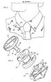
- Figure 1 shows a button down dress shirt with fabric 50 and a collar point 40.
- a grommet 20, in accordance with the invention is located on the collar point 40 at the location conventionally occupied by a button hole.
- An anchoring means 30 is attached to the shirt body at the location normally occupied by the button for the button hole.
- a unitary button and shank 10 is provided with the shank designed to pass through the grommet 20 and attach thereto with a snap action while the end of the shank is designed for releasable attachment to the anchoring means 30, when the shank is extending through the grommet 20.
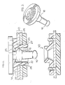
- Figure 2 shows a unitary button and shank. This may be molded from plastic or made of any other material.
- the button has an outer surface 12 which will be exposed in use and a lower surface 14 with a shank 16 extending therefrom.
- the shank 16 is provided with an enlarged free end 19 for connection to anchoring means 30 and an intermediate enlargement 18 for snap attachment to and release of the grommet 20.
- the grommet 20 comprises a hollow sleeve 22 having on one side a radially extending flange 24 designed to rest on one side of the fabric layer 40 composed here of a double layer of fabric (forming part of point 40) while the sleeve 20 goes through a hole in the fabric.
- a ring 26 fits over the free end of the sleeve 22 to rest on the other side of the fabric, and, together with the flange and sleeve, to form the assembled grommet.
- the ring may be attached to the sleeve in any desired manner. It is preferred to make both grommet members from molded, somewhat resilient, plastic.
- the annular enlargement 28 at the free end of the sleeve, bevelled at 27, is provided to assist the ring to slide thereover, compressing the adjacent sleeve, which snaps back to retain the enlargement 28 with the inwardly facing shoulder 29.
- the ring 26 may be alternately or additionally held in place by adhesive or by thermal bonding or other conventional means.
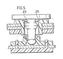
- the ring 26 fixed on the sleeve 22 attaches the grommet to material 40 and defines a passage for the button shank 10 through the inner surface of the sleeve.
- Inwardly projecting annular ledge 25 forms a restriction in the inner surface of sleeve.
- the inwardly directed edge 33 of the ledge is designed to allow, with or without deflection, inward passage of the enlargement 19 and to be deflected to pass enlargement 18 with a snap action on insertion of the shank into or removal of the shank from the grommet passage.
- the grommet and shank or one of them is made of material sufficiently resilient to achieve such snap action. Any other cooperating means on grommet passage and shank to provide such snap action and releasable retention is within the scope of the invention.
- FIG 2 shows the preferred form of the anchoring means 30 for attachment to the shirt fabric at the location normally occupied by the 'button-down' button.
- the anchoring means (preferably of molded plastic) comprises an outer member 32 attached to an inner member by four probes 36 of inner member 34 passing outwardly through the shirt material.
- the outer member is arranged to define a socket 30 (see Figures 4 and 5) designed, (with the inherent resiliency of the member) to receive with snap action, the enlarged shank end 19, and to release it with a similar snap action.
- any suitable cooperating means between the shank and the anchoring means 30 for releasable retention may be used.
- Figure 3 shows a button and shank functionally equivalent to the same members in Figure 2 except that the outer surface is jewelled instead of the button appearance of Figure 2.
- the button head is dimensioned to overlie and conceal the grommet in use.
- the dress shirt when purchased will normally have the grommet 20 and the anchoring means 30 permanently installed.
- the buttons with shanks are selected by the wearer.
- Each shank is then inserted through a grommet until both enlargements 19 and 18 have passed the restriction 25, the enlargement 18 passing with the snap action referred to.
- each button is now fixed on the collar.
- each shank free end enlargement 19 is snapped into the anchoring means socket and the shirt collar point is thus 'buttoned down'.
- the wearer now wants to replace the conventional 'button' appearance of the Figure 1 button he withdraws the shank first from the anchoring means, then outwardly through the grommet.
- a differently ornamented button and shank is selected such as the jewelled one of Figure 3, and inserted as previously described.
Landscapes
- Details Of Garments (AREA)
- Slide Fasteners, Snap Fasteners, And Hook Fasteners (AREA)
Applications Claiming Priority (1)
| Application Number | Priority Date | Filing Date | Title |
|---|---|---|---|
| US06/939,941 US4777704A (en) | 1986-12-09 | 1986-12-09 | Button with grommet |
Publications (2)
| Publication Number | Publication Date |
|---|---|
| EP0353364A1 true EP0353364A1 (fr) | 1990-02-07 |
| EP0353364B1 EP0353364B1 (fr) | 1993-05-19 |
Family
ID=25473970
Family Applications (1)
| Application Number | Title | Priority Date | Filing Date |
|---|---|---|---|
| EP88307267A Expired - Lifetime EP0353364B1 (fr) | 1986-12-09 | 1988-08-05 | Bouton-pression |
Country Status (3)
| Country | Link |
|---|---|
| US (1) | US4777704A (fr) |
| EP (1) | EP0353364B1 (fr) |
| DE (1) | DE3881211T2 (fr) |
Cited By (1)
| Publication number | Priority date | Publication date | Assignee | Title |
|---|---|---|---|---|
| WO2004103108A1 (fr) * | 2003-05-21 | 2004-12-02 | Andrea Prym-Bruck, Prym Design | Bijou a porter sur le corps ou sur un vetement |
Families Citing this family (26)
| Publication number | Priority date | Publication date | Assignee | Title |
|---|---|---|---|---|
| US4777704A (en) * | 1986-12-09 | 1988-10-18 | Acker Charles W | Button with grommet |
| DE3928529A1 (de) * | 1989-08-29 | 1991-03-07 | Prym Werke William | Knopf, insbesondere fuer kleidungsstuecke |
| US4962573A (en) * | 1989-10-17 | 1990-10-16 | Geerpres, Inc. | Clasp for retaining containers |
| US5511919A (en) * | 1992-11-03 | 1996-04-30 | Scalise; Dane C. | Locking fastener |
| US5362187A (en) * | 1992-11-03 | 1994-11-08 | Scalise Dane C | Releasable locking fastener |
| FR2700673A1 (fr) * | 1993-01-26 | 1994-07-29 | Ruffino Gilbert | Système de bouton, notamment pour vêtement. |
| USD354720S (en) | 1993-09-30 | 1995-01-24 | Estes David R | Button |
| USD377919S (en) * | 1995-06-21 | 1997-02-11 | Lou Singer | Cuff link |
| US5758678A (en) * | 1997-05-09 | 1998-06-02 | Wu; Tsun-Zong | Stabilized umbrella top structure |
| US6510629B1 (en) * | 1997-09-12 | 2003-01-28 | The Badge Company (Proprietary) Limited | Badge and method of making it |
| DE10217285A1 (de) * | 2002-04-12 | 2003-11-06 | Coreta Gmbh | Elektromechanischer Energiewandler |
| JP4990880B2 (ja) * | 2005-03-31 | 2012-08-01 | シュワブ、フランシス | セルフロック連結装置 |
| US20080263839A1 (en) * | 2007-04-26 | 2008-10-30 | Jeffery Neil Stillwell | Elastic and resilient panel and grommet for interchangeable logos |
| US20090158562A1 (en) * | 2007-12-21 | 2009-06-25 | Hanh Contey | Removably mounted fastening components |
| US20100024479A1 (en) * | 2008-07-29 | 2010-02-04 | Yvonne Palko Corona | Fastener for securing jewelry item |
| US8522404B2 (en) * | 2009-03-19 | 2013-09-03 | Danny Matei | Button assembly |
| US20130302541A1 (en) * | 2012-05-10 | 2013-11-14 | Kathlene Lynn Morgan | Special interchangeable accessory line device and the business method for its implementation as an enterprise |
| GB2504324B (en) * | 2012-07-26 | 2015-12-16 | Marks Spencer Plc | Improvements in or relating to buttons |
| US9149669B2 (en) * | 2013-02-01 | 2015-10-06 | 3M Innovative Properties Company | Respiratory protection device harness assembly |
| US10455901B2 (en) | 2015-01-04 | 2019-10-29 | Anibal Marin | Interchangeable button system technology |
| US9599135B1 (en) * | 2016-03-17 | 2017-03-21 | Hong Kwan Kim | Fastening apparatus and method for fastening a component to a material of an accessory |
| USD842165S1 (en) * | 2016-11-26 | 2019-03-05 | Anibal Marin | Interchangeable button assembly |
| USD793903S1 (en) * | 2017-02-21 | 2017-08-08 | Capitol Industrial Design Llc | Button adapter |
| IT201700033428A1 (it) * | 2017-03-27 | 2018-09-27 | A M F S P A | Kit per la personalizzazione di prodotti ed accessori di abbigliamento e pelletteria. |
| USD1040686S1 (en) * | 2017-06-28 | 2024-09-03 | David Puglia | Magnetic button |
| CN222376918U (zh) * | 2024-06-12 | 2025-01-21 | 浙江实诚塑业有限公司 | 一种用于装饰配件的固定结构 |
Citations (6)
| Publication number | Priority date | Publication date | Assignee | Title |
|---|---|---|---|---|
| DE117961C (fr) * | ||||
| US1368878A (en) * | 1920-10-20 | 1921-02-15 | Bandell Nathan | Snap ornament fastener |
| DE867465C (de) * | 1950-08-13 | 1953-02-19 | Magdalene Probst | Loesbarer Knopf fuer Kleidungsstuecke od. dgl. |
| DE2117190A1 (de) * | 1971-04-08 | 1972-10-12 | William Prym-Werke Kg, 5190 Stolberg | Druckknopfverschlußelement |
| DE3107131A1 (de) * | 1980-02-29 | 1982-01-14 | Yoshida Kogyo K.K., Tokyo | Oese |
| US4777704A (en) * | 1986-12-09 | 1988-10-18 | Acker Charles W | Button with grommet |
Family Cites Families (17)
| Publication number | Priority date | Publication date | Assignee | Title |
|---|---|---|---|---|
| US646667A (en) * | 1900-01-17 | 1900-04-03 | William H Mcdonald | Combined wristband and cuff holder. |
| GB190905447A (en) * | 1909-03-06 | 1909-11-11 | Thomas Morton | Improvements in Collar Studs. |
| US1690129A (en) * | 1928-05-07 | 1928-11-06 | Louis W Prentiss | Separable button |
| US2683908A (en) * | 1952-04-05 | 1954-07-20 | Scovill Manufacturing Co | Three-part snap fastener, including a detachable button element |
| US2748517A (en) * | 1953-09-03 | 1956-06-05 | Harriett L Berkis | Removable decorations for clothing |
| US2928151A (en) * | 1956-03-07 | 1960-03-15 | Patent Button Co | Face cap |
| US3644965A (en) * | 1968-10-16 | 1972-02-29 | Togs Inc | Snap fastener |
| US3689962A (en) * | 1970-10-19 | 1972-09-12 | Janet E Erikson | Releasable button-like element |
| US3691597A (en) * | 1971-07-27 | 1972-09-19 | Togs Inc | Two-part snap-on fastening device |
| US3967348A (en) * | 1973-08-10 | 1976-07-06 | Rogen Neil E | Button structure |
| US3996647A (en) * | 1974-06-12 | 1976-12-14 | Bengtsson Sigurd W | Button including a male and female portion |
| DE2919023A1 (de) * | 1979-05-11 | 1980-11-20 | Itw Ateco Gmbh | Druckknopf aus kunststoff |
| US4344240A (en) * | 1981-01-16 | 1982-08-17 | S And S Associates | Identification snap |
| JPS6483Y2 (fr) * | 1981-03-13 | 1989-01-05 | ||
| US4516294A (en) * | 1982-03-10 | 1985-05-14 | Dilworth Sanderson | Self locking holder for an item of jewelry |
| JPS5921207U (ja) * | 1982-08-02 | 1984-02-09 | 日本ノ−シヨン工業株式会社 | かしめ型釦のかしめ金具 |
| JPS5925208U (ja) * | 1982-08-11 | 1984-02-16 | 日本ノ−シヨン工業株式会社 | 被服用釦 |
-
1986
- 1986-12-09 US US06/939,941 patent/US4777704A/en not_active Expired - Fee Related
-
1988
- 1988-08-05 DE DE88307267T patent/DE3881211T2/de not_active Expired - Fee Related
- 1988-08-05 EP EP88307267A patent/EP0353364B1/fr not_active Expired - Lifetime
Patent Citations (6)
| Publication number | Priority date | Publication date | Assignee | Title |
|---|---|---|---|---|
| DE117961C (fr) * | ||||
| US1368878A (en) * | 1920-10-20 | 1921-02-15 | Bandell Nathan | Snap ornament fastener |
| DE867465C (de) * | 1950-08-13 | 1953-02-19 | Magdalene Probst | Loesbarer Knopf fuer Kleidungsstuecke od. dgl. |
| DE2117190A1 (de) * | 1971-04-08 | 1972-10-12 | William Prym-Werke Kg, 5190 Stolberg | Druckknopfverschlußelement |
| DE3107131A1 (de) * | 1980-02-29 | 1982-01-14 | Yoshida Kogyo K.K., Tokyo | Oese |
| US4777704A (en) * | 1986-12-09 | 1988-10-18 | Acker Charles W | Button with grommet |
Cited By (1)
| Publication number | Priority date | Publication date | Assignee | Title |
|---|---|---|---|---|
| WO2004103108A1 (fr) * | 2003-05-21 | 2004-12-02 | Andrea Prym-Bruck, Prym Design | Bijou a porter sur le corps ou sur un vetement |
Also Published As
| Publication number | Publication date |
|---|---|
| DE3881211T2 (de) | 1994-01-05 |
| US4777704A (en) | 1988-10-18 |
| EP0353364B1 (fr) | 1993-05-19 |
| DE3881211D1 (de) | 1993-06-24 |
Similar Documents
| Publication | Publication Date | Title |
|---|---|---|
| EP0353364B1 (fr) | Bouton-pression | |
| US4959890A (en) | Interchangeable snap button system | |
| US6568044B1 (en) | Attachment device for pliant material | |
| US4554710A (en) | Tie tack | |
| US6865751B1 (en) | Method and apparatus for temporarily and decoratively altering clothing | |
| KR100332855B1 (ko) | 고정구를 구비한 넥타이 | |
| US5035000A (en) | Shirt cuff watch | |
| US4043006A (en) | Button locking device | |
| US20060236509A1 (en) | Magnetically Clasping Clothing Fastener for Presenting an Adornment | |
| CN104507339A (zh) | 以包括背带功能的方式制作的上衣 | |
| US3010169A (en) | Garment detachable snap fasteners | |
| US1068976A (en) | Wearing-apparel. | |
| US4052771A (en) | Cuff linking device | |
| CA1309231C (fr) | Bouton a oeillet | |
| USRE30701E (en) | Button locking device | |
| US6550109B2 (en) | Button latch | |
| JP3427048B2 (ja) | ボタン穴及びこれを用いた各種物品 | |
| US3097362A (en) | Simulated four-in-hand tie construction | |
| US20210106100A1 (en) | Cuff Loop Fastening Devices and Methods of Using | |
| EP1157624A1 (fr) | Bouton-poussoir | |
| JPH0755928Y2 (ja) | カフスボタン | |
| JPH0268003A (ja) | 織地を結合するホツク | |
| US2882530A (en) | Spike-grip for interchangeable fur collars | |
| KR102708799B1 (ko) | 탈부착 장치 및 이를 포함하는 패션 소품 | |
| JP2005189647A (ja) | 服飾用係止具 |
Legal Events
| Date | Code | Title | Description |
|---|---|---|---|
| PUAI | Public reference made under article 153(3) epc to a published international application that has entered the european phase |
Free format text: ORIGINAL CODE: 0009012 |
|
| AK | Designated contracting states |
Kind code of ref document: A1 Designated state(s): DE FR GB IT |
|
| 17P | Request for examination filed |
Effective date: 19900608 |
|
| 17Q | First examination report despatched |
Effective date: 19911206 |
|
| GRAA | (expected) grant |
Free format text: ORIGINAL CODE: 0009210 |
|
| AK | Designated contracting states |
Kind code of ref document: B1 Designated state(s): DE FR GB IT |
|
| REF | Corresponds to: |
Ref document number: 3881211 Country of ref document: DE Date of ref document: 19930624 |
|
| ITF | It: translation for a ep patent filed | ||
| ITF | It: translation for a ep patent filed | ||
| ET | Fr: translation filed | ||
| PLBE | No opposition filed within time limit |
Free format text: ORIGINAL CODE: 0009261 |
|
| STAA | Information on the status of an ep patent application or granted ep patent |
Free format text: STATUS: NO OPPOSITION FILED WITHIN TIME LIMIT |
|
| 26N | No opposition filed | ||
| PGFP | Annual fee paid to national office [announced via postgrant information from national office to epo] |
Ref country code: GB Payment date: 19970728 Year of fee payment: 10 |
|
| PGFP | Annual fee paid to national office [announced via postgrant information from national office to epo] |
Ref country code: FR Payment date: 19970811 Year of fee payment: 10 Ref country code: DE Payment date: 19970811 Year of fee payment: 10 |
|
| PG25 | Lapsed in a contracting state [announced via postgrant information from national office to epo] |
Ref country code: GB Free format text: LAPSE BECAUSE OF NON-PAYMENT OF DUE FEES Effective date: 19980805 |
|
| GBPC | Gb: european patent ceased through non-payment of renewal fee |
Effective date: 19980805 |
|
| PG25 | Lapsed in a contracting state [announced via postgrant information from national office to epo] |
Ref country code: FR Free format text: LAPSE BECAUSE OF NON-PAYMENT OF DUE FEES Effective date: 19990430 |
|
| PG25 | Lapsed in a contracting state [announced via postgrant information from national office to epo] |
Ref country code: DE Free format text: LAPSE BECAUSE OF NON-PAYMENT OF DUE FEES Effective date: 19990601 |
|
| REG | Reference to a national code |
Ref country code: FR Ref legal event code: ST |
|
| PG25 | Lapsed in a contracting state [announced via postgrant information from national office to epo] |
Ref country code: IT Free format text: LAPSE BECAUSE OF NON-PAYMENT OF DUE FEES;WARNING: LAPSES OF ITALIAN PATENTS WITH EFFECTIVE DATE BEFORE 2007 MAY HAVE OCCURRED AT ANY TIME BEFORE 2007. THE CORRECT EFFECTIVE DATE MAY BE DIFFERENT FROM THE ONE RECORDED. Effective date: 20050805 |