EP0353444A2 - Mécanisme d'impression et sa méthode de fabrication pour imprimante à impact - Google Patents
Mécanisme d'impression et sa méthode de fabrication pour imprimante à impact Download PDFInfo
- Publication number
- EP0353444A2 EP0353444A2 EP89111348A EP89111348A EP0353444A2 EP 0353444 A2 EP0353444 A2 EP 0353444A2 EP 89111348 A EP89111348 A EP 89111348A EP 89111348 A EP89111348 A EP 89111348A EP 0353444 A2 EP0353444 A2 EP 0353444A2
- Authority
- EP
- European Patent Office
- Prior art keywords
- electromagnets
- movement
- sliders
- adjustive
- longitudinal
- Prior art date
- Legal status (The legal status is an assumption and is not a legal conclusion. Google has not performed a legal analysis and makes no representation as to the accuracy of the status listed.)
- Ceased
Links
- 230000007246 mechanism Effects 0.000 title claims abstract description 32
- 238000000034 method Methods 0.000 title claims description 10
- 238000004519 manufacturing process Methods 0.000 title claims description 7
- 230000000570 adjustive effect Effects 0.000 claims abstract description 36
- 230000009021 linear effect Effects 0.000 claims description 8
- 238000012544 monitoring process Methods 0.000 claims description 2
- 230000001105 regulatory effect Effects 0.000 claims 1
- 230000000694 effects Effects 0.000 abstract description 3
- 230000000712 assembly Effects 0.000 abstract description 2
- 238000000429 assembly Methods 0.000 abstract description 2
- 238000003466 welding Methods 0.000 abstract description 2
- 238000004873 anchoring Methods 0.000 abstract 1
- 238000005457 optimization Methods 0.000 description 3
- 229910001369 Brass Inorganic materials 0.000 description 2
- 239000010951 brass Substances 0.000 description 2
- 238000003754 machining Methods 0.000 description 2
- 229910000976 Electrical steel Inorganic materials 0.000 description 1
- NRTOMJZYCJJWKI-UHFFFAOYSA-N Titanium nitride Chemical compound [Ti]#N NRTOMJZYCJJWKI-UHFFFAOYSA-N 0.000 description 1
- 230000001419 dependent effect Effects 0.000 description 1
- 230000001627 detrimental effect Effects 0.000 description 1
- 238000005538 encapsulation Methods 0.000 description 1
- 230000004907 flux Effects 0.000 description 1
- 238000003475 lamination Methods 0.000 description 1
- 238000012423 maintenance Methods 0.000 description 1
- 239000000463 material Substances 0.000 description 1
- 230000013011 mating Effects 0.000 description 1
- 239000002184 metal Substances 0.000 description 1
- 229910052751 metal Inorganic materials 0.000 description 1
- 239000013528 metallic particle Substances 0.000 description 1
- 239000002991 molded plastic Substances 0.000 description 1
- 239000004033 plastic Substances 0.000 description 1
- 239000012255 powdered metal Substances 0.000 description 1
- 125000006850 spacer group Chemical group 0.000 description 1
- 229910001220 stainless steel Inorganic materials 0.000 description 1
- 239000010935 stainless steel Substances 0.000 description 1
Images


Classifications
-
- B—PERFORMING OPERATIONS; TRANSPORTING
- B41—PRINTING; LINING MACHINES; TYPEWRITERS; STAMPS
- B41J—TYPEWRITERS; SELECTIVE PRINTING MECHANISMS, i.e. MECHANISMS PRINTING OTHERWISE THAN FROM A FORME; CORRECTION OF TYPOGRAPHICAL ERRORS
- B41J9/00—Hammer-impression mechanisms
- B41J9/02—Hammers; Arrangements thereof
- B41J9/10—Hammers; Arrangements thereof of more than one hammer, e.g. one for each character position
-
- B—PERFORMING OPERATIONS; TRANSPORTING
- B41—PRINTING; LINING MACHINES; TYPEWRITERS; STAMPS
- B41J—TYPEWRITERS; SELECTIVE PRINTING MECHANISMS, i.e. MECHANISMS PRINTING OTHERWISE THAN FROM A FORME; CORRECTION OF TYPOGRAPHICAL ERRORS
- B41J9/00—Hammer-impression mechanisms
- B41J9/02—Hammers; Arrangements thereof
- B41J9/127—Mounting of hammers
-
- B—PERFORMING OPERATIONS; TRANSPORTING
- B41—PRINTING; LINING MACHINES; TYPEWRITERS; STAMPS
- B41J—TYPEWRITERS; SELECTIVE PRINTING MECHANISMS, i.e. MECHANISMS PRINTING OTHERWISE THAN FROM A FORME; CORRECTION OF TYPOGRAPHICAL ERRORS
- B41J9/00—Hammer-impression mechanisms
- B41J9/26—Means for operating hammers to effect impression
- B41J9/38—Electromagnetic means
Definitions
- This invention relates to print mechanisms, of the linear actuater type, that have laterally spaced and longitudinally movable ram or slider members which are selectively driven forwardly by electromagnets and are returned rearwardly by spring-damper units.
- Each slider member of a printing mechanism of the foregoing type customarily has a hammer face at its forward end, a bumper surface at its rearward end, and armature elements intermediate its length.
- the hammer face engages a print band or the like during each electromagnetically-induced stroke of forward movement of the slider, and the bumper surface engages a damper pad of the associated spring-damper unit upon spring-induced return movement of the slider in a rearward direction to an inactive position.
- the hammer faces of the sliders should be in substantial lateral alignment when the sliders occupy their inactive positions, and each forward stroke of slider movement should be of minimum duration or "flight time" and should generate an impact force of maximum magnitude between the hammer face of the slider and the print band.
- the flight time and impact force attendant each forward stroke of slider movement are affected by and dependent in significant part upon the relative longitudinal positional relationship present between the pole faces of the electromagnets and the armature elements of the slider when the slider occupies its inactive position.
- the inactive position occupied by the slider is determined by the location of the damper pad of the spring-damper unit associated with the slider, and may be varied in a longitudinal direction by adjustment of the unit when it is capable of adjustive movement in such direction.
- Positional adjustment of the spring-damper units may be employed either to laterally align the hammer faces of the sliders or to optimize their strokes of forward movement, but not for both purposes. Adjustment of the units for the former purpose does not also result in optimization of the forward strokes of slider movement, and adjustment of the units for the later purpose leaves the hammer faces of the sliders laterally nonaligned.
- One previously proposed way of correcting misalignment of the hammer faces has been by subjecting them to a grinding operation after positional adjustment of the spring-damper units has been completed. This method of effecting lateral alignment between the hammer faces is time-consuming and costly, and additionally risks introduction into the print mechanism of metallic particles detrimental to its operation.
- Print mechanisms of the linear actuator type that have slider or ram members which are driven forwardly by associated electromagnets, and which are returned rearwardly by spring-containing units, are disclosed in the IBM Technical Disclosure Bulletin entitled HORIZONTAL SLIDING PRINT MECHANISM (Vol. 25, No. 11B, April 1983), and in the following United States Patents: 4,371,857, 4,388,861, 4,412,197, 4,425,845 and 4,527,139.
- Patent 4,388,861 also refers in its "Background Art” section to a printer, of the "clapper” type instead of the linear actuator type, in which adjustment of flight time is realized by adjustment of electromagnets associated with the print hammer units.
- the present invention provides an improved linear-action printing mechanism and manufacturing method that permit economical mass production of the mechanisms, optimization of the flight times and impact forces attendant forward movement of their slider components, and efficient lateral alignment of the hammer faces of the sliders.
- the print mechanism of the invention has spring-damper units and electromagnet actuators that are independently adjustable in the longitudinal direction, i.e., direction parallel to the longitudinal axes of the sliders with which they are are associated.
- each spring-damper unit is longitudinally adjusted as required to bring the forward ends of the sliders into substantial lateral alignment with each other.
- the longitudinal positions of the electromagnets are then adjusted as necessary to optimize the flight time and impact force attendant forward movement of the sliders. Since post-assembly grinding or similar machining of the sliders is not required, the mechanisms can be economically produced.
- an inexpensive stamped frame plate in lieu of more expensive machined or similarly formed components, for separating the sliders from each other and constraining their lateral movement.
- Such plate may and preferably does also establish and maintain desired spacings between pole faces of confronting ones of the electromagnets, and provides smooth surfaces upon which adjustive sliding movement of the electromagnets can readily occur.
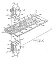
- Module 10 designates one of a plurality of modules, the remainder of which are not shown, of a high-speed impact printer of the linear actuator type.
- Module 10 has frame means consisting of relatively massive upper and lower frame members 12, 12′, preferably formed of nonmagnetic stainless steel powdered metal, and a relatively thin frame plate 14 that preferably is formed from brass and by a stamping operation.
- Plate 14 is positioned between frame members 12, 12′, spaces them from each other, and has its forward end an upturned edge 16 that is received within a downwardly-opening groove 18 provided within the forward portion of upper frame member 12.
- the foregoing frame components are secured together by pin and screw-type fasteners 20, 22, 23 of which only illustrative ones are shown in Fig. 1.
- Frame plate 14 has a plurality (illustratively eight) of laterally spaced parallel slots 24 which extend forwardly from the rear edge of plate 14 and pass under its upturned forward edge 16. Slots 24 receive and constrain lateral movement of respective ones of a corresponding plurality of elongate ram or slider members 26, 26′, of which only illustrative ones are shown. As is best shown in Fig. 5, each slider 26 has an elongate lightweight body 28 that preferably is formed of injection-molded plastic material and that has an impact surface 29 at its rear end.
- the slider body supports at its forward end a hammer face 30, preferably formed of stamped sheet metal, and has intermediate its length a plurality (illustratively four) of armature elements 32 preferably formed of chemically etched electrical steel coated with titanium nitride. Openings are also provided through slider body 28, for the purpose of further reducing its weight and/or of receiving fastener and other components of module 10. Sliders 26′, which alternate with sliders 26 in a lateral direction, differ from them only in that their armature elements and certain of their openings are disposed at different locations along their length.
- Spring-damper means in the form of units 34 are associated with respective ones of the sliders 26, 26′.
- Each unit 34 has upper body portions 36, 38 that overlie the upper surface of upper frame member 12.
- Each unit 34 also has a downwardly depending body portion 40 and a downwardly depending U-shaped spring element 42 which extend through vertically aligned openings 44 of frame members 12, 12′.
- the spring element 42 of each unit 34 also extends through an elongate opening 46 within the associated one of the sliders 26 or 26′, and the rearward leg of the spring element resiliently biases such slider to a rearward inactive position wherein the bumper surface 29 of the slider engages a multi-layered rubber damper pad 48 secured to the forward face of downwardly depending portion 40 of unit 34.
- each unit 34 are significantly less than those of the openings 44 through which it extends, in the longitudinal direction (i.e., parallel to the central axes of slider elements 26, 26′ and the frame plate slots 24 within which such sliders are received).
- An opening 50 within the upper rearward portion 38 of each unit 34 similarly has a dimension in the longitudinal direction that is significantly greater than the diameter of a screw-type fastener 52 that extends through opening 50, an aligned opening of a gang washer 53 overlying body portion 38 of unit 34, and into a mating threaded bore 39 within upper frame member 12.
- the foregoing dimensional relationships permit longitudinal adjustment of the position of each spring-damper unit 34, and thus of the longitudinal inactive position of the slider 26 or 26′ associated therewith. Following positional adjustment of units 34 they are secured in place by tightening fasteners 52.
- This preferably and illustratively consists of pairs of electromagnets 54 that are associated with respective ones of the sliders 26 or 26′.
- the electromagnets 54 of each pair are disposed in vertical alignment with each other upon opposite sides of the associated slider, and project through an aligned pair of the openings 56 extending through upper and lower frame members 12, 12′.
- the openings 56 of each frame member are preferably and illustratively staggered in a lateral direction so as to permit more components to be "packed" into a print mechanism of given size.
- Each electromagnet 54 includes a plurality of stamped laminations that are welded together to form a stator core 58, and a bobbin-wound coil 60 that is secured thereto by plastic encapsulation. Coil 60 is energized at desired times via electrical contacts 61 projecting from the outer end of each electromagnet. At its inner end, each electromagnet has four pole faces 62 which are adapted to be in substantial vertical alignment with the armature elements 32 of the associated slider 26 or 26′ at those times when the magnetic flux generated by electromagnets 54, upon energization thereof, has advanced the slider forwardly from its inactive position to its active "print" position.
- the rearward edges of the pole faces 62 of the associated electromagnets 54 are in approximate vertical alignment with the forward edges of the slider armature elements 32.
- feet 64 are provided at the four corners of stator core 58. The feet engage those sections of brass frame plate 14 upon opposite sides of the frame plate opening or slot 24 within which the associated slider 26 or 26′ is mounted. Such engagement ensures realization and maintenance of proper vertical spacing between the pole faces 62 of the electromagnets 54 of each vertically aligned pair.
- the electromagnet-receiving openings 56 within frame members 12, 12′ therefore need not be and preferably are not so constructed as to maintain such spacing between electromagnets 54.
- the relative dimensions of electromagnets 54 and of the frame openings 56 within which they are received are such as to permit longitudinal adjustive movement of the electromagnets relative to frame members 12, 12′, and thus relative to the sliders 26 or 26′ with which electromagnets 54 are associated. Since relative longitudinal adjustive movement between each electromagnet 54 and its associated slider 26 or 26′ is realized by adjustive longitudinal movement of the electromagnet, the forward stroke of movement undergone by each slider can be optimized, from the viewpoint of flight time and impact force, without disturbing lateral alignment previously produced between the forward ends of the sliders by longitudinal adjustment of the positions of spring-damper assemblies 34.
- Each gang clamp/retainer plate pair is secured to its associated frame member 12 or 12′ by screw-type fasteners 68, only two of which are shown in Fig. 1. These extend through bores of the retainer plate and clamp, and through tubular spacer studs 70, and then into threaded bores of frame member 12 or 12′.
- the method of manufacturing a print mechanism of the type in question preferably includes the steps of assembling the frame components 12, 12′, 14 and the sliders 26, 26′ with each other, mounting the electromagnets 54 and the spring-damper units 34 upon the frame means for independent adjustive longitudinal movement relative to the frame means and to each other, adjusting the longitudinal positions of spring-damper units 34 to effect substantial lateral alignment of the forward ends of sliders 26, 26′, securing spring-damper units 34 in their adjustive positions, adjusting the longitudinal positions of electromagnets 54 to vary the characteristics of the forward strokes of movements imparted by them to sliders 26, 26′, and fixedly securing electromagnets 54 to the frame means in those adjustive positions wherein optimal slider movement is realized.
- the step of mounting electromagnets 54 for adjustive movement preferably further includes subjecting them to clamping forces that permit their movement between different adjustive positions, but which are sufficient to temporarily maintain the electromagnets stationary when adjustive forces are not being applied to them.
- the method preferably further includes monitoring the movement characteristics imparted to each slider 26 or 26′ by its associated electromagnets 54 in different adjustive positions of the electromagnets, for the purpose of identifying the adjustive position wherein optimal movement characteristics of the slider are realized.
- the print mechanism of the present invention permits independent adjustment of the sliders' lateral alignment and of their forward strokes of movement, both adjustments may be precisely made and post-assembly grinding or other machining of the forward slider ends is not necessary. This contributes significantly to the ease and economy of manufacture of the print mechanism. Also significant in the foregoing regard is the utilization in the mechanism of an inexpensive stamped frame plate that performs the multiple functions of restricting lateral movement of the sliders, maintaining optimal spacing between the pole faces of confronting ones of the electromagnets, and providing a surface upon which adjustive movement of the electromagnets can readily occur.
Landscapes
- Physics & Mathematics (AREA)
- Electromagnetism (AREA)
- Impact Printers (AREA)
Applications Claiming Priority (2)
| Application Number | Priority Date | Filing Date | Title |
|---|---|---|---|
| US229033 | 1988-08-05 | ||
| US07/229,033 US4867059A (en) | 1988-08-05 | 1988-08-05 | Impact printer print mechanism and method of manufacture |
Publications (2)
| Publication Number | Publication Date |
|---|---|
| EP0353444A2 true EP0353444A2 (fr) | 1990-02-07 |
| EP0353444A3 EP0353444A3 (fr) | 1990-07-04 |
Family
ID=22859568
Family Applications (1)
| Application Number | Title | Priority Date | Filing Date |
|---|---|---|---|
| EP89111348A Ceased EP0353444A3 (fr) | 1988-08-05 | 1989-06-22 | Mécanisme d'impression et sa méthode de fabrication pour imprimante à impact |
Country Status (3)
| Country | Link |
|---|---|
| US (1) | US4867059A (fr) |
| EP (1) | EP0353444A3 (fr) |
| JP (1) | JPH0692173B2 (fr) |
Families Citing this family (7)
| Publication number | Priority date | Publication date | Assignee | Title |
|---|---|---|---|---|
| DE102011112274A1 (de) | 2011-09-05 | 2013-03-07 | Brose Fahrzeugteile Gmbh & Co. Kg, Hallstadt | Steuersystem |
| DE102011121775B3 (de) | 2011-12-21 | 2013-01-31 | Brose Fahrzeugteile Gmbh & Co. Kg, Hallstadt | Steuersystem |
| DE102012013065A1 (de) | 2012-07-02 | 2014-01-02 | Brose Fahrzeugteile Gmbh & Co. Kg, Hallstadt | Verfahren zur Ansteuerung einer Verschlusselementanordnung eines Kraftfahrzeugs |
| DE102013114883A1 (de) | 2013-12-25 | 2015-06-25 | Brose Fahrzeugteile Gmbh & Co. Kommanditgesellschaft, Hallstadt | Steuersystem für eine motorische Verschlusselementanordnung eines Kraftfahrzeugs |
| DE102013114881A1 (de) | 2013-12-25 | 2015-06-25 | Brose Fahrzeugteile Gmbh & Co. Kommanditgesellschaft, Hallstadt | Steuersystem für eine motorische Verschlusselementanordnung eines Kraftfahrzeugs |
| DE102015112589A1 (de) | 2015-07-31 | 2017-02-02 | Brose Fahrzeugteile Gmbh & Co. Kommanditgesellschaft, Bamberg | Steuersystem für eine motorisch verstellbare Laderaumvorrichtung eines Kraftfahrzeugs |
| DE102015119701A1 (de) | 2015-11-15 | 2017-05-18 | Brose Fahrzeugteile Gmbh & Co. Kommanditgesellschaft, Bamberg | Verfahren für den Betrieb einer kapazitiven Sensoranordnung eines Kraftfahrzeugs |
Family Cites Families (9)
| Publication number | Priority date | Publication date | Assignee | Title |
|---|---|---|---|---|
| US3714892A (en) * | 1970-10-20 | 1973-02-06 | Odec Computer Syst Inc | Impact hammer for liner printer |
| US3726213A (en) * | 1970-12-07 | 1973-04-10 | Singer Co | Print hammer with high repetition rate |
| DE3018407A1 (de) * | 1980-05-14 | 1981-11-19 | Ibm Deutschland Gmbh, 7000 Stuttgart | Elektromagnetisch betaetigbarer stoesselantrieb, insbesondere fuer anschlagdrucker |
| EP0048290B1 (fr) * | 1980-09-19 | 1984-05-16 | Ibm Deutschland Gmbh | Embase pour la réception de plusieurs éléments d'impression |
| DE3114835A1 (de) * | 1981-04-11 | 1982-11-04 | Ibm Deutschland Gmbh, 7000 Stuttgart | Bank zur aufnahme mehrerer druckstoesseleinheiten |
| DE3114834A1 (de) * | 1981-04-11 | 1982-11-04 | Ibm Deutschland Gmbh, 7000 Stuttgart | Elektromagnetischer stoesselantrieb |
| US4496253A (en) * | 1983-04-20 | 1985-01-29 | Daisy Systems, Holland B.V. | Impact hammer |
| EP0127692B1 (fr) * | 1983-06-01 | 1988-06-01 | Ibm Deutschland Gmbh | Elément d'actionnement électromagnétique |
| US4768892A (en) * | 1985-07-29 | 1988-09-06 | International Business Machines Corporation | Electromagnetic hammer actuator for impact printer |
-
1988
- 1988-08-05 US US07/229,033 patent/US4867059A/en not_active Expired - Fee Related
-
1989
- 1989-06-19 JP JP1154816A patent/JPH0692173B2/ja not_active Expired - Lifetime
- 1989-06-22 EP EP89111348A patent/EP0353444A3/fr not_active Ceased
Also Published As
| Publication number | Publication date |
|---|---|
| EP0353444A3 (fr) | 1990-07-04 |
| US4867059A (en) | 1989-09-19 |
| JPH0692173B2 (ja) | 1994-11-16 |
| JPH0255168A (ja) | 1990-02-23 |
Similar Documents
| Publication | Publication Date | Title |
|---|---|---|
| US4225250A (en) | Segmented-ring magnet print head | |
| CA1108471A (fr) | Tete libre pour imprimantes par points et appareils semblables | |
| JPS6213804Y2 (fr) | ||
| US4214836A (en) | Impact print head | |
| US4867059A (en) | Impact printer print mechanism and method of manufacture | |
| EP0293638B1 (fr) | Tête d'impression à aiguilles avec électro-aimants à armature battante | |
| DE19808492A1 (de) | Elektromagnetischer Aktuator mit wirbelstromarmen Anker | |
| US4423675A (en) | Magnetic circuit and print hammer | |
| EP0072953A2 (fr) | Tête d'impression pour imprimante par points à aiguilles | |
| EP0081809B1 (fr) | Imprimante à aiguilles à construction aisée et sa méthode de fabrication | |
| EP0191549B1 (fr) | Tête d'impression par points utilisant des fils | |
| EP0022480B1 (fr) | Mécanisme d'actionnement électromagnétique pour marteaux d'impression | |
| US4708501A (en) | Electromagnetic hammer printing device including a limited action spring force | |
| JPH0414070B2 (fr) | ||
| WO1985000321A1 (fr) | Rangee de marteaux d'impression | |
| EP0210636B1 (fr) | Ensemble d'actuateurs électromagnétiques pour les marteaux d'imprimantes à impact | |
| WO1983003387A1 (fr) | Dispositif d'actionnement de tiges d'impression et son procede de fabrication | |
| EP0052202A1 (fr) | Commande pour un marteau imprimant | |
| JPH037163Y2 (fr) | ||
| CA1086132A (fr) | Appareil a imprimer a grande vitesse | |
| US5150976A (en) | Matrix printing head with forward and return articulated-armature magnets | |
| EP0408316B1 (fr) | Tête de points à impact pour une imprimante | |
| JPH06206323A (ja) | 印字ヘッド装置 | |
| KR20260008126A (ko) | 반도체 장치의 제조 장치 | |
| EP0401881B1 (fr) | Tête d'impression à aiguilles avec électro-aimants d'actionnement et de retour à armature battante |
Legal Events
| Date | Code | Title | Description |
|---|---|---|---|
| PUAI | Public reference made under article 153(3) epc to a published international application that has entered the european phase |
Free format text: ORIGINAL CODE: 0009012 |
|
| AK | Designated contracting states |
Kind code of ref document: A2 Designated state(s): DE FR GB |
|
| PUAL | Search report despatched |
Free format text: ORIGINAL CODE: 0009013 |
|
| AK | Designated contracting states |
Kind code of ref document: A3 Designated state(s): DE FR GB |
|
| 17P | Request for examination filed |
Effective date: 19900621 |
|
| 17Q | First examination report despatched |
Effective date: 19920413 |
|
| STAA | Information on the status of an ep patent application or granted ep patent |
Free format text: STATUS: THE APPLICATION HAS BEEN REFUSED |
|
| 18R | Application refused |
Effective date: 19921010 |