EP0353498A2 - Diaphragmaaufbau eines Verdichters - Google Patents
Diaphragmaaufbau eines Verdichters Download PDFInfo
- Publication number
- EP0353498A2 EP0353498A2 EP89112680A EP89112680A EP0353498A2 EP 0353498 A2 EP0353498 A2 EP 0353498A2 EP 89112680 A EP89112680 A EP 89112680A EP 89112680 A EP89112680 A EP 89112680A EP 0353498 A2 EP0353498 A2 EP 0353498A2
- Authority
- EP
- European Patent Office
- Prior art keywords
- assembly
- outer ring
- combustion turbine
- casing
- vane
- Prior art date
- Legal status (The legal status is an assumption and is not a legal conclusion. Google has not performed a legal analysis and makes no representation as to the accuracy of the status listed.)
- Withdrawn
Links
Images


Classifications
-
- F—MECHANICAL ENGINEERING; LIGHTING; HEATING; WEAPONS; BLASTING
- F02—COMBUSTION ENGINES; HOT-GAS OR COMBUSTION-PRODUCT ENGINE PLANTS
- F02C—GAS-TURBINE PLANTS; AIR INTAKES FOR JET-PROPULSION PLANTS; CONTROLLING FUEL SUPPLY IN AIR-BREATHING JET-PROPULSION PLANTS
- F02C3/00—Gas-turbine plants characterised by the use of combustion products as the working fluid
- F02C3/04—Gas-turbine plants characterised by the use of combustion products as the working fluid having a turbine driving a compressor
-
- F—MECHANICAL ENGINEERING; LIGHTING; HEATING; WEAPONS; BLASTING
- F01—MACHINES OR ENGINES IN GENERAL; ENGINE PLANTS IN GENERAL; STEAM ENGINES
- F01D—NON-POSITIVE DISPLACEMENT MACHINES OR ENGINES, e.g. STEAM TURBINES
- F01D9/00—Stators
- F01D9/02—Nozzles; Nozzle boxes; Stator blades; Guide conduits, e.g. individual nozzles
- F01D9/04—Nozzles; Nozzle boxes; Stator blades; Guide conduits, e.g. individual nozzles forming ring or sector
- F01D9/042—Nozzles; Nozzle boxes; Stator blades; Guide conduits, e.g. individual nozzles forming ring or sector fixing blades to stators
-
- F—MECHANICAL ENGINEERING; LIGHTING; HEATING; WEAPONS; BLASTING
- F04—POSITIVE - DISPLACEMENT MACHINES FOR LIQUIDS; PUMPS FOR LIQUIDS OR ELASTIC FLUIDS
- F04D—NON-POSITIVE-DISPLACEMENT PUMPS
- F04D29/00—Details, component parts, or accessories
- F04D29/40—Casings; Connections of working fluid
- F04D29/52—Casings; Connections of working fluid for axial pumps
- F04D29/54—Fluid-guiding means, e.g. diffusers
- F04D29/541—Specially adapted for elastic fluid pumps
- F04D29/542—Bladed diffusers
-
- F—MECHANICAL ENGINEERING; LIGHTING; HEATING; WEAPONS; BLASTING
- F04—POSITIVE - DISPLACEMENT MACHINES FOR LIQUIDS; PUMPS FOR LIQUIDS OR ELASTIC FLUIDS
- F04D—NON-POSITIVE-DISPLACEMENT PUMPS
- F04D29/00—Details, component parts, or accessories
- F04D29/40—Casings; Connections of working fluid
- F04D29/52—Casings; Connections of working fluid for axial pumps
- F04D29/54—Fluid-guiding means, e.g. diffusers
- F04D29/541—Specially adapted for elastic fluid pumps
- F04D29/542—Bladed diffusers
- F04D29/544—Blade shapes
Definitions
- This invention relates generally to combustion or gas turbines, and more particularly to the compressor diaphragm assemblies that are typically used in such turbines.
- combustion turbines which are also sometimes referred to as "gas turbines" are in electric-generating use. Since they are well suited for automation and remote control, combustion turbines are primarily used by electric utility companies for peak-load duty. Where additional capacity is needed quickly, where refined fuel is available at low cost, or where the turbine exhaust energy can be utilized, however, combustion turbines are also used for base-load electric generation.
- a typical combustion turbine is comprised generally of four basic portions: (1) an inlet portion; (2) a compressor portion; (3) a combustor portion; and (4) an exhaust portion. Air entering the combustion turbine at its inlet portion is compressed adiabatically in the compressor portion, and is mixed with a fuel and heated at a constant pressure in the combustor portion, thereafter being discharged through the exhaust portion with a resulting adiabatic expansion of the gases completing the basic combustion turbine cycle which is generally referred to as the Brayton, or Joule, cycle.
- a significant problem of fatigue cracking in the airfoil portion of inner-shrouded vanes exists, however, due to conventionally used methods of manufacturing such vanes.
- a welding process is used to join the vane airfoils to their respective inner and outer shrouds, such process resulting in a "heat-affected zone" at each weld joint.
- Crack initiation due to fatigue it has been found, more often than not occurs at such heat-affected zones. Therefore, it would be desirable not only to provide an improved compressor diaphragm assembly that would be resistant to fatigue cracking, but also to provide a method of fabricating such assemblies that would minimize processes which produce heat-affected zones.
- the outer shroud segment of this hypothetical vane airfoil would not be stably engaged with the casing of the combustion turbine until such time that a restraining moment could be generated by contact of the extremities of the outer shroud segment with the walls of the slot formed in the casing to receive the segment.
- the outer shroud segment would, thus, rotate within the clearance gap (provided in the casing slot to account for thermal expansion).
- use of the hypothetical vane airfoil in a combustion turbine would lead to a great deal of stress in the vicinity of the outer shroud segment and excessive translational and rotational displacements, each of which would be further exacerbated under dynamic stimuli.
- a combustion turbine comprising a casing, a rotor including a plurality of rotating blades which are axially disposed along a shaft having a plurality of discs, and one or more slots of a first predetermined cross-section formed circumferentially within the casing at a compressor portion of the turbine, said compressor portion having a diaphragm assembly with a plurality of vane airfoils each of which has an inner shroud formed integrally therewith, characterized by an outer ring sub-assembly having parallel grooves, disposed at a stagger angle, each receiving one of the plurality of vane airfoils at said stagger angle, said outer ring sub-assembly having a radially outer end portions of complementary cross-section to the first predetermined cross-section so as to be slidably received in the slots in the turbine casing, and a carrier sub-assembly for engagement with each said inner shroud,
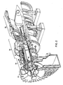
- Fig. 1 the layout of a typical electric-generating plant 10 utilizing a well known combustion turbine 12 (such as the model W-501D single shaft, heavy duty combustion turbine that is manufactured by the Combustion Turbine Systems Division of Westinghouse Electric Corporation).
- the plant 10 includes a generator 14 driven by the turbine 12, a starter package 16, an electrical package 18 having a glycol cooler 20, a mechanical package 22 having an oil cooler 24, and an air cooler 26, each of which support the operating turbine 12.
- Conventional means 28 for silencing flow noise associated with the operating turbine 12 are provided for at the inlet duct and at the exhaust stack of the plant 10, while conventional terminal means 30 are provided at the generator 14 for conducting the generated electricity therefrom.
- the turbine 12 is comprised generally of an inlet portion 32, a compressor portion 34, a combustor portion 36, and an exhaust portion 38.
- Air entering the turbine 12 at its inlet portion 32 is compressed adiabatically in the compressor portion 34, and is mixed with a fuel and heated at a constant pressure in the combustor portion 36.
- the heated fuel/air gases are thereafter discharged from the combustor portion 36 through the exhaust portion 38 with a resulting adiabatic expansion of the gases completing the basic combustion turbine cycle.
- Such thermodynamic cycle is alternatively referred to as the Brayton, or Joule, cycle.
- the compressor portion 34 is of an axial flow configuration having a rotor 40.
- the rotor 40 includes a plurality of rotating blades 42, axially disposed along a shaft 44, and a plurality of discs 46. Each adjacent pair of the plurality of rotating blades 42 is interspersed by one of a plurality of inner-shrouded stationary vanes 48, mounted to the turbine casing 50 as explained in greater detail herein below, thereby providing a diaphragm assembly in conjunction with the discs 46 with stepped labyrinth interstage seals 52.
- a "heat-affected zone” is that portion of the base metal which has not been melted, but whose mechanical properties or microstructure have been altered by the heat of welding, brazing, soldering, or cutting.
- stainless steels alloys of the type utilized for the airfoils 54, inner shrouds 56 and outer shrouds 58 crack initiation due to fatigue more often than not occurs at such heat-affected zones 60.
- Fig. 3 illustrates an inner-shrouded vane 48 that is manufactured by the rolled constant section approach
- Fig. 4 illustrates an inner-shrouded vane 48 that is manufactured by the forged variable thickness-to-chord ratio approach.
- Fatigue cracking nevertheless, would still not be eliminated through use of a hypothetical airfoil having an integrally formed inner and outer shroud, thereby doing away with the heat-affected zones 60.
- the outer shroud segment of this hypothetical vane airfoil would not be stably engaged with the casing of the combustion turbine until such time that a restraining moment could be generated by contact of the extremities of the outer shroud segment with the walls of the slot formed in the casing to receive the segment.
- the outer shroud segment would, thus, rotate within the clearance gap (provided in the casing slot to account for thermal expansion).
- use of the hypothetical vane airfoil in a combustion turbine would lead to a great deal of stress in the vicinity of the outer shroud segment and excessive translational and rotational displacement, each of which would be further exacerbated under dynamic stimuli.
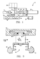
- the compressor diaphragm assembly 64 includes a plurality of vane airfoils 66, each of which is formed with an integral inner shroud 68, a segmented seal carrier 70 suspended from the inner shroud 68, and a segmented outer ring 72 for supporting the plurality of vane airfoils 66, at a predetermined angle A S (Fig. 7) with respect to the longitudinal axis of the turbine 12, through engagement with a slot 74 formed circumferentially in the casing 50 of the turbine 12.
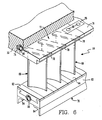
- Each of the outer ring segments 76 has one or more grooves 78 formed to engagably receive a respective one of the vane airfoils 66 at its outer portion 80.
- Each seal carrier segment 82 includes a pair of disc-engaging seals 84, and is formed to be engaged with the inner shrouds 68 of one or more vane airfoils 66.
- heat-affected zones are eliminated since the plurality of vane airfoils 66, with their integrally formed inner shrouds 68, are joined to their respective outer ring and seal carrier segments 76, 82 by processes which do not utilize heat. Furthermore, there are few if any instabilities of engagement between the vane airfoils 66 and the casing slot 74 (due either to static or dynamic stimuli) since the outer portion 80 of each vane airfoil 66 is formed to engage its respective groove 78 parallel to the predetermined angle A S .
- the predetermined angle A S is the angle at which each of the vane airfoils 66 are aligned relative to the longitudinal axis of the turbine 12. That is, and referring for the moment to Fig. 7 in conjunction with Fig. 5, the outer portion 80 of the vane airfoil 66 is rotated until it is parallel to the stagger angle, and thus, perpen dicular to the forces generated by F T . The outer portion 80 thereby engages a slot 78 formed in an outer ring segment 76 at this stagger angle A S , causing the distribution of normal forces acting on the outer portion 80 to be more uniform. This, in combination with 0.001-inch clearances typical of rotor blades, provides a stable restraint system with minimum displacements and rotations of the vane airfoils 66.
- a plurality of the vane airfoils 66 are assembled into the outer ring segments 76 by inserting their respective outer portions 80 into the grooves 78 formed in the outer ring segments 76.
- the vane airfoils 66 and especially their outer portions 80 are aligned optimally parallel to the stagger angle A S .
- each of the outer portions 80 are shown having a generally triangular shaped cross-section, it should be noted at this juncture that any such cross-section may be utilized in accordance with the present invention as long as it is complementary to the cross-section of the grooves 78.
- the respective outer ring segments 76 may be joined to form the outer ring 72 with tie bars 86 and indexing screws 88. Alternatively, the outer ring segments 76 may remain unjoined as long as the arc that is defined by the unjoined outer ring segments 76 is equal to the arc defined by the segmented seal carrier 70. In either case, the outer ring segments 76 are formed with a generally T-shaped cross-section for engagement with the slot 74 formed in the casing 50 of the turbine 12, held in place by conventional retaining screws 90.
- spacers 92 of varying sizes are provided to properly space the vane airfoils 66 one from the other.
- the inner portions 68 of each vane airfoil 66 as well as any spacers 92 between the vane airfoils 66 are locked in place as necessary with conventional retaining screws 90 or with indexing screws 88.
- the compressor diaphragm assembly according to the present invention thus eliminates problems of fatigue cracking caused by heat-affected zones. This also substantially reduces stress concentrations that typically build up at the inner and outer shrouds. Integrally formed vane airfoils minimizes costs associated with manufacture of such airfoils, while maximizing the quality of their production since long-established procedures that have been utilized for rotor blade manufacture (e.g., castings, forgings, contour millings, etc.) can be applied.
Landscapes
- Engineering & Computer Science (AREA)
- Mechanical Engineering (AREA)
- General Engineering & Computer Science (AREA)
- Physics & Mathematics (AREA)
- Geometry (AREA)
- Chemical & Material Sciences (AREA)
- Combustion & Propulsion (AREA)
- Structures Of Non-Positive Displacement Pumps (AREA)
- Turbine Rotor Nozzle Sealing (AREA)
Applications Claiming Priority (2)
| Application Number | Priority Date | Filing Date | Title |
|---|---|---|---|
| US226705 | 1981-01-21 | ||
| US07/226,705 US4889470A (en) | 1988-08-01 | 1988-08-01 | Compressor diaphragm assembly |
Publications (2)
| Publication Number | Publication Date |
|---|---|
| EP0353498A2 true EP0353498A2 (de) | 1990-02-07 |
| EP0353498A3 EP0353498A3 (de) | 1990-12-27 |
Family
ID=22850064
Family Applications (1)
| Application Number | Title | Priority Date | Filing Date |
|---|---|---|---|
| EP19890112680 Withdrawn EP0353498A3 (de) | 1988-08-01 | 1989-07-11 | Diaphragmaaufbau eines Verdichters |
Country Status (9)
| Country | Link |
|---|---|
| US (1) | US4889470A (de) |
| EP (1) | EP0353498A3 (de) |
| JP (1) | JP2835381B2 (de) |
| KR (1) | KR970001123B1 (de) |
| CN (1) | CN1040078A (de) |
| AR (1) | AR240714A1 (de) |
| AU (1) | AU613214B2 (de) |
| CA (1) | CA1333472C (de) |
| MX (1) | MX164476B (de) |
Cited By (10)
| Publication number | Priority date | Publication date | Assignee | Title |
|---|---|---|---|---|
| EP1801357A1 (de) | 2005-12-22 | 2007-06-27 | Techspace aero | Schaufelleitring einer Strömungsmaschine, Strömungsmaschine mit einem solchen Leitring und Leitschaufel |
| EP1852575A1 (de) * | 2006-01-27 | 2007-11-07 | Mitsubishi Heavy Industries, Ltd. | Stationärer Schaufelring eines Axialkompressors |
| WO2009048455A1 (en) * | 2007-01-17 | 2009-04-16 | Siemens Energy, Inc. | A gas turbine engine |
| WO2010128900A1 (en) | 2009-05-08 | 2010-11-11 | Volvo Aero Corporation | Supporting structure for a gas turbine engine |
| FR2980249A1 (fr) * | 2011-09-20 | 2013-03-22 | Snecma | Carter intermediaire structural pour une turbomachine |
| EP1967697A3 (de) * | 2007-03-07 | 2015-05-06 | General Electric Company | Turbinendüsensegment und Reparaturverfahren |
| EP2900932A4 (de) * | 2012-09-28 | 2016-07-27 | United Technologies Corp | Liner-lock-segment |
| FR3048719A1 (fr) * | 2016-03-14 | 2017-09-15 | Snecma | Redresseur de flux pour turbomachine avec plateformes integrees et rapportees |
| CN109882255A (zh) * | 2019-03-01 | 2019-06-14 | 西安航天动力研究所 | 带叶片型线槽的涡轮静子顶部封严限位结构 |
| WO2019147219A1 (en) * | 2018-01-23 | 2019-08-01 | Siemens Aktiengesellschaft | Slide on shroud cover segments for gas turbine compressor stator vanes |
Families Citing this family (32)
| Publication number | Priority date | Publication date | Assignee | Title |
|---|---|---|---|---|
| US5022818A (en) * | 1989-02-21 | 1991-06-11 | Westinghouse Electric Corp. | Compressor diaphragm assembly |
| US5236614A (en) | 1990-09-25 | 1993-08-17 | Colgate-Palmolive Company | Stable microemulsion disinfecting detergent composition |
| US5197856A (en) * | 1991-06-24 | 1993-03-30 | General Electric Company | Compressor stator |
| US5332360A (en) * | 1993-09-08 | 1994-07-26 | General Electric Company | Stator vane having reinforced braze joint |
| EP1163428B1 (de) * | 1999-03-24 | 2004-08-25 | Siemens Aktiengesellschaft | Leitschaufel und leitschaufelkranz für eine strömungsmaschine, sowie bauteil zur begrenzung eines strömungskanals |
| JP2002180803A (ja) * | 2000-12-13 | 2002-06-26 | Ishikawajima Harima Heavy Ind Co Ltd | 支持装置 |
| JP4040922B2 (ja) * | 2001-07-19 | 2008-01-30 | 株式会社東芝 | 組立式ノズルダイアフラムおよびその組立方法 |
| FR2831615B1 (fr) * | 2001-10-31 | 2004-01-02 | Snecma Moteurs | Redresseur fixe sectorise pour compresseur d'une turbomachine |
| US6644924B1 (en) * | 2002-05-31 | 2003-11-11 | General Electric Company | Covers for turbine buckets and methods of assembly |
| CN100338337C (zh) * | 2002-06-07 | 2007-09-19 | 三菱重工业株式会社 | 汽轮机转子叶片组件及其组装方法 |
| JP4590955B2 (ja) * | 2004-07-08 | 2010-12-01 | 株式会社Ihi | ステータセグメント、ステータ、及び静翼 |
| US7427187B2 (en) * | 2006-01-13 | 2008-09-23 | General Electric Company | Welded nozzle assembly for a steam turbine and methods of assembly |
| US8702385B2 (en) * | 2006-01-13 | 2014-04-22 | General Electric Company | Welded nozzle assembly for a steam turbine and assembly fixtures |
| FR2899637B1 (fr) * | 2006-04-06 | 2010-10-08 | Snecma | Aube de stator a calage variable de turbomachine |
| US20080050222A1 (en) * | 2006-08-23 | 2008-02-28 | General Electric Company | Singlet welded nozzle hybrid design for a turbine |
| US8894370B2 (en) * | 2008-04-04 | 2014-11-25 | General Electric Company | Turbine blade retention system and method |
| US8887390B2 (en) | 2008-08-15 | 2014-11-18 | Dresser-Rand Company | Method for correcting downstream deflection in gas turbine nozzles |
| US8511982B2 (en) * | 2008-11-24 | 2013-08-20 | Alstom Technology Ltd. | Compressor vane diaphragm |
| US8047778B2 (en) * | 2009-01-06 | 2011-11-01 | General Electric Company | Method and apparatus for insuring proper installation of stators in a compressor case |
| US8118550B2 (en) * | 2009-03-11 | 2012-02-21 | General Electric Company | Turbine singlet nozzle assembly with radial stop and narrow groove |
| US8123474B2 (en) * | 2009-05-12 | 2012-02-28 | Dresser-Rand Company | Repair of industrial gas turbine nozzle diaphragm packing |
| US8632300B2 (en) | 2010-07-22 | 2014-01-21 | Siemens Energy, Inc. | Energy absorbing apparatus in a gas turbine engine |
| FR2984428B1 (fr) * | 2011-12-19 | 2018-12-07 | Safran Aircraft Engines | Redresseur de compresseur pour turbomachine. |
| EP2801702B1 (de) * | 2013-05-10 | 2020-05-06 | Safran Aero Boosters SA | Stator-innenring eines turbotriebwerks mit abriebmaterial |
| KR101692665B1 (ko) | 2013-06-20 | 2017-01-03 | 미츠비시 히타치 파워 시스템즈 가부시키가이샤 | 기체 안내 장치, 이것을 구비하고 있는 설비 |
| CN103343704B (zh) * | 2013-07-23 | 2015-03-25 | 上海电气电站设备有限公司 | 一种开放式整体喷嘴组结构及加工方法 |
| JP6185783B2 (ja) * | 2013-07-29 | 2017-08-23 | 三菱日立パワーシステムズ株式会社 | 軸流圧縮機、軸流圧縮機を備えたガスタービンおよび軸流圧縮機の改造方法 |
| US20170146026A1 (en) * | 2014-03-27 | 2017-05-25 | Siemens Aktiengesellschaft | Stator vane support system within a gas turbine engine |
| US10641282B2 (en) * | 2016-12-28 | 2020-05-05 | Nidec Corporation | Fan device and vacuum cleaner including the same |
| US10900364B2 (en) * | 2017-07-12 | 2021-01-26 | Raytheon Technologies Corporation | Gas turbine engine stator vane support |
| PL431184A1 (pl) | 2019-09-17 | 2021-03-22 | General Electric Company Polska Spółka Z Ograniczoną Odpowiedzialnością | Zespół silnika turbinowego |
| CN111561394B (zh) * | 2020-05-25 | 2021-07-09 | 中国航发沈阳发动机研究所 | 一种发动机进气机匣的结构及其装配方法 |
Family Cites Families (14)
| Publication number | Priority date | Publication date | Assignee | Title |
|---|---|---|---|---|
| DE757505C (de) * | 1940-06-13 | 1954-03-15 | Messerschmitt Boelkow Blohm | Axial beaufschlagte Leitvorrichtung fuer Kreiselmaschinen, insbesondere Turbinen hoher Waermebelastung |
| GB660383A (en) * | 1949-02-23 | 1951-11-07 | Winnett Boyd | Blade mounting for axial-flow compressors and the like |
| NL182633B (nl) * | 1953-10-23 | Air Prod & Chem | Werkwijze ter bereiding van zeer zuivere stikstof uit waterdamp en kooldioxide bevattende lucht. | |
| US2834537A (en) * | 1954-01-18 | 1958-05-13 | Ryan Aeronautical Co | Compressor stator structure |
| GB780137A (en) * | 1955-07-07 | 1957-07-31 | Gen Motors Corp | Improvements relating to axial-flow compressors |
| GB853314A (en) * | 1956-10-05 | 1960-11-02 | Power Jets Res & Dev Ltd | Improvements in or relating to axial flow turbo-machines such as turbines or compressors |
| US3339833A (en) * | 1963-12-04 | 1967-09-05 | Rolls Royce | Axial fluid flow machine such as a compressor or turbine |
| GB1116580A (en) * | 1965-11-17 | 1968-06-06 | Bristol Siddeley Engines Ltd | Stator blade assemblies for axial-flow turbine engines |
| US3849023A (en) * | 1973-06-28 | 1974-11-19 | Gen Electric | Stator assembly |
| SU496377A1 (ru) * | 1974-03-21 | 1975-12-25 | Предприятие П/Я Р-6837 | Статор осевого компрессора |
| FR2535795B1 (fr) * | 1982-11-08 | 1987-04-10 | Snecma | Dispositif de suspension d'aubes statoriques de compresseur axial pour le controle actif des jeux entre rotor et stator |
| DE3341871A1 (de) * | 1983-11-19 | 1985-05-30 | Brown, Boveri & Cie Ag, 6800 Mannheim | Axialverdichter |
| US4741667A (en) * | 1986-05-28 | 1988-05-03 | United Technologies Corporation | Stator vane |
| US4767267A (en) * | 1986-12-03 | 1988-08-30 | General Electric Company | Seal assembly |
-
1988
- 1988-08-01 US US07/226,705 patent/US4889470A/en not_active Expired - Lifetime
-
1989
- 1989-07-11 EP EP19890112680 patent/EP0353498A3/de not_active Withdrawn
- 1989-07-13 AU AU38076/89A patent/AU613214B2/en not_active Ceased
- 1989-07-27 JP JP1195405A patent/JP2835381B2/ja not_active Expired - Lifetime
- 1989-07-27 AR AR31452189A patent/AR240714A1/es active
- 1989-07-31 MX MX16989A patent/MX164476B/es unknown
- 1989-07-31 CN CN89105482A patent/CN1040078A/zh active Pending
- 1989-08-01 CA CA000607228A patent/CA1333472C/en not_active Expired - Fee Related
- 1989-08-01 KR KR1019890010958A patent/KR970001123B1/ko not_active Expired - Lifetime
Cited By (18)
| Publication number | Priority date | Publication date | Assignee | Title |
|---|---|---|---|---|
| US7722321B2 (en) | 2005-12-22 | 2010-05-25 | Techspace Aero | Turbo-engine stator blading, turbo-engine comprising the blading and turbo-engine blade |
| EP1801357A1 (de) | 2005-12-22 | 2007-06-27 | Techspace aero | Schaufelleitring einer Strömungsmaschine, Strömungsmaschine mit einem solchen Leitring und Leitschaufel |
| EP1852575A1 (de) * | 2006-01-27 | 2007-11-07 | Mitsubishi Heavy Industries, Ltd. | Stationärer Schaufelring eines Axialkompressors |
| US8206094B2 (en) | 2006-01-27 | 2012-06-26 | Mitsubishi Heavy Industries, Ltd. | Stationary blade ring of axial compressor |
| WO2009048455A1 (en) * | 2007-01-17 | 2009-04-16 | Siemens Energy, Inc. | A gas turbine engine |
| US8128354B2 (en) | 2007-01-17 | 2012-03-06 | Siemens Energy, Inc. | Gas turbine engine |
| EP1967697A3 (de) * | 2007-03-07 | 2015-05-06 | General Electric Company | Turbinendüsensegment und Reparaturverfahren |
| WO2010128900A1 (en) | 2009-05-08 | 2010-11-11 | Volvo Aero Corporation | Supporting structure for a gas turbine engine |
| EP2427635A4 (de) * | 2009-05-08 | 2016-12-21 | Gkn Aerospace Sweden Ab | Stützstruktur für einen gasturbinenmotor |
| FR2980249A1 (fr) * | 2011-09-20 | 2013-03-22 | Snecma | Carter intermediaire structural pour une turbomachine |
| EP2900932A4 (de) * | 2012-09-28 | 2016-07-27 | United Technologies Corp | Liner-lock-segment |
| US10287919B2 (en) | 2012-09-28 | 2019-05-14 | United Technologies Corporation | Liner lock segment |
| FR3048719A1 (fr) * | 2016-03-14 | 2017-09-15 | Snecma | Redresseur de flux pour turbomachine avec plateformes integrees et rapportees |
| WO2017158266A1 (fr) * | 2016-03-14 | 2017-09-21 | Safran Aircraft Engines | Redresseur de flux pour turbomachine avec plateformes intégrées et rapportées |
| GB2563796A (en) * | 2016-03-14 | 2018-12-26 | Safran Aircraft Engines | Flow stator for turbomachine with integrated and attached platforms |
| GB2563796B (en) * | 2016-03-14 | 2021-08-11 | Safran Aircraft Engines | Flow stator for turbomachine with integrated and attached platforms |
| WO2019147219A1 (en) * | 2018-01-23 | 2019-08-01 | Siemens Aktiengesellschaft | Slide on shroud cover segments for gas turbine compressor stator vanes |
| CN109882255A (zh) * | 2019-03-01 | 2019-06-14 | 西安航天动力研究所 | 带叶片型线槽的涡轮静子顶部封严限位结构 |
Also Published As
| Publication number | Publication date |
|---|---|
| JP2835381B2 (ja) | 1998-12-14 |
| JPH0270929A (ja) | 1990-03-09 |
| AU3807689A (en) | 1990-02-01 |
| AU613214B2 (en) | 1991-07-25 |
| AR240714A1 (es) | 1990-09-28 |
| EP0353498A3 (de) | 1990-12-27 |
| CA1333472C (en) | 1994-12-13 |
| KR970001123B1 (ko) | 1997-01-28 |
| KR900003520A (ko) | 1990-03-26 |
| CN1040078A (zh) | 1990-02-28 |
| MX164476B (es) | 1992-08-19 |
| US4889470A (en) | 1989-12-26 |
Similar Documents
| Publication | Publication Date | Title |
|---|---|---|
| CA1333472C (en) | Compressor diaphragm assembly | |
| US5022818A (en) | Compressor diaphragm assembly | |
| JP4569950B2 (ja) | ガスタービンエンジンロータの先端隙間を制御するための方法及び装置 | |
| EP1270875B1 (de) | Befestigung eines Dichtstreifens in einer Turbine mit Hilfe von Stiften | |
| US5520512A (en) | Gas turbines having different frequency applications with hardware commonality | |
| US5593276A (en) | Turbine shroud hanger | |
| EP0578639B1 (de) | Turbinengehaeuse | |
| EP2204534B1 (de) | Synchronisierung von Gasturbinenschaufeln | |
| WO2009108084A1 (en) | A gas turbine component and a method for producing a gas turbine component | |
| JP2010019261A (ja) | タービンダブテール用のスプリングシール | |
| GB2458770A (en) | Supporting gas turbine stator components | |
| US5156525A (en) | Turbine assembly | |
| KR20190001727A (ko) | 가스터빈의 분해 및 조립방법과 이에 의해 조립된 가스터빈 | |
| EP3421171B1 (de) | Turbinenräder, turbinentriebwerke damit und verfahren zur herstellung von turbinenrädern mit verbesserter verbindungsliniengeometrie | |
| US20190277161A1 (en) | High pressure compressor flow path flanges with leak resistant plates for improved compressor efficiency and cyclic life | |
| JP2006112374A (ja) | ガスタービン設備 | |
| Rocha et al. | Evolution of the Solar Turbines Titan 130 industrial gas turbine | |
| Sugimoto et al. | Development of a 20MW-class high-efficiency gas turbine L20A | |
| KR20190001905A (ko) | 가스터빈의 분해 및 조립방법과 이에 의해 조립된 가스터빈 | |
| Tanimura et al. | Development of an 8MW-class high-efficiency gas turbine, M7A-03 | |
| SAUNDERS | Advanced component technologies for energy-efficient turbofan engines | |
| GB2113772A (en) | Compressor diaphragm box seal | |
| WO2020149854A1 (en) | Pre-swirler with pre-swirler plug for gas turbine engine | |
| KR20190131006A (ko) | 가스터빈의 분해 및 조립방법과 이에 의해 조립된 가스터빈 | |
| Heilmann | Review of the development of small-and medium-capacity gas turbines at the Motoren-und Turbinen Union |
Legal Events
| Date | Code | Title | Description |
|---|---|---|---|
| PUAI | Public reference made under article 153(3) epc to a published international application that has entered the european phase |
Free format text: ORIGINAL CODE: 0009012 |
|
| AK | Designated contracting states |
Kind code of ref document: A2 Designated state(s): BE CH DE FR GB IT LI NL SE |
|
| 17P | Request for examination filed |
Effective date: 19900612 |
|
| PUAL | Search report despatched |
Free format text: ORIGINAL CODE: 0009013 |
|
| RHK1 | Main classification (correction) |
Ipc: F01D 9/04 |
|
| AK | Designated contracting states |
Kind code of ref document: A3 Designated state(s): BE CH DE FR GB IT LI NL SE |
|
| 17Q | First examination report despatched |
Effective date: 19920212 |
|
| STAA | Information on the status of an ep patent application or granted ep patent |
Free format text: STATUS: THE APPLICATION IS DEEMED TO BE WITHDRAWN |
|
| 18D | Application deemed to be withdrawn |
Effective date: 19920804 |