EP0353537A2 - Vorrichtung zum Führen von lamellierten Teilen für eine Behandlung, insbesondere für Häute- und Kunststoffmaterial-Faltmaschinen - Google Patents
Vorrichtung zum Führen von lamellierten Teilen für eine Behandlung, insbesondere für Häute- und Kunststoffmaterial-Faltmaschinen Download PDFInfo
- Publication number
- EP0353537A2 EP0353537A2 EP89113126A EP89113126A EP0353537A2 EP 0353537 A2 EP0353537 A2 EP 0353537A2 EP 89113126 A EP89113126 A EP 89113126A EP 89113126 A EP89113126 A EP 89113126A EP 0353537 A2 EP0353537 A2 EP 0353537A2
- Authority
- EP
- European Patent Office
- Prior art keywords
- holder
- bar
- pin
- hide
- laminar
- Prior art date
- Legal status (The legal status is an assumption and is not a legal conclusion. Google has not performed a legal analysis and makes no representation as to the accuracy of the status listed.)
- Withdrawn
Links
Images


Classifications
-
- C—CHEMISTRY; METALLURGY
- C14—SKINS; HIDES; PELTS; LEATHER
- C14B—MECHANICAL TREATMENT OR PROCESSING OF SKINS, HIDES OR LEATHER IN GENERAL; PELT-SHEARING MACHINES; INTESTINE-SPLITTING MACHINES
- C14B17/00—Details of apparatus or machines for manufacturing or treating skins, hides, leather, or furs
- C14B17/06—Work feeding or clamping devices
-
- A—HUMAN NECESSITIES
- A43—FOOTWEAR
- A43D—MACHINES, TOOLS, EQUIPMENT OR METHODS FOR MANUFACTURING OR REPAIRING FOOTWEAR
- A43D8/00—Machines for cutting, ornamenting, marking or otherwise working up shoe part blanks
- A43D8/32—Working on edges or margins
- A43D8/40—Working on edges or margins by folding, turning in or over, hammering
Definitions
- This invention relates to a device for guiding laminar elements for processing, particularly intended for machines operative to fold up hides and synthetic materials, such as shoe uppers and insoles, leather articles.
- thermocement folding machines which work on hides and the like, as pre-arranged with fleshed and thinned edges, and are operative to both spread an adequate adhesive and to fold over and press the edges.
- the hide or the like is fed in an upside down position under members which dispense glue drops or beads onto the flat areas of the overturned hide onto which the folded over edges are then pressed and caused to adhere.
- the glue employed is a hot-melt type and is delivered through a line which extends as far as the bottom end of the so-called "shoe", formed by a rigid lug which shaves by its end the area of the hide or the like to be glued.
- a "jaw” or movable clamping body Beneath the hide being processed, and aligned to the cited shoe, there is provided a “jaw” or movable clamping body which moves up periodically to clamp the hide or the like against said shoe.
- an advance mechanism having two oscillating elements called the “anvil” and “hammer” which grab intermittently the hide and pull through a predetermined pitch distance. As soon as said anvil and hammer leave the hide the latter is clamped between said shoe and jaw.
- the edge upturning is effected by first pressing the hide or the like onto a guide having the shape of a small block with an arcuate face facing the cited shoe.
- the guide or small block causes initial raising and bending of the edges and the final fold is obtained by the pressing action applied by the anvil and hammer, which cause the folded over edges to adhere to the dispensed glue.
- the folding machines also include severing members which subdivide the folded over edge into several small portions independent of one another.
- various photocells which sense the shape of the workpiece and adjust accordingly the transport speed of the material being processed and the distance between the various edge cuts, which cuts are to be made the closer the sharper is the bend in the workpiece.
- An essential condition to the proper operation of these machines is a correct position of the hide or synthetic material being processed at the cited small block.
- This correct position may be either achieved in a substantially manual way, such as under the supervision and action of an operator, or in an automatic way, by means of purposely provided guiding devices.
- the technical task underlying this invention is to provide a device for guiding laminar elements for processing which can substantially remedy the drawbacks of currently known devices.
- Another important object of the invention is to provide a device having a simple construction and reduced cost, synchronizable in an immediate fashion with the processing phases of the machine to which it is applied and also readily retrofitted to existing folding machines on the market which have no guiding members.
- a device for guiding laminar elements for processing particularly intended for hide and synthetic material folding machines, which is characterized in that it comprises: a working element having an active end engageable by contact with said laminar element, and supporting and drive means for said working element adapted to impart cyclic oscillations to said active end which define a path comprising a raised section, raised off said laminar element, and a contact section, of contact with the same laminar element, said contact section extending along a predetermined feed direction of said laminar element.
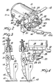
- the device according to this invention is generally designated by the reference numeral 1. It is applied, in Figure 1, to a folding machine 2 known per se, of which some operational members are shown schematically.
- a jaw 9 also known per se, is placed beneath the working surface 3 and moves cyclically upwards to engage a hide 10, or the like laminar element, against the base of the shoe 8.
- a folding machine 2 there are also provided members for cyclically advancing the hide or laminar element 10 in the form of a hammer and underlying anvil which clamp the upturned edge and cause it to adhere to the glue dispensed from the shoe 8.
- the hammer and anvil drive the hide 10 forward with the jaw 9, aligned to the shoe 8, disengaged from the shoe.
- the hammer and anvil are not shown because removed from the guide 4.
- the guiding device 1 is engaged with a frame 2a of the folding machine 2 and comprises supporting and drive means 11 for a working element 15 which is oscillable and in contact with the hide 10.
- the guiding device 1 is engaged with the frame 2a through a small shaft 12 substantially parallel to the working surface 3 and projecting cantilever-fashion, after the manner of an appendage, from a plate-shaped holder 13, to which the entire guiding device 1 is led.
- the small shaft 12 is adapted to allow the guiding device 1 to perform oscillations about the shaft 12 axis, substantially toward the cited hammer and anvil.
- the oscillations may be driven by members, not shown, such as cams and cam followers, and have the effect of assisting a concurrent movement of the hide 10 with that already imparted by said anvil and hammer.
- the holder 13 engages, at a lowation removed from the small shaft 12, a bar-like body 14 which extends in a transverse direction to the working surface 3 until it terminates with the cited working element, formed by a small rod 15 also lying transversely to the working surface 3 and terminated with an active end 15a.
- the active end 15a is pointed.
- the small rod or working element 15 is oscillable axially against an elastic means 14a formed by a small compression spring housed inside the bar-like body 14.
- the bar-like body 14 is engaged with the holder 13 by means of a first swivel connection 18 defined by a tang 16 in continuation of the bar-like body 14 and a first pin 17 substantially perpendicular to the tang 16 and substantially parallel to the working surface 3.
- the first pin 17 is penetrated slidably by the tang 16 and both the tang 16 and the first pin 17 have circular cross-sections, so as to permit of their rotation about respective axes.
- the axis of rotation of the first pin 17 defines, in the first swivel connection 18, an axis of oscillation 18a of the bar-like body 14, whereas the axis of the tang 16 defines a lifting and lowering axis of the bar-like body 14.
- a spring element 19 is wound which is formed by a compression spring closed between the first pin 17 and washers 20 fast with the tang 16.
- the bar-like body 14 is engaged, at a second pin 21, by a crosspiece-like body 22 which flanks the holder 13 at a position away therefrom and is terminated with a small plate 22a engaged centrally by a second swivel connection 23.
- the second swivel connection 23 has a part-spherical bulb 24 penetrated by a pin 25. The latter extends transversely of the small plate 22a and forms an eccentric or cam 29 with the second swivel connection 23.
- the pin 25 is affixed and parallel, in an offcentered position, to a drive shaft 26 penetrating the holder 13 and being driven by an electric motor 32 preferably a DC motor.
- a face cam 27 acting on a cam follower 28 engaged with the crosspiece-like body 22.
- the cam follower 28 is a small wheel whose axis is substantially parallel to the main dimension of the crosspiece-like body 22.
- the cam 27 acts on the cam follower 28 against the elastic bias of the compression spring 19 fitted over the tang 16 of the bar-like body 14.
- the cam 27 and the cam 29 defined by the pin 25 and second swivel connection 23 impart cyclic oscillations on the active end 15a which define a path having a raised section 30 and a contact section 31 off/with the hide 10, as shown in Figures 3 to 7.
- Figure 7 is substantially coincident with Figure 3 and shows the device return to the original position.
- Another important feature is the limited contact of the device with the hide being processed. This limited contact, being punctiform in the instance shown, causes the thrust from the active end 15a to impart no definite angular direction to the hide as may be inappropriate. The hide is merely pushed to a position against the working members of the machine and not forced out of its angular position. Therefore, it may even in this case adjust itself into the most appropriate angular position as defined by the working members engaging it.
- the device 1 it is also possible to oscillate the device 1 about the axis of the small shaft 12 by introducing a parallel movement to the entrainment movement of the cited anvil and hammer.
- the invention is susceptible to many modifications and variations.
- the assembly of the face cam 27 and cam follower 28, acting against the compression spring 19 may be replaced with a dual or desmodromic cam which allows elimination of the compression spring 19.
- the active end 15a may be provided with both a point and small teeth set close together to bite less deeply into the hide or the like.
- the electric motor 32 may be replaced with flexible mechanical linkages led to the motor of the folding machine and formed by belts and pulleys, for example.
Landscapes
- Engineering & Computer Science (AREA)
- Manufacturing & Machinery (AREA)
- Mechanical Engineering (AREA)
- Chemical & Material Sciences (AREA)
- Organic Chemistry (AREA)
- Folding Of Thin Sheet-Like Materials, Special Discharging Devices, And Others (AREA)
- Treatment And Processing Of Natural Fur Or Leather (AREA)
Applications Claiming Priority (2)
| Application Number | Priority Date | Filing Date | Title |
|---|---|---|---|
| IT2167688 | 1988-08-05 | ||
| IT8821676A IT1226830B (it) | 1988-08-05 | 1988-08-05 | Dispositivo di guida di elementi laminari in lavorazione, particolarmente per macchine ripiegatrici di pelli e materiali sintetici. |
Publications (2)
| Publication Number | Publication Date |
|---|---|
| EP0353537A2 true EP0353537A2 (de) | 1990-02-07 |
| EP0353537A3 EP0353537A3 (de) | 1992-01-02 |
Family
ID=11185235
Family Applications (1)
| Application Number | Title | Priority Date | Filing Date |
|---|---|---|---|
| EP19890113126 Withdrawn EP0353537A3 (de) | 1988-08-05 | 1989-07-18 | Vorrichtung zum Führen von lamellierten Teilen für eine Behandlung, insbesondere für Häute- und Kunststoffmaterial-Faltmaschinen |
Country Status (6)
| Country | Link |
|---|---|
| US (1) | US5001797A (de) |
| EP (1) | EP0353537A3 (de) |
| BR (1) | BR8903926A (de) |
| CS (1) | CS467889A2 (de) |
| HU (1) | HUT60787A (de) |
| IT (1) | IT1226830B (de) |
Cited By (1)
| Publication number | Priority date | Publication date | Assignee | Title |
|---|---|---|---|---|
| EP3106525A1 (de) * | 2015-06-17 | 2016-12-21 | Overmec S.r.l. | Verbesserte lineare einreich-/faltmaschine |
Family Cites Families (13)
| Publication number | Priority date | Publication date | Assignee | Title |
|---|---|---|---|---|
| US2086138A (en) * | 1936-02-08 | 1937-07-06 | Fred M Roque | Paper feeding device |
| US2231874A (en) * | 1939-09-11 | 1941-02-18 | Peerless Machinery Co | Folding machine |
| US2311085A (en) * | 1942-04-28 | 1943-02-16 | John W Rudolph | Folding machine |
| GB722446A (en) * | 1952-04-08 | 1955-01-26 | British United Shoe Machinery | Improvements in or relating to the folding of binding material around the edges of workpieces |
| US2712662A (en) * | 1953-10-29 | 1955-07-12 | United Shoe Machinery Corp | Creaser foot carriers for folding machines |
| US2881456A (en) * | 1957-09-03 | 1959-04-14 | Nicodemo J Agostino | Shoe uppers and their manufacture |
| US2979745A (en) * | 1959-07-17 | 1961-04-18 | United Shoe Machinery Corp | Work feeding and guiding means |
| US3088144A (en) * | 1961-04-18 | 1963-05-07 | United Shoe Machinery Corp | Machines for operating upon margins of workpieces |
| US3121242A (en) * | 1962-11-29 | 1964-02-18 | United Shoe Machinery Corp | Thermo-cementing and folding machines |
| GB1168898A (en) * | 1967-03-09 | 1969-10-29 | Alberto Bocca | Apparatus for Folding the Edges of a Flexible Sheet |
| FR2285323A1 (fr) * | 1974-09-18 | 1976-04-16 | Cellophane Sa | Amelioration aux dispositifs d'alimentation en feuilles |
| US4557787A (en) * | 1982-11-24 | 1985-12-10 | Usm Corporation | Automatically controlled thermo-cementing and folding machine |
| GB8316899D0 (en) * | 1983-06-22 | 1983-07-27 | British United Shoe Machinery | Folding machines |
-
1988
- 1988-08-05 IT IT8821676A patent/IT1226830B/it active
-
1989
- 1989-07-18 EP EP19890113126 patent/EP0353537A3/de not_active Withdrawn
- 1989-07-31 US US07/386,919 patent/US5001797A/en not_active Expired - Fee Related
- 1989-08-02 HU HU893941A patent/HUT60787A/hu unknown
- 1989-08-04 CS CS894678A patent/CS467889A2/cs unknown
- 1989-08-04 BR BR898903926A patent/BR8903926A/pt unknown
Cited By (1)
| Publication number | Priority date | Publication date | Assignee | Title |
|---|---|---|---|---|
| EP3106525A1 (de) * | 2015-06-17 | 2016-12-21 | Overmec S.r.l. | Verbesserte lineare einreich-/faltmaschine |
Also Published As
| Publication number | Publication date |
|---|---|
| CS467889A2 (en) | 1991-07-16 |
| IT1226830B (it) | 1991-02-19 |
| IT8821676A0 (it) | 1988-08-05 |
| EP0353537A3 (de) | 1992-01-02 |
| BR8903926A (pt) | 1990-03-27 |
| HUT60787A (en) | 1992-10-28 |
| US5001797A (en) | 1991-03-26 |
Similar Documents
| Publication | Publication Date | Title |
|---|---|---|
| CN106607952B (zh) | 全自动制袋机手挽送料切料装置 | |
| US5001797A (en) | Device for guiding laminar elements for processing, particularly intended for hide and synthetic material folding machines | |
| EP0340695A3 (de) | Maschine zum Kleben und Falten von blattförmigen Materialien | |
| US4659001A (en) | Machine for applying articles of hardware to tensioned textile materials | |
| US2701877A (en) | Apparatus for forming and applying top stops | |
| US3798108A (en) | Apparatus for dispensing tape | |
| US2793856A (en) | Apparatus for dispensing sealing strips or the like | |
| US2216453A (en) | Stapling machine | |
| US3088144A (en) | Machines for operating upon margins of workpieces | |
| US3754491A (en) | Delivery and cutting apparatus for tape | |
| US3475256A (en) | Bordering machine | |
| US3126853A (en) | Stitching to shoes or the like | |
| US3086209A (en) | Method of applying a flexible covering material to a rigid backing | |
| US2173958A (en) | Insole-covering machine | |
| US3445872A (en) | Automatic machine for manufacturing footwear | |
| JPH0435320Y2 (de) | ||
| US3397415A (en) | Fully automatic machine for the working of sole edges on crude soles | |
| US2365663A (en) | Strip cutter | |
| KR20040000782A (ko) | 모자챙의 재봉장치 | |
| US2335267A (en) | Tape-applying machine | |
| KR0126403B1 (ko) | 금속 테이프 절단장치 | |
| JPH0644624Y2 (ja) | 冊子用小口断裁機 | |
| US1522974A (en) | Wire-stitching machine | |
| US1293339A (en) | Labeling and stapling machine. | |
| US3016552A (en) | Machine for folding the edges of shoe uppers |
Legal Events
| Date | Code | Title | Description |
|---|---|---|---|
| PUAI | Public reference made under article 153(3) epc to a published international application that has entered the european phase |
Free format text: ORIGINAL CODE: 0009012 |
|
| AK | Designated contracting states |
Kind code of ref document: A2 Designated state(s): DE ES FR GB |
|
| PUAL | Search report despatched |
Free format text: ORIGINAL CODE: 0009013 |
|
| AK | Designated contracting states |
Kind code of ref document: A3 Designated state(s): DE ES FR GB |
|
| STAA | Information on the status of an ep patent application or granted ep patent |
Free format text: STATUS: THE APPLICATION IS DEEMED TO BE WITHDRAWN |
|
| 18D | Application deemed to be withdrawn |
Effective date: 19920201 |