EP0353556B1 - Dispositif pour le stockage d'objets de grande longueur - Google Patents
Dispositif pour le stockage d'objets de grande longueur Download PDFInfo
- Publication number
- EP0353556B1 EP0353556B1 EP89113415A EP89113415A EP0353556B1 EP 0353556 B1 EP0353556 B1 EP 0353556B1 EP 89113415 A EP89113415 A EP 89113415A EP 89113415 A EP89113415 A EP 89113415A EP 0353556 B1 EP0353556 B1 EP 0353556B1
- Authority
- EP
- European Patent Office
- Prior art keywords
- container
- transverse rollers
- chain
- drive
- rollers
- Prior art date
- Legal status (The legal status is an assumption and is not a legal conclusion. Google has not performed a legal analysis and makes no representation as to the accuracy of the status listed.)
- Expired - Lifetime
Links
Images



Classifications
-
- B—PERFORMING OPERATIONS; TRANSPORTING
- B65—CONVEYING; PACKING; STORING; HANDLING THIN OR FILAMENTARY MATERIAL
- B65G—TRANSPORT OR STORAGE DEVICES, e.g. CONVEYORS FOR LOADING OR TIPPING, SHOP CONVEYOR SYSTEMS OR PNEUMATIC TUBE CONVEYORS
- B65G1/00—Storing articles, individually or in orderly arrangement, in warehouses or magazines
- B65G1/02—Storage devices
- B65G1/04—Storage devices mechanical
- B65G1/0407—Storage devices mechanical using stacker cranes
- B65G1/0414—Storage devices mechanical using stacker cranes provided with satellite cars adapted to travel in storage racks
-
- B—PERFORMING OPERATIONS; TRANSPORTING
- B65—CONVEYING; PACKING; STORING; HANDLING THIN OR FILAMENTARY MATERIAL
- B65G—TRANSPORT OR STORAGE DEVICES, e.g. CONVEYORS FOR LOADING OR TIPPING, SHOP CONVEYOR SYSTEMS OR PNEUMATIC TUBE CONVEYORS
- B65G1/00—Storing articles, individually or in orderly arrangement, in warehouses or magazines
- B65G1/02—Storage devices
- B65G1/04—Storage devices mechanical
- B65G1/0442—Storage devices mechanical for elongated articles
Definitions
- the invention relates to a device for storing long goods, for example pipes, rods or the like, on a shelf which comprises a plurality of receiving spaces for long goods, with a mobile receiving carriage which can be moved from the front side into the receiving spaces of the shelf by means of a drive device is.
- the rack arrangement has receiving compartments with associated, displaceable receiving carriages and a separate loading and unloading carriage. This can be moved on the opening side of the storage compartments transversely to these and has a height-adjustable platform which can be aligned with the individual storage compartments for the purpose of taking over the storage trolley.
- the loading and unloading trolley runs on tracks or in a recessed track by means of rollers and is thus bound to the track or lane.
- the known design is also structurally extremely complex and unsuitable to transport long goods, such as pipes, rods or the like, without using lanes or rails.
- Another known device (DE-A-2 243 107) relates to a pallet truck for loading a high-bay warehouse with a shelf operating device and a lifting platform that can be moved in front of the high-bay warehouse.
- the pallet truck can be moved in rails that are installed both in the lifting platform and in individual shelf compartments, and has caterpillar tracks on the side to make it easier to move between these rails even when the rails are inexactly aligned on the high rack and in the lifting platform, even when doing so larger distances must be bridged between the rails.
- the invention has for its object to provide a device with the features of the generic term so that rails are no longer required to retract the receiving goods receiving the long goods and thus an individual constructive adjustment of the receiving carriage and the shelf is no longer necessary, so that the shelves easier, lighter in weight and thus cheaper to manufacture.
- the receiving carriage is designed as a trough-like, open-sided container, which is equipped for the transport of the long goods with caterpillars, which are deflected via end sprockets, this can be used in all conventional shelves, without special rails adapted to the track width of the container have to be. Accordingly, the arrangement of special L- and U-shaped profiled guide rails on the shelves not necessary anymore; the trough-shaped, caterpillar-equipped receiving trolley can thus also be inserted into existing shelves, which are only formed by vertical stands and horizontal crossbars connecting and stiffening them, provided that the width of the individual storage spaces on top of and next to each other is sufficiently large.
- a further advantage lies in the fact that several trough-like containers provided with caterpillar tracks can be inserted next to one another into correspondingly wide receiving spaces due to the design according to the invention. Furthermore, since a drive device for the mobile container is arranged on the container itself and the long goods are supported on transverse rollers in the container, easy loading and unloading as well as simple, effortless transport of the long goods is ensured even with long goods weighing tons.
- the lower section thereof is designed as a guide profile open at the bottom, which guides the caterpillar chain and from which the caterpillar chain protrudes with its running surface.
- This arrangement not only contributes to the increased stability and torsional rigidity of the trough-shaped container, but also serves for the exact guidance of the caterpillar chain and thus for the targeted positioning of the container in the receiving spaces.
- the drive device can be equipped with means which ensure a synchronous drive of both caterpillar tracks.
- Different versions of this are possible; one may consist in that a motor equipped with two shaft ends acts on the chain wheels or that a drive motor equipped with a drive shaft acts equally on both caterpillar tracks via a connecting shaft. If a low speed drive motor is used to move the container at a reasonable speed, a reduction gear and the motor can be directly coupled to the sprockets.
- An embodiment variant of the drive device also consists in that a drive motor acts on the running surfaces of the crawler belt with the interposition of friction wheels.
- the picking process is ended by the long goods being deposited on the cross members in the intended receiving space.
- the removal of the long goods from the container and deposits on the cross members can be done, for example, by the fact that a slide is provided which has the inner cross-sectional shape of the container and is movable relative to the container, so that when the container is extended from a receiving space, the long goods are opened the cross rollers are rolled out of the container.
- the number of cross rollers must be measured. It has been found that in the case of the commercial dimensions of long goods, which are approximately 6 m to 7 m, at least five transverse rollers, but preferably seven transverse rollers, are to be provided. These transverse rollers should have the same diameter and be arranged at approximately the same intervals over the length of the container. To discharge the long goods, it is particularly expedient that at least a part of the total number of transverse rollers can be driven, so that the long goods are moved out of the container by the rotational movement of the rollers. In this regard, it is particularly advantageous that the transverse rollers are provided with a chain or drive wheel, over which a conveyor chain or a drive belt is stretched.
- the caterpillar tracks, the conveyor chain and / or the drive belt are provided with tensioning means, which are preferably designed as tensioning rollers.
- a cover attached to one of the side wall parts which covers the drive means of the transverse rollers. It is particularly expedient for the cover to run at a short distance above the transverse rollers and to have downwardly projecting sections in the region between the transverse rollers. In this way it is ensured that the loading of the container with long goods is possible without special precautionary measures and the drive means for the transverse rollers are protected from any damage with certainty.
- a particularly preferred embodiment of the drive of the transverse rollers consists in that the conveyor chain is tensioned via a drive sprocket which is mounted on a shaft together with one of the sprockets of the caterpillar tracks, but can be driven independently of this.
- This independent driving is important because the transverse rollers of the transport of the long goods are fixed up to the receiving space and can only be driven in the receiving space provided for storing the long goods.
- the drive sprocket can be connected to the sprocket of the caterpillar chain if necessary via a clutch. This can suitably be a claw coupling or a similar type of coupling in which the coupling parts are in positive engagement.
- a particularly suitable embodiment of the invention is given when the direction of rotation of the transverse rollers is opposite is the direction of movement of the container, the speed on the lateral surface of the transverse rollers being equal to the speed of the container.
- the speed on the lateral surface of the transverse rollers being equal to the speed of the container.
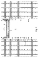
- Fig. 1 shows the schematic structure of a long goods store, of which two rows of shelves 1a and 1b are shown with an aisle 2 located between them.
- a lifting platform 3 can be moved horizontally and vertically between the rows of shelves 1a and 1b.
- the lifting platform 3 is used for conveying the height of a trough-shaped container 4 to the individual receiving spaces 5, one above the other and in the horizontal direction, which are formed by vertical stands 6 and horizontal cross bars 7.
- the receiving spaces 5 are used to store the different types of long goods 8, such as rods, pipes or the like.
- Lowerable slides 9 are arranged on the lifting device 3, the function of which will be explained in more detail later in FIG. 2.
- the container 4 is equipped with caterpillar tracks, by means of which the container 4 can be moved in and out in the direction of arrow F into the receiving spaces 5.
- the structure of the device is described in more detail with reference to the other figures.
- Fig. 2 shows a section through a container 4 for receiving long goods
- the trough shape of the container 4 is formed by the side wall parts 10 and the transverse rollers 11 arranged between them. Since the transverse rollers 11 rotatably mounted on the wall parts 10 could not produce the required rigidity of the trough-shaped container 4, the side wall parts 10 are - as shown in FIG. 3 - joined together to form a rigid frame via welded-on cross members 12. However, since the upper surface lines 11a of the transverse rollers 11 lie higher than the upper edges 12a of the transverse beams 12 (see FIG. 3), the transverse rollers 11 form a support and thus the bottom of the container 4 on which the (not shown in FIG. 2) ) Long goods lies.
- the container 4 drawn in cross section is shown in Fig. 2 so that it is located in a receiving space 5 of the shelf between the stand 6 and 7 cross members.
- a slide 9 is also shown in the lowered position, by means of which the long goods are held in their position when the container 4 is extended from the receiving space 5 and are thus slid out of the container 4 on the rollers 11.
- the lower part of the sprocket 13 protruding a corresponding opening 15 in the lower portion of the wall part 10 in a guide profile 16 connected to this lower wall part.
- An endless caterpillar track 17 is stretched over the chain wheels 13, the chains being guided exactly in the guide profiles 16.
- the lower links of the caterpillar track 17 protrude from the guide profiles 16 on the underside and thus form the running surface 18 of the caterpillar tracks 17. It goes without saying that the guide profiles 16 have the openings 15 only in the area of the sprockets 13, but for the rest the side wall parts are closed, as can be seen from FIGS. 2 and 3.
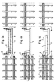
- the container 4 which contains the long goods 8 and which is located on the lifting platform 3, is brought into a position in which the container is positioned in an exactly aligned manner in front of an empty receiving space 5.
- the container 4 the caterpillar tracks of which can be driven by a drive device, is completely moved into the receiving space 5, as a result of which the long goods to be picked are also completely located within the receiving space 5.
- Fig. 4b The slider 9 arranged on the lifting platform 3 is then lowered, so that an end face of the container 4 closes while maintaining a small distance from the transverse rollers 11 and lateral wall parts 10.
- FIG. 2 With regard to the position that the slide 9 assumes, reference is made to the illustration in FIG. 2.
- the container 4 is moved out of the receiving space back onto the lifting platform 3, as shown in FIG. 4c. Since the lowered slider 9 holds the long goods 8 in place, the long goods roll off Cross rollers 11 down and lies on the cross bars 7 of the shelf row 1a. The empty container 4 is then available for further filling with long goods and for the next picking process.
- FIG. 5 again shows a section through a container 4, which is located in a receiving space 5, the section being made through the axes of the chain wheels. Since this is a representation which essentially corresponds to that in FIG. 2, the reference numerals of FIG. 2 are used for the same parts.
- FIG. 5 shows the long goods 8 lying on the transverse rollers 11 in the form of round bars.
- the alternative embodiment of FIG. 5 differs from that in FIG. 2 in that the transverse rollers 11 are provided with a drive device by means of which the rollers 11 can be set in rotation and thus deposit the long goods.
- the sprocket 13 shown on the left in FIG. 5 is fastened to an elongated shaft 19 which projects into the interior of the container 4.
- a drive sprocket 20 On a section of this extended shaft 19 there is a drive sprocket 20, which is freely supported on the shaft 19.
- a conveyor chain 21 is tensioned over the drive sprocket 20 and is used to drive the transverse rollers 11 as required.
- a coupling part 23 On a pin 22 of the shaft 19, a coupling part 23 is fastened in a rotationally fixed but axially displaceable manner, which can be brought into engagement in the manner of a claw coupling with coupling bolts 24 projecting from the drive sprocket 20 in the axial direction.
- Fig. 5 the upper half of the coupling part 23 is shown in the uncoupled position and the lower half 23 'of the coupling part in the coupled state.
- This drive mechanism for the transverse rollers 11 is covered by a sheet metal hood 25 screwed onto the side wall part 10. This sheet metal hood 25 serves on the one hand as accident prevention protection and on the other hand to protect the drive means from being damaged by the long goods 8.
- Fig. 6 shows a section through a device according to FIG. 5, but in a different plane, and more in the middle of the container 4. From this illustration it can be seen that the caterpillar tracks 17 both with respect to the upper horizontal movement - ie their upper run - As well as the lower horizontal movement - so their lower run - are guided on slide rails 26 and 27.
- the slide rails 26 prevent sagging of the caterpillar track 17 and the slide rails 27 guarantee that a smooth course of the caterpillar chain is ensured even when the ground is uneven or when crossing cross bars 7.
- the transverse roller 11 has a sprocket 28 at its end shown on the left in FIG. 6, which is non-rotatably connected to the transverse roller 11 and which can be driven by the conveyor chain 21.
- FIG. 7 shows a section of an alternative embodiment to FIG. 3, namely the arrangement of a cross member 12 on a side wall part 10 or guide profile 16.
- the cross member 12 is fastened to an intermediate piece 31 which carries a slide rail 30 on its upper side, on which the conveyor chain 21 is guided in the area between two adjacent sprockets of the transverse rollers.
- the section 25 'of the sheet metal hood can be fastened by means of screws, so that the drive system for Is easily accessible for purposes of maintenance or repair work.
- FIG. 8 shows a part of a side view or a longitudinal section of the container according to FIGS. 5 and 6.
- the container 4 rests with the running surface 18 of the crawler belt 17 on the cross bars 7 of the shelf.
- a cross member 12 is arranged between two transverse rollers 11 which, according to the illustration in FIG. 3, forms the framework of the container 4 together with the side wall parts 10.
- the coupling part 23, in which the coupling bolts 24 of the drive sprocket 20 engage, is located on the journal 22 of the shaft 19.
- the conveyor chain 21 is guided over the drive sprocket 20 and runs in the lower region over the upper circumference of the sprockets 28.
- a tension roller 32 is also provided for tensioning the conveyor chain 21.
- the caterpillar chain 17 is placed over the outer ring gear of the chain wheel 13 and is guided to the slide rail 26 via a height-adjustable tensioning roller 33.
- the special guidance of the conveyor chain 21 over the upper part of the sprockets 28 results in a rotation of the transverse rollers 11 counterclockwise when the container 4 moves to the right in the drawing, which of course presupposes that the clutch is engaged.
- the long goods located in the container 4 remain virtually fixed, d. H. the long product does not move relative to the shelf and is rolled out of the container 4 by means of the transverse rollers 11 at the same speed as it moves out of the shelf.
- the long goods thus lay down on the cross bars 7 of the shelf, as has already been described for FIG. 4.
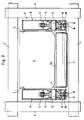
- FIG. 9 shows a top view of part of the container 4 according to FIG. 8.
- the reference numeral 6 is again a vertical stand and 7 a cross member of the shelf designated.
- a cross member 12 is welded to the side wall part 10 and runs parallel to transverse rollers 11.
- the transverse rollers 11 have chain wheels 28, over which a conveyor chain 21 is placed.
- the conveyor chain 21 is tensioned via a drive sprocket 20 which is mounted on a shaft 19 together with a further sprocket 13 and a coupling part 23.
- the caterpillar track 17, on which the container 4 can be moved, runs over the chain wheel 13.
- a coupling lever 34 is articulated on the coupling part 23, by actuating it in the position shown in broken lines, the coupling part 23 can be brought into engagement with the coupling bolts 24, as a result of which the transverse rollers 11 are driven.
- the sheet metal hood 25 covers the entire area of the drive mechanism of the transverse rollers 11 including the associated coupling in the front part of the container 4.
- FIG. 10 shows an embodiment variant of FIG. 2 with a drive device mounted on the container 4.
- the drive device comprises a motor 35, on the shaft of which a toothed pinion 36 is fastened, which engages in an intermediate wheel 37 designed as a toothed wheel.
- the intermediate gear 37 is fastened on a connecting shaft 38 which is guided in a connecting tube 39 between the side wall parts 10.
- a second idler gear 37 ' is fastened to it, which corresponds exactly to the first idler gear 37 with respect to the extent and number of teeth, which engages with the pinion gear 36.
- the intermediate wheels 37 and 37 ' engage with their respective sprockets in gears 40 and 40', which are connected to friction wheels 41 and 41 'of the shafts 42 and 42'.
- the friction wheels 41 and 41 ' are in frictional contact with the crawler belts 17 and thus transmit the rotary movement of the drive motor 35 at a correspondingly reduced speed to the caterpillar tracks 17.
- a good one Friction between the caterpillar tracks 17 and the friction wheels 41 and 41 ' is achieved in that the friction wheels 41 and 41' are provided with a covering 43 made of hard rubber.
- FIG. 11 shows a view of the container 4 according to FIG. 8, which is equipped with a drive device according to FIG. 10. Since the container 4 essentially corresponds to that of FIG. 8, only the additionally provided drive device will be discussed at this point.
- the drive device comprises the motor 35, which can be, for example, an electric or hydraulic motor or a pneumatic drive.
- the motor 35 drives an intermediate wheel 37 via a pinion 36, which is fastened on a connecting shaft 38.
- the connecting shaft 38 is located in a connecting tube 39.
- the intermediate gear 37 engages with its ring gear in a gear 40 which is arranged with a friction wheel 41 on a common shaft 42.
- the friction wheel 41 is in frictional connection with the running surface of the caterpillar track 17.
- the entire drive device is arranged in a support frame, which comprises side frame parts 44 and the connecting tube 39 connecting them.
- the drive device is hooked onto a fastening bolt 46 with a hook 45 and tensioned by means of a tensioning device 47 such that the required frictional force prevails between the friction wheel 41 and the crawler belt 17.
Landscapes
- Engineering & Computer Science (AREA)
- Mechanical Engineering (AREA)
- Warehouses Or Storage Devices (AREA)
- Vending Machines For Individual Products (AREA)
Claims (13)
- Dispositif pour le stockage d'objets de grande longueur, par exemple de tubes, tiges ou analogues, dans un rayonnage qui comporte une multiplicité d'espaces récepteurs pour les objets de grande longueur, comprenant un chariot récepteur mobile qui peut être introduit par le côté frontal dans les espaces récepteurs du rayonnage au moyen d'un organe d'entraînement,
caractérisé en ce que le chariot récepteur est réalisé sous la forme d'un bac (4) muni de parois et ouvert du côté frontal, qui, pour le transport des objets de grande longueur, est muni de chaînes à chenilles (17), lesquelles sont renvoyées par des roues à chaînes (13) aux extrémités, et en ce qu'un organe d'entraînement (35 à 47) pour le bac mobile (4) est agencé sur le bac lui-même et en ce que le produit de grande longueur (8) est supporté par des rouleaux transversaux (11) dans le bac. - Dispositif selon la revendication 1, caractérisé en ce que les chaînes à chenilles (17) sont prévues sur les côtés longitudinaux du bac (4), les roues à chaînes (13) étant disposées chacune dans des régions terminales d'éléments de paroi (10), et en ce que des glissières (26,27) et/ou des rouleaux de guidage pour les chaînes à chenilles (17) sont prévus entre une roue à chaînes antérieure et une roue à chaînes postérieure d'un élément de paroi (10).
- Dispositif selon l'une des revendications 1 et 2, caractérisé en ce que la section inférieure des éléments de paroi (10) est réalisée sous la forme d'un profil de guidage (16) ouvert vers le bas, à partir duquel les chaînes à chenilles (17) font saillie par leurs surfaces de roulement (18).
- Dispositif selon l'une des revendications 1 à 3, caractérisé en ce que des moyens (37',38,40',41') sont prévus pour l'entraînement synchronisé des deux chaînes à chenilles (17).
- Dispositif selon l'une des revendications 1 à 4, caractérisé par un dispositif d'accouplement de l'organe d'entraînement (35 à 47) avec les axes (14) des roues à chaînes (13).
- Dispositif selon la revendication 5, caractérisé en ce que l'organe d'entraînement agit par l'intermédiaire de roues de friction (41,41') sur les surfaces de roulement (18) des chaînes à chenilles (17).
- Dispositif selon l'une des revendications 1 à 6, caractérisé en ce qu'il est prévu un tiroir (9) qui a la forme de la section transversale du bac (4) et qui est déplaçable par rapport au bac (4) de telle sorte que, lorsque le bac (4) sort d'un espace de réception (5), l'objet de grande longueur (8) peut être sorti du bac (4) en roulant sur les rouleaux transversaux (11).
- Dispositif selon l'une des revendications 1 à 7, caractérisé en ce qu'une partie au moins de la totalité des rouleaux transversaux (11) est entraînable.
- Dispositif selon la revendication 8, caractérisé en ce que les rouleaux transversaux (11) sont munis chacun de roues à chaînes ou de roues d'entraînement (28), autour desquelles une chaîne transporteuse (21) ou une courroie d'entraînement est mise sous tension.
- Dispositif selon l'une des revendications 1 à 9, caractérisé en ce que sur l'un des éléments de paroi latéraux (10) est prévu un couvercle fixe (25) qui recouvre les moyens d'entraînement (21,28) des rouleaux transversaux (11).
- Dispositif selon l'une des revendications 8 à 10, caractérisé en ce que la chaîne transporteuse (21) est mise sous tension autour d'une roue à chaîne d'entraînement (20), laquelle est montée conjointement avec une des roues à chaîne (13) des chaînes à chenilles (17) sur un axe (19) et peut être entraînée facultativement par celui-ci.
- Dispositif selon l'une des revendications 1 à 11, caractérisé en ce que le sens de rotation des rouleaux transversaux (11) est opposé au sens de déplacement (F) du bac (4), la vitesse à la surface de l'enveloppe des rouleaux transversaux (11) étant égale à la vitesse du bac (4).
- Dispositif selon la revendication 12, caractérisé en ce que l'accouplement (23,24) est un accouplement à griffes et est muni d'un levier d'actionnement (34).
Priority Applications (1)
| Application Number | Priority Date | Filing Date | Title |
|---|---|---|---|
| AT89113415T ATE87585T1 (de) | 1988-07-28 | 1989-07-21 | Vorrichtung zur einlagerung von langgut. |
Applications Claiming Priority (2)
| Application Number | Priority Date | Filing Date | Title |
|---|---|---|---|
| DE3825570 | 1988-07-28 | ||
| DE3825570A DE3825570A1 (de) | 1988-07-28 | 1988-07-28 | Vorrichtung zur einlagerung von langgut |
Publications (2)
| Publication Number | Publication Date |
|---|---|
| EP0353556A1 EP0353556A1 (fr) | 1990-02-07 |
| EP0353556B1 true EP0353556B1 (fr) | 1993-03-31 |
Family
ID=6359700
Family Applications (1)
| Application Number | Title | Priority Date | Filing Date |
|---|---|---|---|
| EP89113415A Expired - Lifetime EP0353556B1 (fr) | 1988-07-28 | 1989-07-21 | Dispositif pour le stockage d'objets de grande longueur |
Country Status (4)
| Country | Link |
|---|---|
| US (1) | US4993905A (fr) |
| EP (1) | EP0353556B1 (fr) |
| AT (1) | ATE87585T1 (fr) |
| DE (2) | DE3825570A1 (fr) |
Families Citing this family (18)
| Publication number | Priority date | Publication date | Assignee | Title |
|---|---|---|---|---|
| IT1294287B1 (it) * | 1997-07-30 | 1999-03-24 | Fata Automation | Magazzino a celle con carri di trasporto a movimentazione idropneumatica |
| KR20000004694A (ko) * | 1998-06-30 | 2000-01-25 | 이해규 | 라이저 이송 장치 |
| US6179541B1 (en) | 1999-10-25 | 2001-01-30 | Sylvain Rioux | Transfer device for lumber packs and other loads |
| AU2001228922A1 (en) * | 2000-01-13 | 2001-07-24 | Ps-Design As | Horizontal pipe handling device |
| US20050095093A1 (en) * | 2002-02-25 | 2005-05-05 | Rudolf Hansl | Storage retrieval system comprising a load receiving element |
| ITMI20020669A1 (it) * | 2002-03-29 | 2003-09-29 | Schnell Spa | Dispositivo per la raccolta e la movimentazione di profilati metallici particolarmente per tondini di acciaio per la produzione di armature |
| US9321591B2 (en) | 2009-04-10 | 2016-04-26 | Symbotic, LLC | Autonomous transports for storage and retrieval systems |
| US8740538B2 (en) | 2009-04-10 | 2014-06-03 | Symbotic, LLC | Storage and retrieval system |
| US9187244B2 (en) | 2010-12-15 | 2015-11-17 | Symbotic, LLC | BOT payload alignment and sensing |
| US11078017B2 (en) | 2010-12-15 | 2021-08-03 | Symbotic Llc | Automated bot with transfer arm |
| US9561905B2 (en) | 2010-12-15 | 2017-02-07 | Symbotic, LLC | Autonomous transport vehicle |
| US8965619B2 (en) | 2010-12-15 | 2015-02-24 | Symbotic, LLC | Bot having high speed stability |
| US9499338B2 (en) | 2010-12-15 | 2016-11-22 | Symbotic, LLC | Automated bot transfer arm drive system |
| US8696010B2 (en) | 2010-12-15 | 2014-04-15 | Symbotic, LLC | Suspension system for autonomous transports |
| US8960825B2 (en) | 2011-10-04 | 2015-02-24 | Lg Electronics Inc. | Refrigerator |
| CN105705441B (zh) | 2013-09-13 | 2018-04-10 | 西姆伯蒂克有限责任公司 | 自主运输车、存储和取回系统及在该系统内传递拣选面的方法 |
| EP4087797B1 (fr) | 2020-01-09 | 2024-05-29 | System Logistics S.P.A. | Dispositif de déplacement |
| CN111409994A (zh) * | 2020-05-08 | 2020-07-14 | 深圳市航瑞物流自动化有限公司 | 一种超长货物自动存取机构 |
Family Cites Families (19)
| Publication number | Priority date | Publication date | Assignee | Title |
|---|---|---|---|---|
| US2406992A (en) * | 1944-02-07 | 1946-09-03 | Maui Pineapple Company Ltd | Method and apparatus for loading and storing pineapples |
| US3214934A (en) * | 1961-12-07 | 1965-11-02 | Raymor Corp | Refrigerated storage house |
| US3474916A (en) * | 1968-04-05 | 1969-10-28 | Joseph E Mcwilliams | Apparatus for loading bagged mail from a loading dock into a highway vehicle |
| DE2243107C2 (de) * | 1969-11-17 | 1984-08-09 | Industrie-Planungs-Gesellschaft Mbh, 8380 Landau | Palettenunterfahrwagen zur Beschickung der einzelnen Regalfächer eines Hochregallagers |
| US4063653A (en) * | 1976-10-05 | 1977-12-20 | Oehler, Wyhlen, Lagertechnic Ag | Automatic high shelf store |
| JPS5391276A (en) * | 1977-01-21 | 1978-08-10 | Daifuku Co Ltd | Pull-in conveyer |
| US4205934A (en) * | 1977-05-17 | 1980-06-03 | The British Mathews Limited | Stacking apparatus |
| CH620883A5 (en) * | 1977-07-14 | 1980-12-31 | Kempf & Co Ag | Device for stacking drums provided with stacking grooves |
| SE407047B (sv) * | 1977-08-24 | 1979-03-12 | Aspen Kjell G | Materialstell med vagnfack |
| US4439091A (en) * | 1980-02-27 | 1984-03-27 | Ingram Corporation | Pipe feeding system |
| IT1136819B (it) * | 1981-03-13 | 1986-09-03 | Finsider Costr Metall Cmf | Dispositivo trasportatore per un impianto di magazzinaggio |
| EP0065027B1 (fr) * | 1981-05-20 | 1985-09-04 | Carl Schenck Ag | Dispositif de déchargement de presse |
| JPS58155606A (ja) * | 1982-03-10 | 1983-09-16 | 住友電気工業株式会社 | ケ−ブルの加圧加熱装置 |
| US4541766A (en) * | 1982-08-09 | 1985-09-17 | Karl Dahl | Device for handling packs of elongated articles, especially lumber packs |
| DE3306673A1 (de) * | 1983-02-25 | 1984-09-06 | Schlosserei Klaus Matthiessen GmbH, 2374 Fockbek | Regalanordnung |
| CA1224425A (fr) * | 1983-05-31 | 1987-07-21 | Keith E. Hanford | Systeme de stockage a mecanisme extracteur de plateaux |
| JPS6288630A (ja) * | 1985-10-14 | 1987-04-23 | Kyokuto Kaihatsu Kogyo Co Ltd | 荷物移送用自走車 |
| US4756657A (en) * | 1986-04-04 | 1988-07-12 | Interlake, Inc. | Stacker bin shuttle |
| US4856956A (en) * | 1987-06-18 | 1989-08-15 | Supac Systems, Inc. | Container extraction and transfer mechanism for an automated storage and retrieval system |
-
1988
- 1988-07-28 DE DE3825570A patent/DE3825570A1/de not_active Withdrawn
-
1989
- 1989-07-21 EP EP89113415A patent/EP0353556B1/fr not_active Expired - Lifetime
- 1989-07-21 DE DE8989113415T patent/DE58903934D1/de not_active Expired - Fee Related
- 1989-07-21 AT AT89113415T patent/ATE87585T1/de active
- 1989-07-28 US US07/387,219 patent/US4993905A/en not_active Expired - Fee Related
Also Published As
| Publication number | Publication date |
|---|---|
| ATE87585T1 (de) | 1993-04-15 |
| DE58903934D1 (de) | 1993-05-06 |
| DE3825570A1 (de) | 1990-02-01 |
| US4993905A (en) | 1991-02-19 |
| EP0353556A1 (fr) | 1990-02-07 |
Similar Documents
| Publication | Publication Date | Title |
|---|---|---|
| EP0353556B1 (fr) | Dispositif pour le stockage d'objets de grande longueur | |
| EP1058640B1 (fr) | Dispositif de positionnement flexible et conforme a l'automatisation destine a vehicules poses sur leurs propres roues | |
| DE2205505B2 (de) | Vorrichtung zum Beschicken von Containern mit Stückgut, vorzugsweise beladenen Paletten | |
| DE102004032066A1 (de) | Fördereinrichtung zum Fördern von vorzugsweise schwerem Fördergut auf Paletten oder dergleichen längs einer im wesentlichen horizontalen Förderstrecke | |
| DE19510858C2 (de) | Container zum Transport von Gütern | |
| EP2986404B9 (fr) | Dispositif de transport ainsi que son utilisation | |
| DE2303425B2 (de) | Haengebahnanlage mit transporteinheiten | |
| DE3432764C2 (fr) | ||
| DE69505732T2 (de) | System zur kontinuierlichen Förderung | |
| DE4032772C1 (en) | Loader-unloader for containers or wagons - incorporates intermediate- and curved segment conveyors | |
| DE4428897A1 (de) | Vorrichtung zum Fördern und Zwischenspeichern von Isolierglasscheiben | |
| DE9312243U1 (de) | Fördereinrichtung | |
| EP0069050B1 (fr) | Dispositif facilitant le travail pendant le transport des matériaux de construction à une place de travail d'un niveau plus élevé à un niveau moins élevé ou inverse | |
| EP0683118B1 (fr) | Dispositif de stockage d'objets, en particulier des récipients de stockage | |
| EP0405471A1 (fr) | Chariot à roulettes pour emmagasiner et sortir des plateaux de chargement | |
| DE3003180A1 (de) | Endlos-kettenfoederer | |
| DE4407211A1 (de) | Förderanlage für Paletten, insbesondere zur Aufnahme von Kraftfahrzeugen | |
| DE3223660C2 (de) | Winkel-Kratzerstrebförderer | |
| DE3431412A1 (de) | Druckmittelbetaetigte rueckeinrichtung fuer foerdermittel des untertagebergbaus, insbesondere fuer kettenfoerderer der streckenfoerderung | |
| DE4225527C2 (de) | Vorrichtung zum Parken von Kraftfahrzeugen auf Paletten | |
| DE2533976C2 (de) | Tübbing-Transportvorrichtung | |
| DE1780704C2 (de) | Endlosförderer fUr Behälter | |
| DE19810987A1 (de) | Mehrstöckige Speicherbandschleife für Gurtförderer | |
| DE29502881U1 (de) | Einrichtung zum Beladen von Fahrzeugen mit Paletten | |
| DE9413142U1 (de) | Verschiebevorrichtung für ein Regalbediengerät |
Legal Events
| Date | Code | Title | Description |
|---|---|---|---|
| PUAI | Public reference made under article 153(3) epc to a published international application that has entered the european phase |
Free format text: ORIGINAL CODE: 0009012 |
|
| AK | Designated contracting states |
Kind code of ref document: A1 Designated state(s): AT CH DE FR GB IT LI SE |
|
| 17P | Request for examination filed |
Effective date: 19900804 |
|
| 17Q | First examination report despatched |
Effective date: 19910813 |
|
| GRAA | (expected) grant |
Free format text: ORIGINAL CODE: 0009210 |
|
| AK | Designated contracting states |
Kind code of ref document: B1 Designated state(s): AT CH DE FR GB IT LI SE |
|
| PG25 | Lapsed in a contracting state [announced via postgrant information from national office to epo] |
Ref country code: SE Effective date: 19930331 |
|
| REF | Corresponds to: |
Ref document number: 87585 Country of ref document: AT Date of ref document: 19930415 Kind code of ref document: T |
|
| ET | Fr: translation filed | ||
| REF | Corresponds to: |
Ref document number: 58903934 Country of ref document: DE Date of ref document: 19930506 |
|
| ITF | It: translation for a ep patent filed | ||
| GBT | Gb: translation of ep patent filed (gb section 77(6)(a)/1977) |
Effective date: 19930707 |
|
| PLBE | No opposition filed within time limit |
Free format text: ORIGINAL CODE: 0009261 |
|
| STAA | Information on the status of an ep patent application or granted ep patent |
Free format text: STATUS: NO OPPOSITION FILED WITHIN TIME LIMIT |
|
| 26N | No opposition filed | ||
| PGFP | Annual fee paid to national office [announced via postgrant information from national office to epo] |
Ref country code: GB Payment date: 19980611 Year of fee payment: 10 |
|
| PGFP | Annual fee paid to national office [announced via postgrant information from national office to epo] |
Ref country code: FR Payment date: 19980629 Year of fee payment: 10 |
|
| PGFP | Annual fee paid to national office [announced via postgrant information from national office to epo] |
Ref country code: CH Payment date: 19980729 Year of fee payment: 10 |
|
| PGFP | Annual fee paid to national office [announced via postgrant information from national office to epo] |
Ref country code: AT Payment date: 19980731 Year of fee payment: 10 |
|
| PGFP | Annual fee paid to national office [announced via postgrant information from national office to epo] |
Ref country code: DE Payment date: 19980925 Year of fee payment: 10 |
|
| PG25 | Lapsed in a contracting state [announced via postgrant information from national office to epo] |
Ref country code: GB Free format text: LAPSE BECAUSE OF NON-PAYMENT OF DUE FEES Effective date: 19990721 Ref country code: AT Free format text: LAPSE BECAUSE OF NON-PAYMENT OF DUE FEES Effective date: 19990721 |
|
| PG25 | Lapsed in a contracting state [announced via postgrant information from national office to epo] |
Ref country code: LI Free format text: LAPSE BECAUSE OF NON-PAYMENT OF DUE FEES Effective date: 19990731 Ref country code: FR Free format text: THE PATENT HAS BEEN ANNULLED BY A DECISION OF A NATIONAL AUTHORITY Effective date: 19990731 Ref country code: CH Free format text: LAPSE BECAUSE OF NON-PAYMENT OF DUE FEES Effective date: 19990731 |
|
| GBPC | Gb: european patent ceased through non-payment of renewal fee |
Effective date: 19990721 |
|
| REG | Reference to a national code |
Ref country code: CH Ref legal event code: PL |
|
| PG25 | Lapsed in a contracting state [announced via postgrant information from national office to epo] |
Ref country code: DE Free format text: LAPSE BECAUSE OF NON-PAYMENT OF DUE FEES Effective date: 20000503 |
|
| REG | Reference to a national code |
Ref country code: FR Ref legal event code: ST |
|
| PG25 | Lapsed in a contracting state [announced via postgrant information from national office to epo] |
Ref country code: IT Free format text: LAPSE BECAUSE OF NON-PAYMENT OF DUE FEES;WARNING: LAPSES OF ITALIAN PATENTS WITH EFFECTIVE DATE BEFORE 2007 MAY HAVE OCCURRED AT ANY TIME BEFORE 2007. THE CORRECT EFFECTIVE DATE MAY BE DIFFERENT FROM THE ONE RECORDED. Effective date: 20050721 |