EP0353560A1 - Espaceur pour armatures de béton - Google Patents
Espaceur pour armatures de béton Download PDFInfo
- Publication number
- EP0353560A1 EP0353560A1 EP89113423A EP89113423A EP0353560A1 EP 0353560 A1 EP0353560 A1 EP 0353560A1 EP 89113423 A EP89113423 A EP 89113423A EP 89113423 A EP89113423 A EP 89113423A EP 0353560 A1 EP0353560 A1 EP 0353560A1
- Authority
- EP
- European Patent Office
- Prior art keywords
- support element
- base body
- spacer
- legs
- recess
- Prior art date
- Legal status (The legal status is an assumption and is not a legal conclusion. Google has not performed a legal analysis and makes no representation as to the accuracy of the status listed.)
- Withdrawn
Links
- 125000006850 spacer group Chemical group 0.000 title claims abstract description 103
- 230000002787 reinforcement Effects 0.000 title claims abstract description 25
- 239000000463 material Substances 0.000 claims abstract description 22
- 239000004568 cement Substances 0.000 claims abstract description 8
- 229910001294 Reinforcing steel Inorganic materials 0.000 claims description 14
- 229910000831 Steel Inorganic materials 0.000 claims description 13
- 239000010959 steel Substances 0.000 claims description 13
- 230000007704 transition Effects 0.000 claims description 13
- 238000005452 bending Methods 0.000 claims description 8
- 239000000835 fiber Substances 0.000 claims description 7
- 239000002184 metal Substances 0.000 claims description 4
- 229910052751 metal Inorganic materials 0.000 claims description 4
- 239000004033 plastic Substances 0.000 claims description 4
- 230000001154 acute effect Effects 0.000 claims description 3
- 239000013013 elastic material Substances 0.000 claims 1
- 238000009415 formwork Methods 0.000 description 10
- ORQBXQOJMQIAOY-UHFFFAOYSA-N nobelium Chemical compound [No] ORQBXQOJMQIAOY-UHFFFAOYSA-N 0.000 description 9
- XEEYBQQBJWHFJM-UHFFFAOYSA-N Iron Chemical group [Fe] XEEYBQQBJWHFJM-UHFFFAOYSA-N 0.000 description 8
- 229910000746 Structural steel Inorganic materials 0.000 description 8
- 230000003014 reinforcing effect Effects 0.000 description 7
- 238000013461 design Methods 0.000 description 5
- 238000004519 manufacturing process Methods 0.000 description 5
- 239000000758 substrate Substances 0.000 description 5
- 229910052742 iron Inorganic materials 0.000 description 4
- 238000003780 insertion Methods 0.000 description 3
- 230000037431 insertion Effects 0.000 description 3
- 230000000284 resting effect Effects 0.000 description 3
- 238000010276 construction Methods 0.000 description 2
- 238000001125 extrusion Methods 0.000 description 2
- 230000010354 integration Effects 0.000 description 2
- 229910000639 Spring steel Inorganic materials 0.000 description 1
- 230000006835 compression Effects 0.000 description 1
- 238000007906 compression Methods 0.000 description 1
- 230000007797 corrosion Effects 0.000 description 1
- 238000005260 corrosion Methods 0.000 description 1
- 230000001419 dependent effect Effects 0.000 description 1
- 238000011161 development Methods 0.000 description 1
- 230000018109 developmental process Effects 0.000 description 1
- 230000005489 elastic deformation Effects 0.000 description 1
- 238000012986 modification Methods 0.000 description 1
- 230000004048 modification Effects 0.000 description 1
- 239000012858 resilient material Substances 0.000 description 1
- 239000004576 sand Substances 0.000 description 1
- 238000012360 testing method Methods 0.000 description 1
- 238000012549 training Methods 0.000 description 1
Images



Classifications
-
- E—FIXED CONSTRUCTIONS
- E04—BUILDING
- E04C—STRUCTURAL ELEMENTS; BUILDING MATERIALS
- E04C5/00—Reinforcing elements, e.g. for concrete; Auxiliary elements therefor
- E04C5/16—Auxiliary parts for reinforcements, e.g. connectors, spacers, stirrups
- E04C5/18—Spacers of metal or substantially of metal
-
- E—FIXED CONSTRUCTIONS
- E04—BUILDING
- E04C—STRUCTURAL ELEMENTS; BUILDING MATERIALS
- E04C5/00—Reinforcing elements, e.g. for concrete; Auxiliary elements therefor
- E04C5/16—Auxiliary parts for reinforcements, e.g. connectors, spacers, stirrups
- E04C5/20—Auxiliary parts for reinforcements, e.g. connectors, spacers, stirrups of material other than metal or with only additional metal parts, e.g. concrete or plastics spacers with metal binding wires
Definitions
- the invention relates to a spacer for concrete reinforcement according to the preamble of claim 1.
- Spacers of this type are used, for example, to hold the reinforcement or reinforcement formed by reinforcing steel at a predetermined distance from a surface or from a surface of a formwork during the production of a concrete component (e.g. concrete ceiling or concrete slab), whereby it must be ensured that all Iron or steel parts are embedded deep enough in the concrete to avoid corrosion.
- a concrete component e.g. concrete ceiling or concrete slab
- the object of the invention is to provide a spacer for concrete reinforcement or reinforcement which, with simple and inexpensive training and in particular also with low material consumption for the base body, also has greater distances between the respective subsurface or the respective formwork and the concrete reinforcement or reinforcement allowed.
- a spacer is formed according to the characterizing part of claim 1.
- An advantage of the spacer according to the invention is first of all that with a low height of the respective base body and thus with low material consumption and low weight for this base body, relatively large distances between the concrete reinforcement and the respective substrate (e.g. formwork wall, etc.) are possible.
- the distance that can be achieved with the spacer is determined not only by the thickness of the base body, but above all also by the support element protruding from the base body.
- the material of the support element is iron or steel or plastic, the respective base body ensures sufficient concrete coverage for the support element.
- the spacer according to the invention also has the advantage that a large-area support for the spacer is ensured by the at least one base body, so that the spacer can transmit the forces caused by the weight of the concrete reinforcement over a large area to the formwork or another substrate.
- the spacer can also be used in particular where a concrete component, e.g. a beam foundation or a concrete slab, is to be erected on a flexible surface (e.g. sand).
- the spacer according to the invention can also be produced in such a way that the base body has a considerably greater weight than the support element, so that even with a greater height of the support element there is a stable position for the spacer placed on a substrate or formwork. Since the support element is formed by a length of a profile, the spacer can also be manufactured inexpensively with respect to this support element. It is also possible to provide support elements of different sizes, which can then be provided with base bodies of the same shape and / or size, e.g. can be combined at the place of use (construction site) to form spacers of different sizes.
- the respective support element is made by cutting, preferably by cutting from sheet iron or steel, by bending, this design also offering the advantage that the support element acts in a spring clip-like manner and thus, with elastic deformation, in particular of its legs can be attached to the respective base body by a clamp fit.
- This makes it possible in a particularly simple manner to have an existing one at the place of use To combine the base body with a support element corresponding in height to the spacer required for the concrete reinforcement.
- the support element as the length of a profile, e.g. formed as a latticework or lattice structure or U-profile, this support element has a high load capacity with a relatively low weight.
- the support element is therefore suitable for supporting reinforcements or reinforcements with greater weight.
- the spacer or its support element can be produced with a relatively large length, so that a large number of structural steels of the respective concrete reinforcement can be supported on a spacer or its support element. Due to its relatively large length, this embodiment also enables a simplified application, if only because the large length of the spacer allows greater tolerances with respect to the arrangement of the spacer relative to a predetermined position of the reinforcement. If the spacer or the support element is made longer, this can also serve as part of the reinforcement or reinforcement of the concrete component produced if it is designed as a latticework.
- the latter can be provided with two or more than two base bodies, which then each extend only over a partial length of the spacer, which results in a relatively low weight for the spacer despite the longer design.
- the invention offers the possibility of providing the respective user with basic bodies of the same design and support elements of different sizes, the base bodies and support elements then only being combined at the place of use to form the spacer of the size required in each case.
- the spacers are also the option of using the spacers to be made available to the respective user already in the fully assembled state. In both cases, production and warehousing are significantly simplified by using the same basic body for different sizes of spacers.
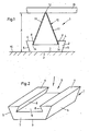
- the spacer 1 shown in FIGS. 1 to 3 essentially consists of a base body 2 made of cement-bound material, namely of fiber concrete.
- the base body 2 is preferably produced by extrusion or extrusion of a cross section corresponding to the cross section of the base body 2 from the cement-bound material (fiber concrete), which (profile) then in the not yet hardened state or in the already hardened state into the individual base bodies 2 is separated.
- the base body 2 has a cross section corresponding to an isosceles trapezoid, the one of the two parallel sides of this cross section being formed from the underside 3 and the other and longer of the two parallel sides being formed from the top side 4 of the base body 2.
- the two legs of the trapezoidal cross-section are formed by the two longitudinal sides 5 of the base body 2, wherein each longitudinal side 90 forms with the upper surface 4 form an angle smaller than o.
- a groove-shaped recess 6 is formed, which is open to this top 4 and to the two end faces 7 of the base body 2, which run at right angles to the bottom 3 and the top 4 in the embodiment shown.
- the recess 6 has a dovetail cross-section in the form that the side surfaces 8 extending in the direction of the longitudinal sides 5 of the recess 6 provided in the center of the upper side 4 and extending in the direction of the longitudinal sides 5 with the bottom surface 9 of this recess 6 make an angle smaller than Include 90 o , so that the width of the recess 6 increases from the top 4 towards the bottom surface 9. Due to the dovetail-shaped cross section, the recess 6 has an undercut on both of its longitudinal sides (in the region of the side surfaces 8).
- a support element 10 projecting above the upper side 4 of this base body is fastened to the base body.
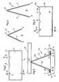
- the support element consists of a rectangular or square blank of sheet steel, which, at a V-shaped along a center line which runs parallel to two cutting edges or oblique roof-like profile with two an acute angle, ie an angle of less than 90 o confining legs 11 bent is.
- the two legs 11 each have the same length at an angle downwards from the transition region connecting these legs 11 or from the bending edge 12 connecting the legs 11.
- notches 13 are made in the material of the support element 10 and extend transversely to this longitudinal edge 12 and are open at the top.
- the bending of the V-shaped support element 10, the length of which in the spacer 1 is equal to or slightly less than the distance between the two end faces 7 of the base body 2, is carried out in such a way that the two legs 11 after the support element 10 has been bent at their free, edges 14 which extend over the entire length of the support element 10, run parallel to the longitudinal edge 12 and lie away from this longitudinal edge, are at a distance from one another which is somewhat larger than the width of the recess 6 or the distance between the two side surfaces 8 of this recess.
- the support element 10 can then be inserted with the edges 14 into the recess 6.
- the support element 10 After the insertion of the support element 10 into the recess 6, this rests with its legs 11 in the region of the edges 14 resiliently against the side surfaces 8 of the recess 6 and is thus resilient in the recess 6, that is to say it is held by a clamp fit.
- the flat material used for the production of the support element 10 is selected so that it has a sufficient spring action for the above-described clamping fit the support element 10 or its leg 11 ensures, this spring action is also supported by the notches 13 in the region of the upper longitudinal edge 12.
- the larger support element 10' (apart from the larger width of the legs 11) is designed in the same manner as that described above for the support element 10.
- a correspondingly smaller support element 10 or a correspondingly larger support element 10 ' is preferably attached to a base body 2 at the application site (construction site).
- the application site construction site
- preferably more than two different sizes are provided for the support element.
- the formwork or a plurality of spacers 1 with the underside 3 of their base bodies 2 are placed on the base 16 in a predetermined distribution.
- the reinforcing bars 15 can then be placed, preferably in the area of the notches 13, which then also slipping of the reinforcing bars 15 on the spacers or
- the V-shaped profile of the support elements 10 and 10 ensures that after placing the structural steels 15 on the spacers 1, the legs 11 of the support elements 10 and 10' in the sense of an even firmer connection with the respective base body 2 by Weight of the reinforcing bars 15 to be spread apart.
- the spacers 1 are embedded in the concrete, the base body 2 made of cement-bound material or fiber concrete forming an intimate connection with the concrete of the concrete component, i.e. not forming any foreign bodies in the concrete, and also ensuring that all metal or Steel parts, namely the support elements 10 and 10 'are embedded sufficiently deep in the concrete component produced.
- the trapezoidal cross section of the base body 2 improves the firm integration of this base body in the concrete.
- this cross-section also has the advantage that the respective base body 2, with the least possible material consumption, has a sufficient material volume in the area of the groove-shaped recess 6 where the greatest load on the base body occurs, namely.
- the spacer 1 by using the compared to the support element 10 or 10 'much heavier base body 2 (also due to the trapezoidal cross-sectional shape) has the advantage that the spacer 1 after placing the bottom 3 on the substrate 16 a has a very stable position and does not tip over. 5 to 7 show a spacer 1a, which differs from the spacer 1 of FIGS.
- the base body 2a of the spacer 1a instead of the dovetail-shaped recess 6 on the top 4 has a groove-shaped recess 6a, which also extends in the direction of the longitudinal sides 5 of the base body 2a in the middle of the top 4 of this base body, is open towards the top 4 and towards the two end faces 7 of the base body 2a.
- the recess 6a has on both of them, also in the direction of the long sides 5 extending side surfaces 8a each have a groove-shaped undercut 17.
- the spacer 1a also has the support element 10a, which is made in the same way as the support element 10 or 10 'by bending from a rectangular or square blank of flat material, preferably made of sheet steel, and a V-shaped profile with the two legs 11a adjoining one another over the upper longitudinal edge and enclosing an acute angle with one another.
- the two legs 11a are each angled outward in the area of the spacer 1a in their area remote from the longitudinal edge 12a, so that there are bends 18 extending over the entire length of the support element 10a, of which in the base body 2a or in the recess 6a used there, the support element 10a extends each bend 18 into an undercut 17 and is essentially parallel to the bottom surface 9a of the recess 6a.
- Each bend 18 has a width (distance of the edge 14a extending in the longitudinal direction of the support element 10a or the longitudinal edge 12a from the transition 19 to the respective leg 11a), which (width) is greater than the depth of the undercuts 17, so that in the base element 2a inserted contact element 10a just rest with the edges 14a against the surface of the undercut 17 running perpendicular to the top 4 or bottom 3.
- the notches 13 are again provided in the region of the upper longitudinal edge 12a.
- the support element is again available in different sizes, as shown in FIG. 7 in position a for the smaller contact element 10a and in position b there for the larger contact element 10a '.
- the advantages and the type of use of the spacer 1a are the same as those described above for the spacer 1, although it is ensured by the recess 6a with the undercuts 17 and by the bends 18 that even with very different sizes or Height of the support element 10a or 10a 'in relation on the attachment or mounting of this support element on the base body 2a each give the same optimal conditions, which is not guaranteed in this form for the spacer 1, since the angle formed between the legs 11 there with a very different size of the support element 10 or 10 'of the angle of inclination of the side faces 8 can deviate more. It is understood that more than two different size or height different support elements 10a and 10a 'can be provided for the spacer 1a, which can then be combined depending on the application with the base body 2a to the required spacer 1a.
- Fig. 8 shows in a similar representation as FIG. 4, a support element 10b, which can be used instead of the support element 10 or 10 'in the spacer 1 of FIGS. 1 to 3.
- the support element 10b which in turn is produced from a rectangular or square blank from flat material by bending, has a trapezoidal cross section in which the legs 11b are connected to one another via a yoke section 12b. The latter is then preferably again provided with the notches 13 and serves as a support for the reinforcing bars 15.
- a support element 10c is shown, which can be used for the spacer 1a and is provided in a manner similar to the support element 10a or 10a 'with the bends 18.
- the two legs 11c are connected to one another by a yoke section 12c, which preferably has the notches 13 and serves as a support surface for the reinforcing bars 15.
- a base body 2b is shown in FIGS. 10 and 11, which is produced in the same way as the base bodies 2 and 2a from cement-bound material or fiber concrete.
- the base body 2b together with the support element 10a, 10a 'or 10c can be combined to form a spacer and differs from the base body 2a essentially only by its outer cross-sectional shape, so that in FIGS. 10 and 11 in turn those elements which correspond in terms of their shape and function to the elements of the base body 2a, are designated by the same reference numerals as in FIG. 5.
- the base body 2b has on its top 4 in turn the recess 6a with the undercuts 17 provided on the two side surfaces 8a of this recess, into which the angled portions 18 of the respective support element 10a, 10a 'and 10c engage, in the same way as this has been described above for the spacer 1a.
- the base body 2b does not have a trapezoidal cross section, but an essentially rectangular cross section, so that the underside 3a of the base body 2b has a substantially greater width in the axial direction perpendicular to the longitudinal extent of the recess 6a than the underside 3 of the base body 2a. This also results in a larger contact surface for the base body 2b or for the corresponding spacer.
- a laterally open, laterally open and cross-sectionally V-shaped groove 20 is provided on each longitudinal side 5a .
- the base body 2b is chamfered at 21 at the transition region between the top 4 and the longitudinal sides 5a.
- a V-shaped recess for example, can also be provided in the center of the bottom 9a of the recess 6a, as indicated by the broken line 22, the recess 22, however, only extending in the area where the bends 18 of the Support element 10a, 10a 'and 10c not rest against the floor 9a.
- the side surfaces 8a lying above the undercuts 17 are designed to be slightly oblique in such a way that the mutual distance between these side surfaces 8a increases with increasing distance from the upper side 4. This facilitates the insertion of the respective support element 10a, 10a 'or 10c into the recess 6a.
- a support element 10d is shown as a further embodiment, which, like the support element 10c, has two legs 11d, each with an angle 18.
- the two legs 11d which are provided in the support element 10d essentially parallel to and at a distance from one another, that is to say not deviating from the legs 11c, are connected to one another by a yoke section 12d which is concave in its central region in a plan view of the support element 10d is curved in such a way that this results in a longitudinal extension of the support element 12d, ie In the direction perpendicular to the drawing plane of FIG.
- a clamp 24 made of resilient material, for example spring steel, is provided, which lies with its free end of two angled sections 24 'above the recess 23.
- the support element 10d is provided at the two bump-like transition areas 25 both in the legs 11d and in the yoke section 23 with recesses 26 which are open towards the top of the support element 10d and are perpendicular to the axis direction Longitudinal extension of the support element 10d, ie are congruently arranged in the axial direction of FIG. 13.
- These recesses 26, which extend into the respective leg 11d and into the adjoining part of the yoke section 12d, can then be used to hold a reinforcing steel 15, which is arranged perpendicular to the longitudinal extension of the support element 10d, as shown in FIG broken lines 15 'and is indicated in Fig.
- the clamp 24 is designed like a fork in such a way that it has a section 24 'on both sides of the recesses 26.
- the recesses 26 are produced in that two rectangular or square openings are made in the steel-sheet metal blank used for the production of the support element 10d, specifically before the bending of this blank into the support element 10d. It is understood that the recess 26 in the yoke section 12d is also continuous, i.e. can extend from a bump-like transition region 25 to the other bump-like transition region 25, so that only a rectangular or square opening then has to be introduced into the steel-sheet metal blank used for the production of the support element 10d.
- the support element 10d can also be designed without the bracket 24 and / or in such a way that the yoke section 12d does not have the trough-like recess 23, in the latter case the respective reinforcing steel 15 can in turn only be placed on the support element 10d transversely to the longitudinal direction thereof, namely in the recesses 26.
- the support element 10d can also be designed such that the legs 11d run divergingly, so that the support element 10d then either has a triangular profile corresponding to the support element 10a or a trapezoidal profile corresponding to the support element 10c.
- the support element 10d is suitable for use together with the base body 2a or for use together with the base body 2b, as indicated by broken lines in FIG. 12.
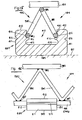
- the spacer 101 shown in FIGS. 15 and 16 essentially consists of a support element 102 which, in the embodiment shown, has a lattice-like structure and has three lattice bars 103-105 arranged parallel to one another and at a distance from one another.
- These bars 103-105 which are each formed from a length of structural steel and extend over the entire length of the spacer 101, are provided spatially with respect to one another in such a way that these bars 103-105 are viewed from the front of the spacer 101 or in cross section through the spacer 101 form the corner points of an isosceles triangle, the two sides of the same length of this triangle extending between the bars 103 and 105 or 104 and 105 and the shorter side of this triangle between the bars 103 and 104.
- the lattice bars 103 and 105 or 104 and 105 are also connected to one another by transverse connections 106 made of structural steel.
- these are the grids rods 103 and 105 or 104 and 105 connecting cross connections each have lengths of a zigzag-shaped structural steel which also extends over the entire length of the spacer 101 and in the region of its tips at 107 with the lattice rod 105 or with the lattice rod 103 or 104 is welded.
- cross connections 106 can also be formed in each case from individual or separate lengths of structural steel.
- the spacer 101 also has a plurality of base bodies 108 made of cement-bound material, namely of fiber concrete.
- the base bodies 108 are preferably produced by extruding or extruding a profile from this cement-bonded material (fiber concrete) corresponding in cross section to the cross section of the base bodies 108. This profile is then cut into the individual base bodies 108 in the not yet hardened state or in the already hardened state.
- each base body 108 is approximately cuboid, ie it has a substantially rectangular cross section in a cross-sectional plane perpendicular to the longitudinal extent of the spacer 1.
- Each base body thus has an underside 109, an essentially parallel top side 110, two longitudinal sides 111 perpendicular to the underside 109 and to the top side 110, and two end faces 112, each essentially perpendicular to the underside 109, the top side 110 as well as to the two long sides 111.
- a groove-shaped recess 113 is formed in each base body 108, which is open to the top 110 and to the two end faces 112.
- This recess 113 has a rectangular cross section in the embodiment shown and is in itself Longitudinal direction of the base body 108 and thus perpendicular to the end faces 112 and parallel to the long sides 111 extending side surfaces 114 each with two in the direction perpendicular to the bottom 109 or top 110 overlapping to the interior of the recess 113 open groove-like recesses 115 and 116, respectively also extend in the longitudinal direction of the base body 108 over the entire length of this base body, ie from one end face 112 to the other end face 112.
- the recess 115 on one side surface 114 is opposite a corresponding recess 115 on the other end surface 114, in each case at the same distance from the underside 109.
- the recess 116 on one side surface 114 is opposite the recess 116 on the other side surface 114.
- the recesses 115 and 116 are designed such that they can each receive a lattice rod 103 or 104, in the form that in the area of these recesses 115 and 116 a support surface for the lattice rods 103 and 104 is formed and the remaining part of the support element 102, in particular also the lattice rod 105 protrudes over the upper side of the base body 108, as shown in FIG. 15.
- base bodies 108 are provided on the support element 102 in the above-described manner at predetermined intervals and in each case preferably between two transverse connections successive in the longitudinal direction of the support element 102.
- the spacer 101 can thus be placed with the base bodies 108 on top of, for example, a horizontal formwork wall 111 or another base, in such a way that all of the base bodies 108 stand with their underside 109 on the formwork wall 117 or the base and thus the one made of structural steel Support element 102 are held by the base body 108 at a greater distance from this formwork wall or the subsurface.
- the spacer 101 is the bearing surface for the concrete reinforcement formed by reinforcing steel, as is indicated in FIG. 15 for the reinforcing steel 118.
- the effective height of the spacer 101 ie the distance of the support surface formed by the grating bar 115 from the underside 109 of the base body 108 can be varied by using either the cutouts 115 for receiving or arranging the grating bars 103 and 105 As shown in FIG. 15, or if the height of the spacer 101 is lower, the cutouts 116 are used for this.
- the concrete component to be produced is concreted in the usual way, whereby after the concrete has hardened, the base bodies made of cement-bound material are embedded in the concrete and do not represent any foreign bodies and for all iron - or steel parts through the base body 108 a sufficiently deep embedding in the concrete is guaranteed.
- the embedding of the base body 108 in the concrete is further improved in that these base bodies 108 are each provided with a longitudinal groove 119 on their long sides 111.
- the base bodies 108 have a dovetail-shaped cross section such that the top 110 of each base body 108 has a greater width and / or length than the bottom 109.
- the spacer 101 is made shorter, it is also possible for the spacer 101 to have only a single base body 108, which then extends over the entire or almost the entire length of the support element 102.
- the spacer 101 can also consist of two or more than two support elements 102 which connect to one another in the longitudinal direction of the spacer 101.
- Two successive support elements 102 are then attached to a common base body 108 and are connected to one another via this.
- the respective support element 102 can furthermore preferably be designed in such a way that the bars 103 and 104 are also connected to one another by cross connections 106, and then preferably in the same manner as that for the cross connections 106 between the bars 103 and 105 or 104 and 105 has been described.
- the spacer 101a shown in FIGS. 17 and 18 essentially consists of a support element 102a, which is formed by a length of a plastic profile.
- This plastic profile has a U-shaped cross section with two legs 120 extending over the entire length of the support element 102a and with a plate-shaped yoke section 121 connecting these legs 120, from one surface side of which forms the underside of the yoke section 121, which is parallel to and spaced apart from each other legs stand substantially vertically.
- the yoke section 121 also extends over the entire length of the support element 102a.
- the legs 120 are each provided with a bend 122 at their free end remote from the yoke section 121, these bends running obliquely outwards in such a way that the distance between the two legs 120 and the bends 122 in their area increases with increasing distance from the yoke section 121.
- At least the yoke section 121 is provided with a plurality of window-like openings 123.
- each base body 108a is fastened to two base bodies 108a, each base body 108a being located in the region of one end of the support element 102a.
- each base body with a dovetail cross-section has on its top 124 a recess 125 which is open towards this top side and towards the two end faces of the base body 108a and which has a dovetail cross-section such that the width the recess 125 increases with increasing distance from the top 124, so that the recess 125 forms undercuts on both sides.
- the angled portions 122 102a engages the support element in the recesses 125 of the base body 108a in such a manner that each angled portion 122 a slant to the bottom of the recess 125 extending, ie with said bottom an angle less than o enclosing side surface 126 immediately adjacent 90 is or rests against this side surface 126 and the legs 120 project with their greater width over the top 124 of the base body 108a.
- the yoke section 121 with its upper side facing away from the legs 120, forms the bearing surface of the spacer 101a for the structural steels 118 which constitute the test.
- the openings 123 ensure that concrete is also poured into the space delimited by the legs 120 and the yoke section 121 when the concrete component is concreted can penetrate.
Landscapes
- Engineering & Computer Science (AREA)
- Architecture (AREA)
- Civil Engineering (AREA)
- Structural Engineering (AREA)
- Reinforcement Elements For Buildings (AREA)
Applications Claiming Priority (8)
| Application Number | Priority Date | Filing Date | Title |
|---|---|---|---|
| DE8809675 | 1988-07-29 | ||
| DE8809675U | 1988-07-29 | ||
| DE8809931U | 1988-08-04 | ||
| DE8809931U DE8809931U1 (de) | 1988-07-29 | 1988-08-04 | Abstandshalter für Betonarmierungen |
| DE8814290U | 1988-11-15 | ||
| DE8814290 | 1988-11-15 | ||
| DE8814834U | 1988-11-29 | ||
| DE8814834U DE8814834U1 (de) | 1988-11-15 | 1988-11-29 | Abstandshalter für Betonarmierungen |
Publications (1)
| Publication Number | Publication Date |
|---|---|
| EP0353560A1 true EP0353560A1 (fr) | 1990-02-07 |
Family
ID=27436333
Family Applications (1)
| Application Number | Title | Priority Date | Filing Date |
|---|---|---|---|
| EP89113423A Withdrawn EP0353560A1 (fr) | 1988-07-29 | 1989-07-21 | Espaceur pour armatures de béton |
Country Status (1)
| Country | Link |
|---|---|
| EP (1) | EP0353560A1 (fr) |
Cited By (6)
| Publication number | Priority date | Publication date | Assignee | Title |
|---|---|---|---|---|
| AT404957B (de) * | 1993-11-19 | 1999-04-26 | Avi Alpenlaendische Vered | Bewehrungselement |
| DE102015001222A1 (de) | 2014-02-07 | 2015-08-13 | Alois Kappelsberger | Abstandshalter für eine Bewehrung im Stahlbetonbau |
| WO2017201577A1 (fr) * | 2016-05-25 | 2017-11-30 | Geoff Wyett | Raccord de renfort-bardage de coffrage perdu et son procédé d'utilisation |
| CN108158537A (zh) * | 2018-02-28 | 2018-06-15 | 佛山市顺德区美的洗涤电器制造有限公司 | 防抱夹结构以及洗碗机 |
| FR3127772A1 (fr) * | 2021-10-04 | 2023-04-07 | Isoltop | Procédé de fabrication d’une poutrelle et son installation. |
| US11713577B2 (en) | 2021-06-17 | 2023-08-01 | Dayton Superior Corporation | Reinforcement positioner with clip |
Citations (9)
| Publication number | Priority date | Publication date | Assignee | Title |
|---|---|---|---|---|
| CH436651A (de) * | 1964-11-21 | 1967-05-31 | Baustahlgewebe Gmbh | Aus bewehrtem Beton bestehender prismatischer Körper zur Auflagerung der unteren Bewehrung von Betonbauteilen |
| DE2062960A1 (de) * | 1970-12-21 | 1972-07-06 | Fleischmann, Fritz, 8000 München | Korbartiger Abstandshalter für Betonbewehrungen |
| DE7329839U (de) * | 1973-11-22 | Hoff W | Abstandhalter für Bewehrungselemente von Betonbauwerken | |
| US4080770A (en) * | 1974-08-06 | 1978-03-28 | Sandor Vigh | High chair spacer |
| FR2370140A1 (fr) * | 1976-11-09 | 1978-06-02 | Sibel Ste Fse | Dispositif pour la construction de planchers en beton arme a nervure sur semelles de bois et entrevous |
| DE2842426A1 (de) * | 1978-09-29 | 1980-04-17 | Zirks Werner Richard | Abstandhalter |
| DE3021141A1 (de) * | 1980-06-04 | 1981-12-10 | J. Lehde Gmbh, 4770 Soest | Abstandshalter insbesondere fuer mehrlagige bewehrungen |
| FR2570413A1 (fr) * | 1984-09-20 | 1986-03-21 | Jungk Ernst | Poutre de plancher armee |
| EP0182935A1 (fr) * | 1984-11-29 | 1986-06-04 | Betomax Kunststoff- und Metallwarenfabrik GmbH. & Co. KG. | Appui d'écartement pour armatures de construction en béton ou similaire |
-
1989
- 1989-07-21 EP EP89113423A patent/EP0353560A1/fr not_active Withdrawn
Patent Citations (9)
| Publication number | Priority date | Publication date | Assignee | Title |
|---|---|---|---|---|
| DE7329839U (de) * | 1973-11-22 | Hoff W | Abstandhalter für Bewehrungselemente von Betonbauwerken | |
| CH436651A (de) * | 1964-11-21 | 1967-05-31 | Baustahlgewebe Gmbh | Aus bewehrtem Beton bestehender prismatischer Körper zur Auflagerung der unteren Bewehrung von Betonbauteilen |
| DE2062960A1 (de) * | 1970-12-21 | 1972-07-06 | Fleischmann, Fritz, 8000 München | Korbartiger Abstandshalter für Betonbewehrungen |
| US4080770A (en) * | 1974-08-06 | 1978-03-28 | Sandor Vigh | High chair spacer |
| FR2370140A1 (fr) * | 1976-11-09 | 1978-06-02 | Sibel Ste Fse | Dispositif pour la construction de planchers en beton arme a nervure sur semelles de bois et entrevous |
| DE2842426A1 (de) * | 1978-09-29 | 1980-04-17 | Zirks Werner Richard | Abstandhalter |
| DE3021141A1 (de) * | 1980-06-04 | 1981-12-10 | J. Lehde Gmbh, 4770 Soest | Abstandshalter insbesondere fuer mehrlagige bewehrungen |
| FR2570413A1 (fr) * | 1984-09-20 | 1986-03-21 | Jungk Ernst | Poutre de plancher armee |
| EP0182935A1 (fr) * | 1984-11-29 | 1986-06-04 | Betomax Kunststoff- und Metallwarenfabrik GmbH. & Co. KG. | Appui d'écartement pour armatures de construction en béton ou similaire |
Cited By (7)
| Publication number | Priority date | Publication date | Assignee | Title |
|---|---|---|---|---|
| AT404957B (de) * | 1993-11-19 | 1999-04-26 | Avi Alpenlaendische Vered | Bewehrungselement |
| DE102015001222A1 (de) | 2014-02-07 | 2015-08-13 | Alois Kappelsberger | Abstandshalter für eine Bewehrung im Stahlbetonbau |
| WO2017201577A1 (fr) * | 2016-05-25 | 2017-11-30 | Geoff Wyett | Raccord de renfort-bardage de coffrage perdu et son procédé d'utilisation |
| CN108158537A (zh) * | 2018-02-28 | 2018-06-15 | 佛山市顺德区美的洗涤电器制造有限公司 | 防抱夹结构以及洗碗机 |
| CN108158537B (zh) * | 2018-02-28 | 2023-07-07 | 佛山市顺德区美的洗涤电器制造有限公司 | 防抱夹结构以及洗碗机 |
| US11713577B2 (en) | 2021-06-17 | 2023-08-01 | Dayton Superior Corporation | Reinforcement positioner with clip |
| FR3127772A1 (fr) * | 2021-10-04 | 2023-04-07 | Isoltop | Procédé de fabrication d’une poutrelle et son installation. |
Similar Documents
| Publication | Publication Date | Title |
|---|---|---|
| EP0131841B1 (fr) | Ancrage pour un panneau stratifié | |
| EP0744508B1 (fr) | Dispositif pour former une armature de cisaillement pour dalles plates | |
| EP0495334B1 (fr) | Armature de cisaillement pour des plafonds plats | |
| EP0388692B1 (fr) | Elément isolé de raccordement pour plaque en porte-à-faux | |
| EP0927796B1 (fr) | Panneau et système de coffrage | |
| EP0341507A2 (fr) | Coffrage | |
| EP0299226B1 (fr) | Coffrage pour la réalisation d'éléments de construction en béton | |
| DE4342253A1 (de) | Elemente zum Verstärken, Haltern und Verbinden von Stahlstäben für armierten Beton | |
| DE2206973A1 (de) | Raeumliches bauelement zur bildung von trag- und stuetzwerken aller art | |
| EP0353560A1 (fr) | Espaceur pour armatures de béton | |
| EP3921490B1 (fr) | Ensemble comprenant un système de montage et un dispositif d'ancrage et un procédé de montage d'un ensemble | |
| LU81759A1 (fr) | Laermschutzwand | |
| CH651095A5 (de) | Bewehrungselement zur uebertragung von querkraeften in plattenartigen traggliedern, z.b. flachdecken. | |
| CH642131A5 (en) | Connection cage for reinforcing reinforced-concrete structures and the use thereof | |
| DE3434531A1 (de) | Bewehrter deckentraeger | |
| DE29903737U1 (de) | Bauelement zur Schubbewehrung | |
| CH686686A5 (de) | Stuetzenkopfverstaerkung. | |
| DE10014977A1 (de) | Profilschiene | |
| EP1932978B1 (fr) | Elément d'armature pour l'absorption de forces dans des plaques de béton dans la zone d'éléments d'appui | |
| WO1999007958A1 (fr) | Espaceur | |
| DE29808491U1 (de) | Bewehrungselement für Schubbewehrungen | |
| EP2175079B1 (fr) | Procédé de formation d'une armature d'angle résistante à la flexion pour la construction en béton armé, élément d'armature et armature d'angle résistante à la flexion | |
| DE10001595A1 (de) | Bewehrung für Stahlbetondecken | |
| DE3730679C2 (fr) | ||
| DE4228968A1 (de) | Balken, verfahren zu dessen herstellung, verfahren und vorrichtung zum verbinden solcher balken |
Legal Events
| Date | Code | Title | Description |
|---|---|---|---|
| PUAI | Public reference made under article 153(3) epc to a published international application that has entered the european phase |
Free format text: ORIGINAL CODE: 0009012 |
|
| AK | Designated contracting states |
Kind code of ref document: A1 Designated state(s): AT BE CH DE ES FR GB GR IT LI LU NL SE |
|
| STAA | Information on the status of an ep patent application or granted ep patent |
Free format text: STATUS: THE APPLICATION IS DEEMED TO BE WITHDRAWN |
|
| 18D | Application deemed to be withdrawn |
Effective date: 19900808 |