EP0353575A1 - Dispositif d'arrêt pour un ruban de fibres - Google Patents
Dispositif d'arrêt pour un ruban de fibres Download PDFInfo
- Publication number
- EP0353575A1 EP0353575A1 EP89113523A EP89113523A EP0353575A1 EP 0353575 A1 EP0353575 A1 EP 0353575A1 EP 89113523 A EP89113523 A EP 89113523A EP 89113523 A EP89113523 A EP 89113523A EP 0353575 A1 EP0353575 A1 EP 0353575A1
- Authority
- EP
- European Patent Office
- Prior art keywords
- roller
- rollers
- fiber
- pair
- sliver
- Prior art date
- Legal status (The legal status is an assumption and is not a legal conclusion. Google has not performed a legal analysis and makes no representation as to the accuracy of the status listed.)
- Granted
Links
Images


Classifications
-
- D—TEXTILES; PAPER
- D01—NATURAL OR MAN-MADE THREADS OR FIBRES; SPINNING
- D01H—SPINNING OR TWISTING
- D01H13/00—Other common constructional features, details or accessories
- D01H13/14—Warning or safety devices, e.g. automatic fault detectors, stop motions ; Monitoring the entanglement of slivers in drafting arrangements
- D01H13/16—Warning or safety devices, e.g. automatic fault detectors, stop motions ; Monitoring the entanglement of slivers in drafting arrangements responsive to reduction in material tension, failure of supply, or breakage, of material
- D01H13/18—Warning or safety devices, e.g. automatic fault detectors, stop motions ; Monitoring the entanglement of slivers in drafting arrangements responsive to reduction in material tension, failure of supply, or breakage, of material stopping supply only
- D01H13/188—Warning or safety devices, e.g. automatic fault detectors, stop motions ; Monitoring the entanglement of slivers in drafting arrangements responsive to reduction in material tension, failure of supply, or breakage, of material stopping supply only by cutting or clamping yarns or rovings
Definitions
- the invention relates to a match stop device for use in combination with the drafting system of a spinning machine e.g. a ring spinning machine or jet spinning machine.
- the fiber material to be spun in the individual spinning position is normally delivered to this spinning position via a drafting system, the drafting system comprising a plurality of pairs of rollers.
- the fiber material template can be present in the form of an untwisted band, for example a stretch band, or in the form of a slightly twisted roving (for example from a flyer).
- fuse indicates an elongated structure of fiber material, wel ches serves as a template for a spinning machine, regardless of whether this template is provided with a support twist or not.
- the fiber feed at this spinning position is advantageously interrupted before the last pair of rollers of the drafting system (called exit, export or delivery roller pair) in order to reduce the loss of material and the risk of winding around a delivery roller.
- exit, export or delivery roller pair the last pair of rollers of the drafting system
- the invention provides a drafting system with an input roller pair available for each spinning position, the one roller of the pair being set in operation by a drive about its own longitudinal axis and the revolutions of this first roller by contact between the rollers of the pair to the second (pressure -) roller are transferred.
- the second roller is only assigned to the relevant spinning position, while the first roller can also be present as a single roller per spinning position or in the form of a continuous cylinder that extends over several spinning positions.
- the invention also provides for each spinning position a fiber guiding element for removing contact between the rollers of the pair of input rollers of this spinning position.
- the pressure roller can be lifted off the driven roller to remove the contact.
- the invention is characterized in that the guide element is arranged for each spinning position in such a way that the force lifting off the pressure rollers is exerted against the surface of the roller, and the fuse is thereby clamped.
- the fiber guiding element is (e.g. a funnel or a thread condenser) and guides the fiber stream in normal operation and is pressed against the pressure roller of the pair of input rollers when the thread breaks, thereby lifting the contact between the rollers and at the same time holding the fuse against the outer surface of the pressure roller.
- Such a fiber guide element is preferably arranged on the input side of the pair of input rollers.
- the fiber guide element is preferably movable between a normal position and an operative position, the fiber guide element allowing contact between the input rollers in its normal position and canceling it in its operative position.
- the fiber guide element performs a rotary movement between the normal position and the operative position.
- the sliver clamping point ie the point at which the sliver is clamped between the fiber guide element and the pressure roller after the contact between the drafting rollers has been removed, is normally ge slightly offset from the normal nip line of the input roller pair around the circumference of the pressure roller.
- the pressure roller is moved to remove contact with the input roller on a path which is a substantially straight extension of a pressure roller radius running through the nip.
- the fiber guide element can be connected via a signal transmission system to a thread monitor assigned to the appropriate spinning position, so that in normal operation the switching of the fiber guide element is triggered by the thread monitor detecting a broken thread in the spinning position.
- an actuatable means can be provided to switch off the effect of the thread monitor when starting the machine if there is no thread in the spinning position at this time.
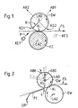
- the input cylinder EZ and the pressure roller DW form the input roller pair of a drafting system, not shown, on a spinning machine, not shown, for example. a ring spinning machine or a jet spinning machine.
- the input cylinder EZ extends over several spinning positions (possibly over an entire machine side, i.e. it is in the form of a so-called continuous cylinder).
- the printing roller DW is assigned to a single spinning position (not shown).
- the pressure roller DW is pressed against the input cylinder EZ in order to keep the jacket surfaces of the roller DW and the cylinder EZ in contact with one another along the clamping line KL.
- the clamping line KL preferably runs parallel to the longitudinal axis LAD of the printing roller DW and the longitudinal axis LAZ of the input cylinder EZ.
- a suitable drive causes the cylinder EZ (according to FIG. 1) to rotate clockwise about its own longitudinal axis LAZ.
- the contact between the printing roller DW and the input cylinder EZ transfers the revolutions of the cylinder to the printing roller, so that the latter (according to FIG. 1) is rotated counterclockwise around its own longitudinal axis LAD.
- a fuse not particularly indicated
- the pressure roller DW remains in the position shown in order to pull the material to be spun from the template, not shown, into the drafting system.
- the fiber feed should be interrupted, as close as possible to the pair of feed rollers. This invention enables such an interruption in a particularly simple way.
- a clamping element KE1 is moved in the direction of arrow P from a waiting position against the printing roller DW in order to form a clamping point KS by contact with the outer surface of the printing roller DW.
- the waiting position of the element KE1 is on the opposite side of the fiber stream FS from the pressure roller DW.
- the fiber stream is initially deflected slightly and then pinched off by the contact between the element KE1 and the pressure roller DW.
- the pressure roller DW is slightly lifted from the input cylinder EZ. Since the printing roller is no longer driven by the input cylinder EZ and at the same time is braked by the clamping element KE1, the printing roller stops immediately.
- the fiber flow FS continues to flow downstream from the clamping point KS1.
- the fibers thus supplied by the drafting system must be picked up and taken away by a suitable suction device (not shown).
- the fibers held at the clamping point KS1 remain ready for re-spinning.
- the clamping element KS1 can be moved back into the waiting position, the pressure roller DW being brought back into its operating position, ie in contact with the feed cylinder EZ, by the support arrangement.
- the nip KS1 is, as already mentioned, on the input side of the pair of insertion rollers, but this is not essential to the invention.
- a clamping element KE2 could be arranged on the output side of the pair of feed rollers in order to form a corresponding clamping point KS2 in the diverging space of this pair of rollers.
- the longitudinal axis LAD of the printing roller DW would preferably be moved along the web AB2 between the operating position and the raised position in order to remove the contact between the printing roller and the input cylinder EZ.
- the alternative solution on the input side of the pair of input rollers will normally be preferred.
- the pressure roller DW works together with a driven feed roller EW which is individually assigned to the corresponding spinning position (ie does not extend over several spinning positions).
- the fiber stream FS is guided from the template (not shown) via a guide element FE into the clamping line KL of the pair of feed rollers.
- the guide element FE is pivotally mounted about a pivot point DP and can be pivoted about the pivot point DP from a guide position (shown in FIG. 2) to an intermediate position (not shown) by a suitable means (not shown). In the latter position, an edge L on the front end of the guide element is in contact with the Print roller DW to form the nip KS.
- the printing roller DW is then lifted off the roller EW, the longitudinal axis LAD of the printing roller being able to follow either a straight path ABG or a curved path ABK.
- the clamping point KS is slightly offset in relation to the clamping line KL in the circumferential direction of the pressure roller DW, so that the fibers clamped at the point KS either lie in the clamping line KL when the pressure roller DW moves back or through the Input roller EW can be quickly fed back into the clamping line KL.
- the longitudinal axis LAD of the pressure roller is no longer arranged (as in FIG. 1) perpendicularly above the longitudinal axis LAZ of the input roller EW, but is offset in the direction of the fiber upstream to give the pressure roller a slight "overhang" with respect to the input roller To give EW.
- FIGS. 3 to 5 Such an arrangement is also shown in FIGS. 3 to 5.
- Figure 3 shows the feed roller pair EP, the middle roller pair MP and the delivery roller pair LP of a two-zone drafting system.
- the fiber material supplied by the drafting system is delivered to a spinning position SP, which is only indicated schematically, and there to a yarn G (FIG. 4) by working elements of the spinning position, not shown (for example by the spindle-ring rotor combination of a ring spinning machine or the suitable nozzle arrangement of a nozzle spinning machine or by combining a fiber collection device together with a mechanical false twister in an OE false twist machine).
- the fiber material to be spun is put into operation in the input rollers couple of EP passed through the guide channel 10 of a condenser K.
- this material is drawn into the drafting system from a template (not shown) (for example a spool or a can) through the pair of input rollers EP.
- the condenser K is rotatably mounted on a pin 12.
- the condenser K is equipped with a cantilever 14 which, at its end remote from the pin 12, cooperates with an actuating device BV described below.
- the device BV comprises a chamber 18 carried by the arm 14 and containing a piston 16.
- the piston 16 is connected via a piston rod 20 to a stationary part 22 of the machine frame (not shown in more detail).
- a compressed air line 24 opens into the end of the chamber 18 remote from the part 22.
- the arm (lever arm) 14 is pivoted counterclockwise around the pin 12 according to FIG. 3 to bring the output of the condenser K into contact with the pressure roller DW of the input roller pair EP.
- the compressed air works against a prestress exerted by a compression spring 26.
- the spring 26 is located between the chamber 18 and another stationary part 22A of the frame.
- the thread monitor FW triggers the supply of compressed air from a suitable source Q via the line 24 into the chamber 18 via a signal line 28 and via a compressed air valve M, which triggers the pivoting movement of the condenser K. .
- the drafting system temporarily delivers fiber material. This material is carried away by a suction AS arranged on the delivery roller pair LP. After the formation of the clamping point KS and the lifting of the pressure roller DW, the new introduction of fiber material from the template into the drafting system is interrupted. The material already present in the drafting system is passed on from the center roller pair MP and the delivery roller pair LP to the suction AS. The fibers held at the clamping point KS (FIG. 5), however, cannot participate in this fiber stream FS, so that the fiber stream is interrupted in the draft zone between the input roller pair EP and the middle roller pair MP. The fibers F remain "threaded" with the pair of input rollers EP.
- the valve M is readjusted in order to interrupt the compressed air supply from the source Q to the line 24 and to vent the chamber 18 via the line 24 and a line 32.
- This enables the return of the lever arm 14 and the condenser K into the operating position (FIGS. 3 and 4) under the biasing force exerted by the compression spring 26.
- the clamping line KL is formed again by restoring the contact between the pressure roller DW and the input roller EW and almost simultaneously the previously held fibers F are released again by the removal of the clamping point KS, which causes the new introduction of fiber material from the template into the drafting system to restore the fiber stream FS.
- the arrangement is accordingly self-threading.
- the vacuum at the suction AS can be simultaneously be interrupted with the new entry of the fiber feed so that the newly delivered fibers are now delivered to the provided spinning position SP.
- the suction AS can be connected again to a vacuum source, not shown, if the thread monitor FW detects a new thread break.
- the previously mentioned signal line 28 comprises a switch 34 which can be actuated by a push button D, a switch 36 which can be actuated by the thread monitor FW and a coil 38 which sets the valve M.
- the coil 38 therefore actuates the solenoid valve M so that compressed air from the source Q is conducted into the chamber 18. Accordingly, the condenser K is immediately moved from the operating position (FIG. 3) to the operative position (FIG. 5) in order to lift the pressure roller DW from the insertion roller EW and to clamp the fibers F which are still threaded with these rollers.
- the state of the main switch is shown on the top row of the signal diagram in FIG. 6, the state of the push button D on the second top row, the state of the thread monitor FW on the third top row and the state of the chamber 18 on the bottom row.
- the thread monitor FW determines the presence of this yarn G and opens the switch 36 (in FIG. 6, time T3). Shortly afterwards (at point T4) the push button D can be released again (e.g. by a suitable time relay, not shown) in order to close the switch 34 (FIG. 4).
- the overall arrangement has now reached the normal operating state and is ready to react to a possible thread break (in FIG. 6, time T5) with the opening of the switch 36 by the thread monitor FW.
- the starting process can be triggered again by actuating the push button D (in FIG. 6, time T6). Because the process when starting (after a thread break) corresponds exactly to the process of re-spinning (after the machine has been shut down), the process already described for re-spinning will not be repeated.
- the movable clamping element is formed as a fiber guide element (preferably as a sliver condenser), but this is not essential to the invention. It is also not necessary that the movement of the clamping element from its waiting position (in the preferred variant from the operating position of the condenser) into the operative position (clamping the fuse) is carried out by a pivoting movement. The same effect could be achieved by a linear movement of the clamping element.
- the preferred variant is particularly advantageous over the arrangement described in DOS 2952533, in which the number of work elements and the work paths are kept small, which enables a space-saving and simple arrangement.
- this invention achieves the advantage that the formation of the nip and the removal of contact between the insertion rollers occurs approximately simultaneously. This ensures that the separation of the fiber stream takes place after the formation (downstream of the) clamping point. However, since the clamping point KS is formed just in the vicinity of the clamping line KL, the retained fibers remain ready to start the sliver insertion.
- the pressure roller DW can be formed as a double roller unit, the rollers of one unit being assigned to respective adjacent spinning positions. There this arrangement for ring spinning is well known, it will not be explained here.
- the clamping forces exerted on the lateral surface of the pressure roller are also used to lift the pressure roller and thereby to remove contact between the rollers of the pair of input rollers.
- the clamping and lifting element counteracts a "grinding" (tangential) movement over the pressure roller (and the fuse) - both when lifting off and when resetting the pressure roller. An attempt is made to move the clamping element up to the normal clamping line of the pair of inlet rollers.
- the fuse is not subjected to any rubbing movement.
- the clamping element moves for clamping / lifting or for releasing / resetting in an approximately radial direction with respect to the pressure roller.
- the nip is slightly offset from the normal nip line in the circumferential direction of the pressure roller and is therefore accessible, despite a relatively short path of movement of the nip element, without substantial tangential movement of the nip element.
- a condenser enclosing the fuse preferably opens against the pressure roller in order to simplify the formation of a clamping edge on the condenser.
- the fiber guide as a clamping element, the latter can be in its "waiting" (fiber-guiding) position particularly close to the pressure roller, and thus to the nip.
Landscapes
- Engineering & Computer Science (AREA)
- Mechanical Engineering (AREA)
- Textile Engineering (AREA)
- Spinning Or Twisting Of Yarns (AREA)
- Forwarding And Storing Of Filamentary Material (AREA)
Applications Claiming Priority (2)
| Application Number | Priority Date | Filing Date | Title |
|---|---|---|---|
| CH295788 | 1988-08-04 | ||
| CH2957/88 | 1988-08-04 |
Publications (2)
| Publication Number | Publication Date |
|---|---|
| EP0353575A1 true EP0353575A1 (fr) | 1990-02-07 |
| EP0353575B1 EP0353575B1 (fr) | 1995-03-08 |
Family
ID=4245443
Family Applications (1)
| Application Number | Title | Priority Date | Filing Date |
|---|---|---|---|
| EP89113523A Expired - Lifetime EP0353575B1 (fr) | 1988-08-04 | 1989-07-22 | Dispositif d'arrêt pour un ruban de fibres |
Country Status (4)
| Country | Link |
|---|---|
| US (1) | US4972667A (fr) |
| EP (1) | EP0353575B1 (fr) |
| JP (1) | JP2865720B2 (fr) |
| DE (1) | DE58909079D1 (fr) |
Families Citing this family (3)
| Publication number | Priority date | Publication date | Assignee | Title |
|---|---|---|---|---|
| US5235800A (en) * | 1989-09-13 | 1993-08-17 | Maschinenfabrik Rieter Ag | Method and apparatus for initiation of servicing operations in a textile spinning machine |
| US5566539A (en) * | 1990-07-20 | 1996-10-22 | Binder; Rolf | Method and apparatus for repairing a yarn breakage in a pair of spinning units |
| CH685123A5 (de) * | 1991-11-21 | 1995-03-31 | Rieter Ag Maschf | Streckwerk für eine Feinspinnmaschine, insbesondere Düsenspinnmaschine. |
Citations (9)
| Publication number | Priority date | Publication date | Assignee | Title |
|---|---|---|---|---|
| GB1438276A (en) * | 1972-07-03 | 1976-06-03 | Mackie & Sons Ltd J | Textile machines |
| GB2090618A (en) * | 1981-01-02 | 1982-07-14 | Skf Kugellagerfabriken Gmbh | Sliver stop motion in the drafting heads of spinning machines |
| DE3048481A1 (de) * | 1980-12-22 | 1982-07-22 | Spindelfabrik Süßen, Schurr, Stahlecker & Grill GmbH, 7334 Süßen | "vorrichtung zum unterbrechen der zufuhr eines vorgarns an streckwerken" |
| DE3119408A1 (de) * | 1980-12-22 | 1982-12-09 | Spindelfabrik Süßen, Schurr, Stahlecker & Grill GmbH, 7334 Süßen | Vorrichtung zum unterbrechen der zufuhr eines vorgarns an streckwerken einer spinnmaschine |
| DE3218660C1 (de) * | 1981-01-02 | 1983-08-25 | Skf Kugellagerfabriken Gmbh, 8720 Schweinfurt | Luntensperrvorrichtung an Spinnmaschinen-Streckwerken |
| DE3226151A1 (de) * | 1982-07-13 | 1984-01-19 | Skf Kugellagerfabriken Gmbh, 8720 Schweinfurt | Luntensperrvorrichtung an spinnmaschinen-streckwerken |
| DE3318925A1 (de) * | 1983-05-25 | 1984-11-29 | Stahlecker, Fritz, 7347 Bad Überkingen | Vorrichtung zum unterbrechen der zufuhr eines vorgarns an einem streckwerk |
| DE3327966A1 (de) * | 1983-08-03 | 1985-02-21 | Fritz 7347 Bad Überkingen Stahlecker | Streckwerk fuer spinnereimaschinen |
| DE3532541A1 (de) * | 1985-09-12 | 1987-03-19 | Skf Textilmasch Komponenten | Luntensperrvorrichtung an spinnmaschinen-streckwerken |
Family Cites Families (8)
| Publication number | Priority date | Publication date | Assignee | Title |
|---|---|---|---|---|
| JPS4927788U (fr) * | 1972-06-09 | 1974-03-09 | ||
| DE2952533A1 (de) * | 1979-12-28 | 1981-07-02 | Zinser Textilmaschinen Gmbh, 7333 Ebersbach | Spinnmaschine |
| DE3100049C2 (de) * | 1981-01-02 | 1983-11-10 | Skf Kugellagerfabriken Gmbh, 8720 Schweinfurt | Luntensperrvorrichtung an Spinnmaschinen-Streckwerken |
| DE3145798C2 (de) * | 1981-11-19 | 1983-11-03 | Skf Kugellagerfabriken Gmbh, 8720 Schweinfurt | Luntensperrvorrichtung an Spinnmaschinen-Streckwerken |
| JPS5835669U (ja) * | 1981-09-01 | 1983-03-08 | 石川島播磨重工業株式会社 | デイ−ゼル機関の燃料噴射ポンプ |
| CH658474A5 (de) * | 1982-05-18 | 1986-11-14 | Skf Kugellagerfabriken Gmbh | Luntensperrvorrichtung an spinnmaschinen-streckwerken. |
| DE3406397C1 (de) * | 1984-02-22 | 1985-07-11 | SKF GmbH, 8720 Schweinfurt | Luntensperrvorrichtung an Spinnmaschinen-Streckwerken |
| DE3606609A1 (de) * | 1986-02-28 | 1987-09-03 | Zinser Textilmaschinen Gmbh | Luntenstopp-vorrichtung am streckwerk einer spinnmaschine |
-
1989
- 1989-07-22 EP EP89113523A patent/EP0353575B1/fr not_active Expired - Lifetime
- 1989-07-22 DE DE58909079T patent/DE58909079D1/de not_active Expired - Fee Related
- 1989-07-31 US US07/388,027 patent/US4972667A/en not_active Expired - Lifetime
- 1989-08-03 JP JP1200446A patent/JP2865720B2/ja not_active Expired - Fee Related
Patent Citations (9)
| Publication number | Priority date | Publication date | Assignee | Title |
|---|---|---|---|---|
| GB1438276A (en) * | 1972-07-03 | 1976-06-03 | Mackie & Sons Ltd J | Textile machines |
| DE3048481A1 (de) * | 1980-12-22 | 1982-07-22 | Spindelfabrik Süßen, Schurr, Stahlecker & Grill GmbH, 7334 Süßen | "vorrichtung zum unterbrechen der zufuhr eines vorgarns an streckwerken" |
| DE3119408A1 (de) * | 1980-12-22 | 1982-12-09 | Spindelfabrik Süßen, Schurr, Stahlecker & Grill GmbH, 7334 Süßen | Vorrichtung zum unterbrechen der zufuhr eines vorgarns an streckwerken einer spinnmaschine |
| GB2090618A (en) * | 1981-01-02 | 1982-07-14 | Skf Kugellagerfabriken Gmbh | Sliver stop motion in the drafting heads of spinning machines |
| DE3218660C1 (de) * | 1981-01-02 | 1983-08-25 | Skf Kugellagerfabriken Gmbh, 8720 Schweinfurt | Luntensperrvorrichtung an Spinnmaschinen-Streckwerken |
| DE3226151A1 (de) * | 1982-07-13 | 1984-01-19 | Skf Kugellagerfabriken Gmbh, 8720 Schweinfurt | Luntensperrvorrichtung an spinnmaschinen-streckwerken |
| DE3318925A1 (de) * | 1983-05-25 | 1984-11-29 | Stahlecker, Fritz, 7347 Bad Überkingen | Vorrichtung zum unterbrechen der zufuhr eines vorgarns an einem streckwerk |
| DE3327966A1 (de) * | 1983-08-03 | 1985-02-21 | Fritz 7347 Bad Überkingen Stahlecker | Streckwerk fuer spinnereimaschinen |
| DE3532541A1 (de) * | 1985-09-12 | 1987-03-19 | Skf Textilmasch Komponenten | Luntensperrvorrichtung an spinnmaschinen-streckwerken |
Also Published As
| Publication number | Publication date |
|---|---|
| DE58909079D1 (de) | 1995-04-13 |
| JP2865720B2 (ja) | 1999-03-08 |
| EP0353575B1 (fr) | 1995-03-08 |
| JPH0280630A (ja) | 1990-03-20 |
| US4972667A (en) | 1990-11-27 |
Similar Documents
| Publication | Publication Date | Title |
|---|---|---|
| EP3652368B1 (fr) | Procédé pour faire fonctionner un arrangement de filage à jet d'air | |
| EP0296546B1 (fr) | Métier à filer pour la production de fils d'un ruban de fibres discontinues | |
| DE2533655C2 (de) | Spinnmaschine zur Herstellung von gebündeltem Garn | |
| DE69803275T2 (de) | Verfahren zum individuellen fadenanspinnen an einer arbeitseinheit einer rotorspinnmaschine und vorrichtung zur durchführung des verfahrens | |
| DE1535006C3 (de) | Vorrichtung zum Zuführen des Faserbandes an einer Offen-End-Spinnvorrichtung | |
| CH633327A5 (de) | Verfahren und vorrichtung zum anspinnen eines umwindegarnes. | |
| CH661945A5 (de) | Verfahren und vorrichtung zum beenden oder beginnen des spinnvorganges an einer offenend-spinnstelle. | |
| DE3411577A1 (de) | Verfahren und vorrichtung zum ansetzen eines garns in einer faserbuendelgarn-spinneinheit | |
| CH662550A5 (de) | Verfahren zum anstuecken von garnenden in einer buendelgarn-spinneinheit. | |
| DE3048481C3 (de) | Vorrichtung zum unterbrechen der zufuhr eines vorgarns an streckwerken einer spinnmaschine | |
| DE68925017T2 (de) | Automatisches Ansetzen eines Faserbandes in einer Textilmaschine. | |
| DE2361978C3 (de) | Verfahren und Vorrichtung zum Anspinnen einer Offenendspinnmaschine | |
| DE3235769A1 (de) | Verfahren und vorrichtung zum herstellen eines faserbuendel-garnes | |
| DE2361969A1 (de) | Fahrbare einrichtung zur selbsttaetigen behebung von fadenbruechen an textilmaschinen | |
| EP0353575B1 (fr) | Dispositif d'arrêt pour un ruban de fibres | |
| DE3103326C2 (de) | Garnanspinnvorrichtung an einer Offenend-Rotorspinneinheit | |
| EP0099973B1 (fr) | Etirage pour machine de filature | |
| EP1445360B1 (fr) | Procédé et dispositif pour rattacher un fil dans un métier à filer à bout libre | |
| DE69322937T2 (de) | Verfahren und Vorrichtung zum Ansetzen von Faserbändern in einer Spinnmaschine | |
| DE3427356A1 (de) | Verfahren und vorrichtung zum anspinnen eines fadens an einer oe-spinnvorrichtung | |
| DE19601958A1 (de) | Verfahren zum Offenend-Spinnen | |
| WO1994000626A1 (fr) | Procede et dispositif pour la mise en place automatique d'un fil nouvellement amene pour etre file, a l'extremite existante d'un fil | |
| WO2003023100A1 (fr) | Fileuse dotee d'un systeme d'aspiration | |
| DE3416456C2 (de) | Verfahren und Vorrichtung zur Inbetriebnahme einer Friktionsspinnmaschine | |
| DE2622516A1 (de) | Verfahren zum offen-end-spinnen von textilgarnen |
Legal Events
| Date | Code | Title | Description |
|---|---|---|---|
| PUAI | Public reference made under article 153(3) epc to a published international application that has entered the european phase |
Free format text: ORIGINAL CODE: 0009012 |
|
| AK | Designated contracting states |
Kind code of ref document: A1 Designated state(s): CH DE ES FR GB IT LI |
|
| 17P | Request for examination filed |
Effective date: 19900220 |
|
| 17Q | First examination report despatched |
Effective date: 19911126 |
|
| GRAA | (expected) grant |
Free format text: ORIGINAL CODE: 0009210 |
|
| AK | Designated contracting states |
Kind code of ref document: B1 Designated state(s): CH DE ES FR GB IT LI |
|
| PG25 | Lapsed in a contracting state [announced via postgrant information from national office to epo] |
Ref country code: IT Free format text: LAPSE BECAUSE OF FAILURE TO SUBMIT A TRANSLATION OF THE DESCRIPTION OR TO PAY THE FEE WITHIN THE PRE;WARNING: LAPSES OF ITALIAN PATENTS WITH EFFECTIVE DATE BEFORE 2007 MAY HAVE OCCURRED AT ANY TIME BEFORE 2007. THE CORRECT EFFECTIVE DATE MAY BE DIFFERENT FROM THE ONE RECORDED.SCRIBED TIME-LIMIT Effective date: 19950308 Ref country code: FR Effective date: 19950308 Ref country code: ES Free format text: THE PATENT HAS BEEN ANNULLED BY A DECISION OF A NATIONAL AUTHORITY Effective date: 19950308 Ref country code: GB Effective date: 19950308 |
|
| REF | Corresponds to: |
Ref document number: 58909079 Country of ref document: DE Date of ref document: 19950413 |
|
| EN | Fr: translation not filed | ||
| GBV | Gb: ep patent (uk) treated as always having been void in accordance with gb section 77(7)/1977 [no translation filed] |
Effective date: 19950308 |
|
| PLBE | No opposition filed within time limit |
Free format text: ORIGINAL CODE: 0009261 |
|
| STAA | Information on the status of an ep patent application or granted ep patent |
Free format text: STATUS: NO OPPOSITION FILED WITHIN TIME LIMIT |
|
| 26N | No opposition filed | ||
| PGFP | Annual fee paid to national office [announced via postgrant information from national office to epo] |
Ref country code: CH Payment date: 20050714 Year of fee payment: 17 Ref country code: DE Payment date: 20050714 Year of fee payment: 17 |
|
| PG25 | Lapsed in a contracting state [announced via postgrant information from national office to epo] |
Ref country code: CH Free format text: LAPSE BECAUSE OF NON-PAYMENT OF DUE FEES Effective date: 20060731 Ref country code: LI Free format text: LAPSE BECAUSE OF NON-PAYMENT OF DUE FEES Effective date: 20060731 |
|
| PG25 | Lapsed in a contracting state [announced via postgrant information from national office to epo] |
Ref country code: DE Free format text: LAPSE BECAUSE OF NON-PAYMENT OF DUE FEES Effective date: 20070201 |
|
| REG | Reference to a national code |
Ref country code: CH Ref legal event code: PL |