EP0353586A2 - Commande pour un clapet de fermeture rapide - Google Patents
Commande pour un clapet de fermeture rapide Download PDFInfo
- Publication number
- EP0353586A2 EP0353586A2 EP89113594A EP89113594A EP0353586A2 EP 0353586 A2 EP0353586 A2 EP 0353586A2 EP 89113594 A EP89113594 A EP 89113594A EP 89113594 A EP89113594 A EP 89113594A EP 0353586 A2 EP0353586 A2 EP 0353586A2
- Authority
- EP
- European Patent Office
- Prior art keywords
- quick
- closing
- hydraulic
- closing flap
- flap
- Prior art date
- Legal status (The legal status is an assumption and is not a legal conclusion. Google has not performed a legal analysis and makes no representation as to the accuracy of the status listed.)
- Granted
Links
Images

Classifications
-
- F—MECHANICAL ENGINEERING; LIGHTING; HEATING; WEAPONS; BLASTING
- F15—FLUID-PRESSURE ACTUATORS; HYDRAULICS OR PNEUMATICS IN GENERAL
- F15B—SYSTEMS ACTING BY MEANS OF FLUIDS IN GENERAL; FLUID-PRESSURE ACTUATORS, e.g. SERVOMOTORS; DETAILS OF FLUID-PRESSURE SYSTEMS, NOT OTHERWISE PROVIDED FOR
- F15B15/00—Fluid-actuated devices for displacing a member from one position to another; Gearing associated therewith
- F15B15/02—Mechanical layout characterised by the means for converting the movement of the fluid-actuated element into movement of the finally-operated member
- F15B15/06—Mechanical layout characterised by the means for converting the movement of the fluid-actuated element into movement of the finally-operated member for mechanically converting rectilinear movement into non- rectilinear movement
- F15B15/065—Mechanical layout characterised by the means for converting the movement of the fluid-actuated element into movement of the finally-operated member for mechanically converting rectilinear movement into non- rectilinear movement the motor being of the rack-and-pinion type
-
- F—MECHANICAL ENGINEERING; LIGHTING; HEATING; WEAPONS; BLASTING
- F01—MACHINES OR ENGINES IN GENERAL; ENGINE PLANTS IN GENERAL; STEAM ENGINES
- F01D—NON-POSITIVE DISPLACEMENT MACHINES OR ENGINES, e.g. STEAM TURBINES
- F01D17/00—Regulating or controlling by varying flow
- F01D17/20—Devices dealing with sensing elements or final actuators or transmitting means between them, e.g. power-assisted
- F01D17/22—Devices dealing with sensing elements or final actuators or transmitting means between them, e.g. power-assisted the operation or power assistance being predominantly non-mechanical
- F01D17/26—Devices dealing with sensing elements or final actuators or transmitting means between them, e.g. power-assisted the operation or power assistance being predominantly non-mechanical fluid, e.g. hydraulic
Definitions
- the present invention relates to a device for actuating a quick-closing flap according to the preamble of claim 1.
- a quick-closing flap In a steam feed line to a working machine, in particular a steam turbine, quick-closing fittings are generally arranged which are intended to interrupt the steam flow in the shortest possible time in the event of a fault. Operating times for such quick-closing fittings are in the order of 100 milliseconds in the closing direction, while in the opening direction, for example, about 10 seconds of operating time are required.
- a quick-closing fitting can be designed as a cone seat valve or as a flap mounted approximately in the middle.
- the object of the present invention is to provide a device for actuating a quick-closing flap, which enables the required short closing times with minimal wear and high operational reliability.
- Racks are preferably used in cooperation with a pinion attached to the end of the rotary shaft.
- a pinion attached to the end of the rotary shaft.
- the toothed racks can be approximately cylindrical in cross-section and can be guided in bushings that are open toward the pinion. It can be particularly advantageous if there is only a force contact between the toothed racks and the springs or hydraulic cylinders moving them, but not a fixed connection. In this way, the central guidance of springs or hydraulic cylinders remains unaffected by any possible wear of the racks in the bushings.
- the forces necessary to open a quick-closing flap, at which a large differential pressure is present, can be considerably reduced by an additional device, which results in a significant reduction in the hydraulic parts of the opening mechanism.
- an additional device is suitable if a control valve is also arranged behind a quick-closing flap, which is the case with Steam turbines in general are the case.
- the downstream control valve is normally also closed.
- this control valve has a leakage flow, so that a large differential pressure is present at the quick-closing flap.
- This differential pressure can be compensated by a bypass line that bridges the quick-closing flap.
- the bypass line must have at least one shut-off device so that it can also be shut off in the event of a short-circuit.
- at least two shut-off devices are usually arranged one behind the other.
- a further embodiment of the invention relates to the damped entry of the flap plate into the closed end position.
- the existing two separate means for opening or closing the quick-closing flap make it possible to use the hydraulic means initially available for opening also to effect a damped entry of the flap plate into the closed end position.
- the closing process is initially triggered by opening an outlet for the hydraulic fluid present in the hydraulic cylinders via valves. In the first phase of the closing process, it is desirable that the hydraulic fluid can emerge from the hydraulic cylinders as quickly as possible. To reduce the closing speed shortly before the closing end position, however, a counter torque can be brought about in the drive by reducing the hydraulic fluid flow ejected from the hydraulic cylinders.
- an outflow throttle is preferably kept at a constant or angle-dependent differential pressure by connecting at least one hydraulic pressure compensator.
- the interaction of one or two pressure compensators with an outflow throttle can achieve a load-independent damping of the quick-closing flap.
- the spring preloads of the pressure compensators can be changed depending on the angle of rotation, for example, via a cam disk attached to the rotary shaft of the drive.
- the intercepting throttle can also be adjusted depending on the angle of rotation, the pressure compensators being set to a predetermined differential pressure at the throttle. In this way, a closing speed curve is brought about which continuously changes from the maximum closing speed to a lower impact speed which is still permissible for the elastic seal of the quick-closing flap, regardless of the closing moment of the flap.
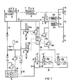
- a bypass line 4 bypasses the quick-closing cap 1 and connects the line section 3a to the section 3b.
- the bypass line 4 is provided with two shut-off valves 5a, 5b for redundancy reasons, which can be closed simultaneously with the quick-closing flap 1.
- the bypass line 4 and its shut-off elements 5a, 5b are dimensioned for a steam flow which is at least somewhat larger than the leakage flow of the closed control valve 2.
- Quick-closing flap 1 and the shut-off valves 5a, 5b are spring-loaded in a safety-related manner so that they close automatically when there are malfunctions in the electronics or hydraulics.
- the quick-closing flap 1 has a rotary shaft 11 which is guided outwards through the steam line on at least one side and is provided with a pinion 12 at its end. With the pinion 12 are two pairs of racks 13, 14 in engagement.
- a pair of racks 13 can be actuated by hydraulic opening pistons 6, which slide in hydraulic cylinders 8, and serves to open the quick-closing flap 11.
- Another pair of racks 14, which is completely independent of the first one is connected to closing springs 7 and acts in the closing direction the quick-closing flap 1.
- the associated hydraulic system consists of a container 18 with hydraulic fluid, a pump 19 which, if necessary, delivers hydraulic fluid to a reservoir 20 or a hydraulic fluid feed line 21 into the hydraulic cylinders 8 via non-described check valves.
- the quick-closing flap 1 can be opened and remains open until the hydraulic fluid in the hydraulic cylinders 8 opens a drainage path becomes what leads to the triggering of the quick close.
- Such a drainage path is provided by the drain lines 22, 25, 28 when the safety-related drain valves 24a, 24b are opened by their controller 23a, 23b.
- valves 34a, 34b Simultaneously with the valves 24a, 24b, the valves 34a, 34b also open, which close the shut-off valves 5a, 5b in the bypass line 4.
- a quick close should shut off the steam line 3a, 3b, 3c within about 100 milliseconds.
- the high speed of the quick-closing flap required for this makes it necessary that the hydraulic fluid in the hydraulic cylinders 8 can initially flow out very quickly.
- the hydraulic fluid flow ejected from the hydraulic cylinders 8 is reduced towards the end of the closing process.
- a minimum current can always flow through a throttle point 30 to the discharge line 28, but initially existing partial flows are changed by an intercepting throttle 27 and a throttle point 29 as well as by pressure compensators 26a, 26b and the associated adjustable throttle points depending on the position of the rotary shaft 11.
- cam disks (not shown) can be fastened on the rotary shaft 11, which change the spring preloads of the intercepting throttle 27 or pressure compensators 26a, 26b depending on the angle of rotation by means of mechanical tappets.
- an adjustable intercepting throttle 27 which would be greatly reduced in cross section, for example, from an angle of rotation of 79 °, ie 11 ° before the closing end position, would be sufficient to dampen the flap plate.
- the outflow throttle 27 is preceded by a hydraulic pressure compensator 26a, which the Differential pressure above the discharge throttle 27 maintains a constant or predeterminable value depending on the angle of rotation.
- the working areas in hydraulic pressure compensators are limited are preferably two such devices 26a, 26b connected in parallel.
- the two pressure compensators can be adjusted from a rotation angle of 80 ° or 85 ° with a different spring preload by means of a cam disc in order to achieve a desired damping characteristic regardless of the form.
- shut-off valves 5a, 5b with their spring-loaded drives 32a, 32b generally do not require a separate damping device, so that they close immediately when the valves 34a, 34b are opened. If the quick-closing flap 1 is to be opened again, the switch 35 is closed and the pump 19 begins to deliver hydraulic fluid. As a result, the valves 24a, 24b, 34a, 34b are closed and, via the valve control 31, the shut-off valve drives 32a, 32b are initially acted upon with pressurized fluid, so that the valves 5a, 5b open.
- a pinion 12 is arranged, with which the rack pairs 13, 14 are in engagement.
- the racks 13, 14 are each guided in guide bushes 15, which are open laterally only in the area of the pinion 12.
- the guide bushes 15 are incorporated in a housing block 16.
- Above the housing block 16 is a control room 17, in which the hydraulic controls and the other elements of the hydraulic circuit are arranged.
- the rotary shaft 11 protrudes into this control chamber 17 and can optionally carry cam disks there, which are in engagement with individual elements of the hydraulic Circuit if they are to be changed depending on the angle of rotation.
- the present invention is suitable as a drive for quick closing flaps in steam lines of steam turbine systems, in particular also for high pressures and large nominal widths of the steam lines.
Landscapes
- Engineering & Computer Science (AREA)
- Mechanical Engineering (AREA)
- General Engineering & Computer Science (AREA)
- Physics & Mathematics (AREA)
- Fluid Mechanics (AREA)
- Control Of Turbines (AREA)
- Mechanically-Actuated Valves (AREA)
- Fluid-Driven Valves (AREA)
- Quick-Acting Or Multi-Walled Pipe Joints (AREA)
- Pens And Brushes (AREA)
Priority Applications (1)
| Application Number | Priority Date | Filing Date | Title |
|---|---|---|---|
| AT89113594T ATE68856T1 (de) | 1988-08-04 | 1989-07-24 | Einrichtung zur betaetigung einer schnellschlussklappe. |
Applications Claiming Priority (2)
| Application Number | Priority Date | Filing Date | Title |
|---|---|---|---|
| DE3826592A DE3826592A1 (de) | 1988-08-04 | 1988-08-04 | Einrichtung zur betaetigung einer schnellschlussklappe |
| DE3826592 | 1988-08-04 |
Publications (3)
| Publication Number | Publication Date |
|---|---|
| EP0353586A2 true EP0353586A2 (fr) | 1990-02-07 |
| EP0353586A3 EP0353586A3 (en) | 1990-05-30 |
| EP0353586B1 EP0353586B1 (fr) | 1991-10-23 |
Family
ID=6360278
Family Applications (1)
| Application Number | Title | Priority Date | Filing Date |
|---|---|---|---|
| EP89113594A Expired - Lifetime EP0353586B1 (fr) | 1988-08-04 | 1989-07-24 | Commande pour un clapet de fermeture rapide |
Country Status (3)
| Country | Link |
|---|---|
| EP (1) | EP0353586B1 (fr) |
| AT (1) | ATE68856T1 (fr) |
| DE (2) | DE3826592A1 (fr) |
Cited By (1)
| Publication number | Priority date | Publication date | Assignee | Title |
|---|---|---|---|---|
| CN104197080A (zh) * | 2014-06-09 | 2014-12-10 | 常州机电职业技术学院 | 阀门快开快关液压控制系统 |
Families Citing this family (1)
| Publication number | Priority date | Publication date | Assignee | Title |
|---|---|---|---|---|
| DE10111187C1 (de) * | 2001-03-08 | 2002-07-25 | Siemens Ag | Dampfleitungsverschlußventil und Dampfturbinenanlage mit Dampfleitungsverschlußventil |
Family Cites Families (5)
| Publication number | Priority date | Publication date | Assignee | Title |
|---|---|---|---|---|
| DE362149C (de) * | 1920-10-12 | 1922-10-24 | Georg Einhorn | Bogen-An- und Auslegevorrichtung fuer Tiegeldruckpressen |
| US3591127A (en) * | 1968-09-30 | 1971-07-06 | Ametak Inc | Butterfly valve structure with combined translation and rotary movements |
| DE2655493C3 (de) * | 1976-12-08 | 1979-05-23 | Ing.-Buero Pfannenschmidt Gmbh, 2000 Hamburg | Druckmittelbetätigter Drehantrieb für ein Ventil |
| DE3606102A1 (de) * | 1986-02-26 | 1987-08-27 | Amg Antrieb Mechanik Gmbh | Schwenkantrieb |
| DE3621489A1 (de) * | 1986-06-27 | 1988-01-07 | Waldorf Veronika | Vorrichtung zum umsetzen einer linearbewegung in eine drehbewegung |
-
1988
- 1988-08-04 DE DE3826592A patent/DE3826592A1/de not_active Withdrawn
-
1989
- 1989-07-24 AT AT89113594T patent/ATE68856T1/de not_active IP Right Cessation
- 1989-07-24 DE DE8989113594T patent/DE58900399D1/de not_active Expired - Lifetime
- 1989-07-24 EP EP89113594A patent/EP0353586B1/fr not_active Expired - Lifetime
Cited By (1)
| Publication number | Priority date | Publication date | Assignee | Title |
|---|---|---|---|---|
| CN104197080A (zh) * | 2014-06-09 | 2014-12-10 | 常州机电职业技术学院 | 阀门快开快关液压控制系统 |
Also Published As
| Publication number | Publication date |
|---|---|
| DE58900399D1 (de) | 1991-11-28 |
| EP0353586A3 (en) | 1990-05-30 |
| ATE68856T1 (de) | 1991-11-15 |
| DE3826592A1 (de) | 1990-02-08 |
| EP0353586B1 (fr) | 1991-10-23 |
Similar Documents
| Publication | Publication Date | Title |
|---|---|---|
| EP0126291A2 (fr) | Soupape commandée par un fluide sous pression | |
| DE1916266A1 (de) | Elektrohydraulisches Stellgeraet | |
| EP0141301B1 (fr) | Circuit hydraulique pour un moteur entraînant une charge | |
| EP0433791B1 (fr) | Actuateur pour une valve d'alimentation | |
| DE2832898C2 (de) | Irreversibler, hydraulischer Stellantrieb | |
| EP0353586B1 (fr) | Commande pour un clapet de fermeture rapide | |
| EP1451474A1 (fr) | Dispositif d'entrainement | |
| EP0505349B2 (fr) | Vérin hydraulique | |
| EP0163861B1 (fr) | Dispositif de manoeuvre de porte | |
| DE3812116C2 (de) | Elektrohydraulisches Wegeventil | |
| DE3234615A1 (de) | Tuerbetaetigungsvorrichtung | |
| DE4244304A1 (de) | Betätigungsvorrichtung für einen hydraulischen Stellantrieb mit druckproportionalem Stellsignal | |
| DE2322998C3 (de) | Hydraulische Stelleinrichtung, insbesondere für eine Lenkung | |
| EP0111617A1 (fr) | Dispositif opérateur actionné par fluide sous pression avec organe de verrouillage | |
| DE3041788C2 (de) | Antriebsvorrichtung für den Schieberverschluß eines metallurgischen Gefäßes | |
| DE2046461C3 (de) | Steuereinrichtung für einen zwei Pumpen und mehrere Verbraucher besitzenden hydraulischen Antrieb, vorzugsweise für Universalbagger | |
| DE2450330C3 (de) | Doppelhydraulischer Stellantrieb | |
| DE69102342T2 (de) | Steuerkreis für einen hydraulischen, doppelt wirkenden Zylinder und ein Schieberventil für solch einen Kreislauf. | |
| DE102025102960B3 (de) | Vorrichtung zur Steuerung eines Ring-Gates einer Wasserkraftanlage und Wasserkraftanlage mit einer solchen Vorrichtung | |
| DE19505333C2 (de) | Hydraulikantrieb | |
| DE2835063A1 (de) | Hydraulischer antrieb | |
| DE112004000191B4 (de) | Antrieb für ein Turbinenventil | |
| DE474210C (de) | Einrichtung zur Sicherung mehrstufiger Dampfturbinen fuer hochgespannten Dampf und mi Zwischenueberhitzung gegen UEberschreitung der zulaessigen Umdrehungszahl | |
| DE2108545C (de) | Doppelhydraulischer Stellantrieb | |
| EP0487755B1 (fr) | Système électrohydraulique d'actionnement de barrière |
Legal Events
| Date | Code | Title | Description |
|---|---|---|---|
| PUAI | Public reference made under article 153(3) epc to a published international application that has entered the european phase |
Free format text: ORIGINAL CODE: 0009012 |
|
| AK | Designated contracting states |
Kind code of ref document: A2 Designated state(s): AT CH DE FR GB LI SE |
|
| RIN1 | Information on inventor provided before grant (corrected) |
Inventor name: KINDERMANN, WOLFGANG |
|
| PUAL | Search report despatched |
Free format text: ORIGINAL CODE: 0009013 |
|
| AK | Designated contracting states |
Kind code of ref document: A3 Designated state(s): AT CH DE FR GB LI SE |
|
| 17P | Request for examination filed |
Effective date: 19900625 |
|
| 17Q | First examination report despatched |
Effective date: 19910125 |
|
| GRAA | (expected) grant |
Free format text: ORIGINAL CODE: 0009210 |
|
| AK | Designated contracting states |
Kind code of ref document: B1 Designated state(s): AT CH DE FR GB LI SE |
|
| PG25 | Lapsed in a contracting state [announced via postgrant information from national office to epo] |
Ref country code: SE Effective date: 19911023 Ref country code: GB Effective date: 19911023 Ref country code: FR Effective date: 19911023 |
|
| REF | Corresponds to: |
Ref document number: 68856 Country of ref document: AT Date of ref document: 19911115 Kind code of ref document: T |
|
| REF | Corresponds to: |
Ref document number: 58900399 Country of ref document: DE Date of ref document: 19911128 |
|
| EN | Fr: translation not filed | ||
| GBV | Gb: ep patent (uk) treated as always having been void in accordance with gb section 77(7)/1977 [no translation filed] | ||
| PG25 | Lapsed in a contracting state [announced via postgrant information from national office to epo] |
Ref country code: AT Effective date: 19920724 |
|
| PG25 | Lapsed in a contracting state [announced via postgrant information from national office to epo] |
Ref country code: LI Effective date: 19920731 Ref country code: CH Effective date: 19920731 |
|
| PLBE | No opposition filed within time limit |
Free format text: ORIGINAL CODE: 0009261 |
|
| STAA | Information on the status of an ep patent application or granted ep patent |
Free format text: STATUS: NO OPPOSITION FILED WITHIN TIME LIMIT |
|
| 26N | No opposition filed | ||
| REG | Reference to a national code |
Ref country code: CH Ref legal event code: PL |
|
| PG25 | Lapsed in a contracting state [announced via postgrant information from national office to epo] |
Ref country code: DE Effective date: 19930401 |