EP0353644A2 - Fenêtres de corrélation configurables pour la mesure directe de distorsion différentielle de champs - Google Patents
Fenêtres de corrélation configurables pour la mesure directe de distorsion différentielle de champs Download PDFInfo
- Publication number
- EP0353644A2 EP0353644A2 EP89113939A EP89113939A EP0353644A2 EP 0353644 A2 EP0353644 A2 EP 0353644A2 EP 89113939 A EP89113939 A EP 89113939A EP 89113939 A EP89113939 A EP 89113939A EP 0353644 A2 EP0353644 A2 EP 0353644A2
- Authority
- EP
- European Patent Office
- Prior art keywords
- correlation
- window
- image
- images
- storage means
- Prior art date
- Legal status (The legal status is an assumption and is not a legal conclusion. Google has not performed a legal analysis and makes no representation as to the accuracy of the status listed.)
- Withdrawn
Links
Images


Classifications
-
- G—PHYSICS
- G06—COMPUTING OR CALCULATING; COUNTING
- G06F—ELECTRIC DIGITAL DATA PROCESSING
- G06F17/00—Digital computing or data processing equipment or methods, specially adapted for specific functions
- G06F17/10—Complex mathematical operations
- G06F17/15—Correlation function computation including computation of convolution operations
- G06F17/153—Multidimensional correlation or convolution
-
- G—PHYSICS
- G06—COMPUTING OR CALCULATING; COUNTING
- G06T—IMAGE DATA PROCESSING OR GENERATION, IN GENERAL
- G06T7/00—Image analysis
- G06T7/20—Analysis of motion
-
- G—PHYSICS
- G06—COMPUTING OR CALCULATING; COUNTING
- G06V—IMAGE OR VIDEO RECOGNITION OR UNDERSTANDING
- G06V10/00—Arrangements for image or video recognition or understanding
- G06V10/70—Arrangements for image or video recognition or understanding using pattern recognition or machine learning
- G06V10/74—Image or video pattern matching; Proximity measures in feature spaces
- G06V10/75—Organisation of the matching processes, e.g. simultaneous or sequential comparisons of image or video features; Coarse-fine approaches, e.g. multi-scale approaches; using context analysis; Selection of dictionaries
- G06V10/751—Comparing pixel values or logical combinations thereof, or feature values having positional relevance, e.g. template matching
- G06V10/7515—Shifting the patterns to accommodate for positional errors
Definitions
- This invention relates to an image processing system for measuring and correlating field distortions such as rotation, expansion or shear, typically after translation disparities have been removed between a pair of image regions.
- the system allows relative field distortions to be applied between a pair of image regions as correlations between the regions are performed.
- a common problem in image processing is the comparison of two images such as a stored template and an acquired image.
- a frequent goal of such comparisons is to determine whether the two images "match,” or if they do not, to determine the angle of rotation, amount of magnification, extent of shear, or, more generally, the field distortion between the two images.
- Such comparisons are termed "area" correlations herein. Area correlations can be measured against parameters such as rotation or magnification to determine the values of those parameters that give the best agreement between images, thereby providing quantitive information about the two images.
- the principal difficulty with making such measurements is the requirement that one of the two images must be distorted, for example, by rotating, expanding, or shearing it by various amounts relative to the other image.
- Area correlation of images or regions of images can be used directly to measure field distortions such as rotation, expansion, or shear once translation disparities have been removed between the pair of image regions.
- the present correlator design, and the method of employing it, allow relative field distortions to be applied between a pair of image regions as they are correlated.
- This method has applications to binocular stereo where it can be used to directly measure elevation gradients and surface curvature, to motion analysis where it can be used to directly measure flow field parameters such as divergence and curl, and to template matching where rotation and magnification can be measured without requiring multiple templates for the same object.
- the system of this invention decouples the field distortion mechanism of the correlation process from the images that are correlated by allowing correlation windows to be specified on a point-by-point basis, rather than as rectangular regions.
- a 1000-point correlation would entail the storage of 1000-point pairs in a correlation window table having entries of the form: [(xa,ya), (xb,yb)].
- the (xa,ya) point in the first window is compared with the (xb,yb) position in the second window, which might be on the same image or a different image depending on te application. Different offsets can be added to the positions in each window to position each of them over the desired part of the images being compared.
- a Laplacian of Gaussian filter to extract information from each image.
- special purpose hardware has been developed for rapidly filtering the acquired pixel data. For commercial applications, it is essential that such filtering be performed in real time with relatively inexpensive apparatus.
- the system includes apparatus for collecting the desired pixel data, computing both the Laplacian and Gaussian of that data, and then correlating the sign of the result with other stored or acquired pixel data, all in real time.
- the system of this invention may be employed in many different applications, for example, in stereo matching of pairs of images to determine surface elevation gradients, in measurement of flow field parameters by comparison of successive images in a time sequence of images, in inspection problems where a stored template is to be compared with an image distorted by magnification, shear or rotation, as well as other applications.
- Different types of images may be employed by the system, for example, range images in which an object is scanned with a laser beam offset from a camera or conventional intensity images.
- intensity images for detecting motion between two image frames are used for illustration. Below the method by which the field distortions are measured is first described, then the technique by which the images to be compared are individually processed, and then the apparatus for comparing the images.
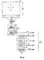
- FIG. 1 is a block diagram illustrating the overall correlation system.
- two images 10a and 10b are supplied as input information to the process.
- the apparatus If the apparatus is to be applied to stereo matching to measure surface elevation gradients directly, then the images will be binocular images 11a and 11b taken from different viewpoints. Elevation gradients in the vertical direction--perpendicular to the axis of the stereo-camera pair--cause a horizontal shear between left and right images. An elevation gradient parallel to the axis of the camera pair creates a horizontal compression/expansion effect between left and right images.
- a correlation based stereo matching system measuring distortion can provide information about elevation gradients directly once translation disparities have been measured and nulled between the images.
- the technique can also be used to directly compensate for the disparity effects of nonplanar surfaces, thereby providing a method of measuring surface topography in single measurements.
- the two images are each filtered to attenuate higher spatial frequencies while preserving some of the lower spatial frequencies.
- These steps are represented by filter blocks 33a and 33b. The filtering is described in more detail below in conjunction with Figures 2-4.
- the resulting images are each stored, with the first image being stored in image memory A 81a and the other image stored in image memory B 81b.
- Typical storage units comprise static random access memories, which can be configured as dual-ported memories. Either storage 81a or 81b can be established once and then reused so long as the particular image is not changed.
- the locations in the image memories at which the images are stored is controlled by address generator counters 82a and 82b.
- the address generator counters 82 typically include a first counter for identifying a unique horizontal line, and a second counter for identifying a pixel position on that line.
- the addresses from which data in the memory 81 are read are controlled ultimately by counter 83 and x,y registers 84.
- X,y registers 84 provide information regarding the center point of a correlation window on the image. By varying the position of the window's center point, one image may be shifted with respect to the other, and the regions from each image can be selected.
- Counter 83 counts the number of points in a window stored in one memory to be compared with the other image data in the other memory, while correlation tables 85 provide information regarding the offset relative to the base position 84 of each image point to be compared within the window.
- the corresponding offsets in tables 85a and 85b can differ according to the type of distortion (such as rotation) against which a correlation measurement is to be made.
- Each table 85 supplies x and y offset values which are added to a base position to set the overall position of the window on the image.
- the values in these registers are also adjusted to cancel any translation disparities that exist between the A and B images at the window position.
- the resulting x and y positions together form a memory address which is sent to the image memory buffers 81.
- the image buffers supply pixel values which are correlated and the result is added to an accumulator 93.
- the offset tables 85 typically contain between 1000 and 4000 points for each correlation window.
- the image memories 81a and 81b store just the sign bit of the Laplacian of Gaussian convolution of the input images 10a and 10b.
- the correlator is an XOR gate while the accumulator 93 is a counter.
- a window number register 95 allows each of the correlation window table memories to store data for more than one window by enabling selection of a particular window.
- the window tables described above allow flexibility in tailoring the shape of the correlation windows--for example, as a square, a circle, or a Gaussian scatter plot. This flexibility is discussed further below.
- the integer coordinate pairs could define a window such that x + y ⁇ 202.
- the points (p n ) are loaded into table 85a of Figure 1 and the points (q n ) are loaded into table 85b, rounding the coordinate values to integral pixel locations as necessary.
- the image of the pattern or object to be compared with itself or with another image may be acquired using any desired technique, for example, with a vidicon, CCD camera, scanning electron microscope, range camera, or other apparatus.
- the images to be compared will be generated by the user of the system.
- alignment targets for object alignment may be built from isolated fine scale marks. These fine marks can be spread out in a pattern in a two-dimensional array to form a target as shown in Figure 2a.
- the fine scale features may consist of small "dots" distributed in an array.
- the array consists of a matrix of 50x50 potential dot locations. The actual locations for dots in the array of 50x50 potential dots are randomly selected.
- Figure 2a is an image of Figure 2a but which includes field distortion.
- Figure 2b is the same pattern with a 2° rotation about its center and a 4% expansion.
- Figure 2c is the superposition of Figures 2a and 2b, and illustrates the spiral flow pattern of the combined fields.
- the image(s) is acquired, for example, Figure 2a, it is digitized and a filtering operation is performed to enhance the low frequency structure in the pattern while attenuating the high frequency information.
- a Laplacian of Gaussian ( ⁇ 2G) convolution operator is used.
- the Gaussian is a two-dimensional Gaussian which functions to low pass filter the image in a way that attenuates high spatial frequencies while preserving the geometric structure at lower spatial frequencies.
- the size of the Gaussian controls the scale at which structure remains in the filtered image.
- the Laplacian term detects locations in the low pass filtered image where local maxima in the rate of brightness change occur.
- Figure 3a corresponds to Figure 2a
- Figure 3b corresponds to Figure 2b.
- the black regions of Figures 3a and 3b are locations where the sign of the filtered image is negative.
- Figure 3c shows the difference between Figure 3a and Figure 3b.
- the black areas are locations where the filtered result of the images in Figure 2a and 2b differ in sign.
- the center of Figure 3c is the most similar--little black--because the expansion and rotation centers are at the middle and have the least effect there. Further out from the middle of Figure 3c the relative motion between images increases linearly and more black is seen.
- the number of white pixels minus the number of black ones divided by the total number of pixels in Figure 3c is equivalent to the cross correlation measured between Figures 2a and 2b using the same correlation window on each image--that is, correlating with a magnification of 1.0 and rotation of 0 degrees.
- the filtering operation may be performed using a suitably programmed conventional general purpose digital computer. While this is feasible, the use of conventional digital computers is undesirably slow. Because commercial applications of the system compel alignment much more quickly, a processor with a special architecture may be employed to perform the necessary calculations.
- this technique exhibits in its sign pattern structures correlated with the clustering structure of the original dot pattern and not with individual dots. Because the sign pattern is thus tied to the overall position of the dot pattern on the image surface, and not with any particular location for any finer feature, it is insensitive to small distortions such as fringe effects, blurring, interference, dirt, noise, etc., which are present in the imaging. Thus, coarse scale structure of the patterns is captured, yet in view of the relatively insensitivity to high frequency noise, it is ideally suited to electronically acquired images, which typically exhibit significant noise. These filtered images are stored in memories 81a and 81b.
- the correlation of C(x,y) when the image I(x,y) is taken to be Gaussian white noise has the form where k is a constant and W is the diameter of the negative central region of the ⁇ 2G convolution function.
- the correlation R s ( ⁇ ) of the sign of Eq. (3), S(x,y) sgn[C(x,y)], obeys an arcsin law when C is a Gaussian random process.
- Figure 4 shows the correlation function of the sign of a Laplacian of Gaussian convolution.
- Figure 4 when a pattern such as depicted in Figure 3a is compared with itself, a single strongly correlated location, corresponding to the peak of the cone in Figure 4, results. Misalignment, in any direction by any significant amount, results in a much lower correlation.
- the width of the base of the cone is controlled largely by the size of the filter employed, with larger filters providing broader cones.
- the sharpness of the peak is due to the binary nature of the filtered image.
- the use of the sign, rather than the raw convolution values, also causes the correlation peak to be normalized with a height of one in the absence of noise.
- a first search can be made to find the translation disparity between the two images assuming no field distortion. Once the proper alignment between the two images is found, adjustments can be made to the contents of the base position registers 84 to null out translation disparities between the two images stored in 81a and 81b.
- the correlation window tables can be changed to measure each independent field distortion of interest separately, assuming all other field distortions are zero. For example, to measure the magnitude of a small rotation between the two images, three correlations can be carried out, one imposing a negative rotation, one a zero rotation, and the third a positive rotation between the images. Because the correlation peaks are fairly broad and the extent of correlation at one or more of these points will be greater than at other points, the values at these three points on the rotation axis can be used to estimate the position of the actual peak provided it lies within the span of the three measurements. Subsequent measurements may then be made to more precisely pinpoint the location of that peak.
- magnification can be measured individually.
- five correlation measurements can be measured simultaneously, making possible the measurement of pairs of field distortions, such as magnification and rotation, together.
- Figure 5a is a plot which shows the extent of correlation between Figures 3a and 3b using configurable window rotations of -4°, 0° and 4°. Each of these points is represented by an "X" in Figure 5a. A quadratic function is used to fit to the data points to create the curve shown. The dashed vertical line in Figure 5a indicates the position of the peak of the curve, while the heavier line next to it represents the position of the actual amount of rotation between the two patterns (2°).
- Figure 5b shows similar results for correlations against magnifications of 0.9, 1.0 and 1.1 while holding the rotation constant at 0°.
- Figure 5c presents three cross-correlations taken between Figures 3a and 3b using rotations of 1°, 2° and 3° with a magnification of 1.0.
- Figure 5d presents similar results for magnifications of 1.01, 1.03 and 1.05.
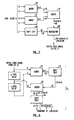
- the image In the case of either retrieval of a stored pattern or acquisition of an image through optical means, a digital representation of the image is required. Thus, for analog images the image must first be digitized using, for example, a commercially available A/D converter operating at video rates. For explanation, assume that in the preferred embodiment, the pattern to be filtered is displayed in an area of approximately 500x500 pixels.
- the 500-pixel square image 40 is shown at the top of Figure 6. If the Laplacian function is to be applied to pixel C, then the 8-bit binary value for each of pixels A-E must be retrieved and appropriately weighted.
- the apparatus of Figure 6 illustrates one technique for retrieving the desired pixels. As the desired pattern is acquired as a noninterlaced video raster scan, either from memory 44 or from camera 42 and A-D converter 43, at some given instant pixel A will be supplied on line 45. At that time, line 46 will carry B, the value received 499 pixels earlier. Similarly, lines 47, 48, and 49 will hold pixels C, D, and E, respectively, which were received 500, 501, and 1000 pixels earlier than A.
- this configuration produces five simultaneous samples making a cross pattern from the image, as shown at the top of Figure 6.
- the entire cross pattern of samples will move one pixel to the right on the image following the raster scan.
- the delay elements 50 shown in Figure 6 may comprise any known delay elements, for example, a shift register or a random access memory. Switches 51 and 52 control whether the pixels latched are from a retrieved pattern 44 or an acquired image 40.
- Figure 7 illustrates apparatus for obtaining the Laplacian of the acquired pixel values.
- a satisfactory approximation to the Laplacian function at a given pixel location is to apply a weight of 4 to that particular pixel and a weight of -1 to the pixels above, below, to the left, and to the right of the specified pixel.
- the pixel values for pixels A and B are supplied to adder 60, while those for pixels D and E are supplied to adder 61.
- adder 6D supplies an output signal A + B on line 62
- adder 61 supplies an output signal D + E on line 63.
- Another adder 64 connected to receive the signals on line 62 and 63 then supplies an output signal on line 65 indicative of the sum of all of pixels A, B, D, and E.
- the pixel value for pixel C is supplied to a shifter 66. By shifting the pixel value two places left, the value is effectively multiplied by four, and the results supplied on line 67 to subtractor 68.
- Subtractor 68 combines the sum supplied on line 65 with the quadruply-weighted value on line 67 to achieve a new value which approximates the Laplacian at pixel C of the input image.
- the output 68 carries a video raster signal of the Laplacian of the input image. This signal is fed to the next stage of processing, the Gaussian convolver.
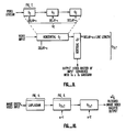
- Figure 8 illustrates the operation of the three-point mechanism, G3.
- a digital raster input is applied to the input of two serially-connected delay elements. These delay elements will both introduce a delay of n pixels between their input and output terminals, where n equals one or two pixels for horizontal convolutions and u equals the image line length or twice the image line length for vertical convolutions. From these delay elements we obtain three simultaneous values A, B, and C separated by n pixels from each other in the image.
- a and C are applied to adder 70 and the sum supplied on line 71 to a shifter 72. Shifter 72 shifts the sum of A + C one place to the right, in effect dividing it by two.
- the output signal on line 73 is supplied to adder 74 in conjunction with the binary value for pixel B.
- Adder 74 thereby provides on line 75 a value equal to the sum of the value of pixel B plus one-half the sum of values of pixels A and C. To maintain correct amplitude, this result is shifted right one place by shifter 76, and the result supplied on line 77.
- the result on line 77 is the input signal smoothed by a three-point binomial distribution. To obtain a finer approximation to the Gaussian, the procedure of Figure 8 may be repeated more than once as shown in Figure 9.
- Figure 9 illustrates how a pipeline of three Gaussian convolution three-point elements G3 of Figure 6 is configured.
- This device convolves the input video stream with a 7-point binomial approximation to a one-dimensional Gaussian G7. If the delay elements are set to produce a delay of one pixel, this will provide a horizontal Gaussian convolution. If the delay elements are set to the line length of the image, this will provide a vertical convolution.
- One of the G3 operators of each G7 operator does not include the normalization operation for the reasons discussed above.
- FIG. 8 illustrates my technique using a pipeline of two G7 elements to produce a G 7x7 element.
- a larger Gaussian filter than the 7x7 operator described is required. Similar techniques as described above could be used to build arbitrarily large filters; however, there is a more efficient approach.
- the input signal has been low pass filtered sufficiently that a subsequent operator that samples only every other pixel will not suffer from aliasing problems.
- a 14x14 Gaussian convolution can be approximated by the G 7x7 operator with its points spread out by increasing its horizontal delays from one to two pixels and its vertical delays from one line length to two line lengths.
- Figure 10 shows two G 7x7 elements configured in this way to produce effectively a 21x21 Gaussian convolution operator in a video pipeline with the Laplacian operator at the start.
- the result is a ⁇ 2G filtered image.
- This image may be supplied to suitable storage means, for example, a random access memory such as described in conjunction with block 81 of Figure 1. Because only the sign of the result is saved, the filtered image will be a binary one, having the appearance, for example, of Figure 3.
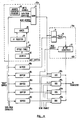
- FIG 11 is a more detailed block diagram of one embodiment of the correlator previously shown in block form in Figure 1.
- the components shown in Figure 11 are driven by a 10-megaHertz pixel clock.
- the filtered image input data (from Figure 10) is supplied in parallel to six buffer networks 80a-80f shown in Figure 11.
- the contents of one of the buffers 80a is shown in greater detail; similar components make up each of the remaining buffers 80b-80f.
- Buffer 80 includes a 64k-by-1 bit memory 81 for storing approximately one-quarter of the image.
- memory 81 is a static random access memory and stores 256x256 pixels of data.
- the choice of the size of memory 81 is arbitrary, and larger or smaller memories may be employed depending upon the particular application for the correlator of Figure 11. Storage of the convolver output data in memory 81 allows scanning of the contents of the memory for purposes of image correlation.
- the data from the convolver are supplied both to the left buffer 80a and the right buffers 80b-80f.
- the left buffer, 80a will be filled with convolver data from one image.
- the right buffers would then be filled with convolver data from the other image.
- the use of six buffers allows five values to be generated by the exclusive OR networks 90a-90e during each cycle.
- the left buffer allows one image to be used for comparison, while the five right buffers allow five locations in the other image to be examined in parallel. These five ports onto the image allow five points on the same correlation surface to be computed in parallel.
- Each of the exclusive OR networks 90a-90e contains a latch 91, an exclusive OR gate 92, and one or more counters depending upon the number of bits of counting desired.
- Latch 91 holds the output value from the left buffer and one of the right buffers (depending upon which exclusive OR network) and supplies the resulting data to the exclusive OR gate 92.
- OR gate 92 drives desired counters to provide as many bits of accuracy as desired.
- a 12-bit counter 93 is provided by three smaller 4-bit counters. Read enable lines coupled to the counters 93 enable supplying the output from a desired counter to a transceiver (not shown).
Landscapes
- Engineering & Computer Science (AREA)
- Physics & Mathematics (AREA)
- Theoretical Computer Science (AREA)
- General Physics & Mathematics (AREA)
- Computer Vision & Pattern Recognition (AREA)
- Software Systems (AREA)
- Computing Systems (AREA)
- Pure & Applied Mathematics (AREA)
- Computational Mathematics (AREA)
- Data Mining & Analysis (AREA)
- Mathematical Physics (AREA)
- Databases & Information Systems (AREA)
- Mathematical Analysis (AREA)
- Mathematical Optimization (AREA)
- Multimedia (AREA)
- General Engineering & Computer Science (AREA)
- Algebra (AREA)
- Health & Medical Sciences (AREA)
- Artificial Intelligence (AREA)
- Evolutionary Computation (AREA)
- General Health & Medical Sciences (AREA)
- Medical Informatics (AREA)
- Image Analysis (AREA)
- Image Processing (AREA)
Applications Claiming Priority (2)
| Application Number | Priority Date | Filing Date | Title |
|---|---|---|---|
| US22861288A | 1988-08-04 | 1988-08-04 | |
| US228612 | 1988-08-04 |
Publications (2)
| Publication Number | Publication Date |
|---|---|
| EP0353644A2 true EP0353644A2 (fr) | 1990-02-07 |
| EP0353644A3 EP0353644A3 (fr) | 1991-05-15 |
Family
ID=22857904
Family Applications (1)
| Application Number | Title | Priority Date | Filing Date |
|---|---|---|---|
| EP19890113939 Withdrawn EP0353644A3 (fr) | 1988-08-04 | 1989-07-28 | Fenêtres de corrélation configurables pour la mesure directe de distorsion différentielle de champs |
Country Status (2)
| Country | Link |
|---|---|
| EP (1) | EP0353644A3 (fr) |
| JP (1) | JPH02141881A (fr) |
Cited By (7)
| Publication number | Priority date | Publication date | Assignee | Title |
|---|---|---|---|---|
| DE4015390A1 (de) * | 1990-05-14 | 1991-11-21 | Nokia Unterhaltungselektronik | Verfahren zum berechnen des inhalts eines zwischenbildes zu jeweils zwei aufeinanderfolgenden monitorbildern |
| WO1992006444A1 (fr) * | 1990-09-28 | 1992-04-16 | Eastman Kodak Company | Mecanisme servant a determiner la parallaxe entre des images numeriques |
| GB2285359A (en) * | 1993-12-31 | 1995-07-05 | Philips Electronics Uk Ltd | Disparity coding images for bandwidth reduction |
| WO1996018158A1 (fr) * | 1994-12-09 | 1996-06-13 | United Parcel Service Of America, Inc. | Procede et appareil pour la convolution simultanee de multiples images binaires numeriques a l'aide d'un seul convolutionneur dote d'un masque binaire pour determiner les densites de pixels |
| EP1286299A3 (fr) * | 2001-07-30 | 2004-07-07 | Agilent Technologies, Inc. | Système d'interpolation simplifié pour un système de navigation optique |
| RU2251738C2 (ru) * | 2003-01-28 | 2005-05-10 | "Аби Софтвер Лтд." | Способ приведения в соответствие заполненной машиночитаемой формы и ее шаблона при наличии искажений (варианты) |
| CN110308302A (zh) * | 2019-07-01 | 2019-10-08 | 北京大学 | 一种近壁面流速测量方法及装置 |
Family Cites Families (2)
| Publication number | Priority date | Publication date | Assignee | Title |
|---|---|---|---|---|
| EP0005918B1 (fr) * | 1979-05-09 | 1983-05-04 | Hughes Aircraft Company | Système de poursuite d'image |
| US5119444A (en) * | 1986-07-22 | 1992-06-02 | Schlumberger Technologies, Inc. | System for expedited computation of laplacian and gaussian filters and correlation of their outputs for image processing |
-
1989
- 1989-07-28 EP EP19890113939 patent/EP0353644A3/fr not_active Withdrawn
- 1989-08-04 JP JP1201460A patent/JPH02141881A/ja active Pending
Cited By (7)
| Publication number | Priority date | Publication date | Assignee | Title |
|---|---|---|---|---|
| DE4015390A1 (de) * | 1990-05-14 | 1991-11-21 | Nokia Unterhaltungselektronik | Verfahren zum berechnen des inhalts eines zwischenbildes zu jeweils zwei aufeinanderfolgenden monitorbildern |
| WO1992006444A1 (fr) * | 1990-09-28 | 1992-04-16 | Eastman Kodak Company | Mecanisme servant a determiner la parallaxe entre des images numeriques |
| GB2285359A (en) * | 1993-12-31 | 1995-07-05 | Philips Electronics Uk Ltd | Disparity coding images for bandwidth reduction |
| WO1996018158A1 (fr) * | 1994-12-09 | 1996-06-13 | United Parcel Service Of America, Inc. | Procede et appareil pour la convolution simultanee de multiples images binaires numeriques a l'aide d'un seul convolutionneur dote d'un masque binaire pour determiner les densites de pixels |
| EP1286299A3 (fr) * | 2001-07-30 | 2004-07-07 | Agilent Technologies, Inc. | Système d'interpolation simplifié pour un système de navigation optique |
| RU2251738C2 (ru) * | 2003-01-28 | 2005-05-10 | "Аби Софтвер Лтд." | Способ приведения в соответствие заполненной машиночитаемой формы и ее шаблона при наличии искажений (варианты) |
| CN110308302A (zh) * | 2019-07-01 | 2019-10-08 | 北京大学 | 一种近壁面流速测量方法及装置 |
Also Published As
| Publication number | Publication date |
|---|---|
| EP0353644A3 (fr) | 1991-05-15 |
| JPH02141881A (ja) | 1990-05-31 |
Similar Documents
| Publication | Publication Date | Title |
|---|---|---|
| US4905296A (en) | System for shape recognition | |
| EP0864134B1 (fr) | Systeme de correlation vectorielle pour localiser automatiquement des motifs dans une image | |
| Haralick | Statistical and structural approaches to texture | |
| US5611000A (en) | Spline-based image registration | |
| Toet | Hierarchical image fusion | |
| US20030086608A1 (en) | Computational methods for the segmentation of images of objects from background in a flow imaging instrument | |
| Jiang et al. | Fast range image segmentation using high-level segmentation primitives | |
| CN108921939A (zh) | 一种基于图片的三维场景重建方法 | |
| EP3025273B1 (fr) | Identification de points clés | |
| Rochefort et al. | An improved observation model for super-resolution under affine motion | |
| EP0353644A2 (fr) | Fenêtres de corrélation configurables pour la mesure directe de distorsion différentielle de champs | |
| Bangham et al. | Multiscale median and morphological filters for 2D pattern recognition | |
| CN111222544A (zh) | 一种卫星颤振对相机成像影响的地面模拟测试系统 | |
| EP0356727A2 (fr) | Mesure de position de cible basée sur la symétrie | |
| US7978914B2 (en) | Image processing system | |
| Lyakhov et al. | Single image Super-Resolution method based on bilinear interpolation and U-Net combination | |
| Douglas et al. | An introduction to image processing in medical microscopy | |
| Wu et al. | Fast wavelet‐based multiresolution image registration on a multiprocessing digital signal processor | |
| US20040013299A1 (en) | System and method for contrast enhanced registration with complex polynomial interpolation | |
| Borga et al. | FSED-feature selective edge detection | |
| Sonavane et al. | Comparison of different algorithms to improve the quality of Image | |
| Lelandais et al. | Shape from texture: Local scales and vanishing line computation to improve results for macrotextures | |
| Qu | Directional morphological gradient edge detector | |
| Mohamed et al. | Use of texture filters to improve quality of digital elevation models derived from stereo imagery | |
| Sablerolle | Automatic registration of laser scanning data and colour images |
Legal Events
| Date | Code | Title | Description |
|---|---|---|---|
| PUAI | Public reference made under article 153(3) epc to a published international application that has entered the european phase |
Free format text: ORIGINAL CODE: 0009012 |
|
| AK | Designated contracting states |
Kind code of ref document: A2 Designated state(s): DE FR GB IT NL |
|
| PUAL | Search report despatched |
Free format text: ORIGINAL CODE: 0009013 |
|
| AK | Designated contracting states |
Kind code of ref document: A3 Designated state(s): DE FR GB IT NL |
|
| 17P | Request for examination filed |
Effective date: 19910715 |
|
| 18W | Application withdrawn |
Withdrawal date: 19911113 |
|
| STAA | Information on the status of an ep patent application or granted ep patent |
Free format text: STATUS: THE APPLICATION HAS BEEN WITHDRAWN |
|
| R18W | Application withdrawn (corrected) |
Effective date: 19911113 |