EP0353657B1 - Kraftstoffeinspritzventil - Google Patents
Kraftstoffeinspritzventil Download PDFInfo
- Publication number
- EP0353657B1 EP0353657B1 EP19890113992 EP89113992A EP0353657B1 EP 0353657 B1 EP0353657 B1 EP 0353657B1 EP 19890113992 EP19890113992 EP 19890113992 EP 89113992 A EP89113992 A EP 89113992A EP 0353657 B1 EP0353657 B1 EP 0353657B1
- Authority
- EP
- European Patent Office
- Prior art keywords
- needle valve
- sleeve
- end portion
- nozzle body
- fuel
- Prior art date
- Legal status (The legal status is an assumption and is not a legal conclusion. Google has not performed a legal analysis and makes no representation as to the accuracy of the status listed.)
- Expired - Lifetime
Links
- 239000000446 fuel Substances 0.000 title claims description 62
- 238000002347 injection Methods 0.000 claims description 29
- 239000007924 injection Substances 0.000 claims description 29
- 239000012530 fluid Substances 0.000 claims description 2
- 230000000694 effects Effects 0.000 description 7
- 238000002485 combustion reaction Methods 0.000 description 3
- 239000003595 mist Substances 0.000 description 1
Images


Classifications
-
- F—MECHANICAL ENGINEERING; LIGHTING; HEATING; WEAPONS; BLASTING
- F02—COMBUSTION ENGINES; HOT-GAS OR COMBUSTION-PRODUCT ENGINE PLANTS
- F02M—SUPPLYING COMBUSTION ENGINES IN GENERAL WITH COMBUSTIBLE MIXTURES OR CONSTITUENTS THEREOF
- F02M45/00—Fuel-injection apparatus characterised by having a cyclic delivery of specific time/pressure or time/quantity relationship
- F02M45/02—Fuel-injection apparatus characterised by having a cyclic delivery of specific time/pressure or time/quantity relationship with each cyclic delivery being separated into two or more parts
- F02M45/04—Fuel-injection apparatus characterised by having a cyclic delivery of specific time/pressure or time/quantity relationship with each cyclic delivery being separated into two or more parts with a small initial part, e.g. initial part for partial load and initial and main part for full load
- F02M45/08—Injectors peculiar thereto
-
- F—MECHANICAL ENGINEERING; LIGHTING; HEATING; WEAPONS; BLASTING
- F02—COMBUSTION ENGINES; HOT-GAS OR COMBUSTION-PRODUCT ENGINE PLANTS
- F02M—SUPPLYING COMBUSTION ENGINES IN GENERAL WITH COMBUSTIBLE MIXTURES OR CONSTITUENTS THEREOF
- F02M61/00—Fuel-injectors not provided for in groups F02M39/00 - F02M57/00 or F02M67/00
- F02M61/16—Details not provided for in, or of interest apart from, the apparatus of groups F02M61/02 - F02M61/14
- F02M61/20—Closing valves mechanically, e.g. arrangements of springs or weights or permanent magnets; Damping of valve lift
Definitions
- the present invention relates to a fuel injector for an internal combustion engine as for example a diesel engine, according to the preamble of claim 1.
- the FR-A 2 333 973 discloses a fuel injector of this kind, comprising a nozzle body having an injection orifice at an end portion and an inner circumferential surface at the other end portion, a generally cylindrical sleeve installed in said nozzle body for sliding movement on said inner circumferential surface, a needle valve movably installed in said sleeve for controlling supply of pressurized fluid to said injection orifice, said needle valve having a pressure receiving surface which is subjected to fuel pressure for urging said needle valve in one direction, said sleeve having a pressure receiving surface which is subjected to fuel pressure for urging said sleeve in said one direction, spring means for urging said needle valve in the opposite direction, first abutment means for limiting movement of said sleeve relative to said nozzle body to a first movable range, second abutment means for limiting movement of said needle valve relative to said nozzle body to a second movable range which is larger than the first movable range, engagement means
- a fuel injector is opened automatically by means of fuel pressure supplied thereto from a fuel injection pump.
- fuel pressure exceeds a predetermined valve opening pressure
- a needle valve is raised to its maximumly lifted position momentarily, whereby to effect a relatively sudden or abrupt fuel injection.
- the fuel injection rate (the amount of injected fuel per a unit time or a unit crank angle) at the initial stage of fuel injection becomes excessively high and causes an increased engine noise.
- a fuel injector which is adapted to effect stepwise variations of lift in response to two different valve opening pressures.
- Fig. 5 shows this kind of fuel injector.
- a needle valve 32 which is urged in a valve closing direction by a first spring 34 and by way of a first push rod 33.
- the rear end of the first push rod 33 is arranged in opposition to the front end of a second push rod 35.
- the second push rod 35 is urged toward the first push rod 33 by a second spring 36.
- a clearance corresponding to a predetermined pre-lift “l” is provided between the rear end of the first push rod 33 and the front end of the second push rod 35.
- a distance piece is provided for determining a maximum lift "L" of the needle valve 32.
- the needle valve 32 starts lifting when fuel pressure exceeds the valve opening pressure determined by the first spring 34.
- the needle valve 32 stops lifting once when the first push rod 33 abuts upon the second push rod 35.
- the needle valve 32 starts lifting again and is moved into its maximumly lifted position.
- the needle valve 32 effects two step variations of lift, i.e., a pre-lift "l” and a maximum lift "L". This makes it possible to prevent rapid combustion under a lowspeed and low to medium load condition of an engine.
- the prior art fuel injector encounters a problem that it requires a number of constituant parts since it is adapted to employ two springs 34,36.
- valve opening pressures determined by the respective springs 34,36 need to be adjusted independently, thus resulting in a poor working efficiency.
- a further problem is that a valve lift characteristic provided by two kinds of springs 34,36 is liable to become unstable.
- the fuel injector according to the invention is characterized in that the first abutment means comprises a reduced diameter portion provided at the other end portion of said sleeve for thereby forming a shoulder, a reduced diameter portion provided to an end portion of said inner circumferential surface for thereby forming a stopper upon which said shoulder abuts under bias of the spring means, and the end portion of the sleeve being spaced away from said distance piece a distance corresponding to the first movable range when said shoulder of said sleeve is abuttingly engaged with said stopper.
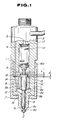
- a fuel injector includes a nozzle body 1 having at an end portion a plurality of injection orifices 2.
- a nozzle holder 3 is arranged in line with the nozzle body 1 and has a pressurized fuel passage 4 and a return passage 5.
- a distance piece 6 is interposed between the nozzle body 1 and the nozzle holder 3.
- the nozzle body 1 and the distance piece 6 is fastened to the nozzle holder 3 by means of a holder nut 7.
- the nozzle body 1 is a hollow and has an inner circumferential surface 1a at the other end portion opposite to the end portion formed with the injection orifices 2.
- An auxiliary sleeve 8 which is generally cylindrical is installed in the nozzle body 1 for sliding movement on the inner circumferential surface 1a of the nozzle body 1.
- a needle valve 9 is concentrically installed in the nozzle body 1 and partly received by the auxiliary sleeve 8 for sliding movement on an inner circumferential surface 8b of the auxiliary sleeve 8.
- a nozzle spring 10 is provided for urging the needle valve 9 toward the nozzle body end portion formed with the injection orifices 2, i.e., in the valve closing direction by way of a push rod 11.
- the auxiliary sleeve 8 is reduced in outer diameter at an end portion nearer to the injection orifices 2 to provide a radially inwardly extending shoulder 8c while the inner circumferential surface 1a is reduced in diameter at an end portion to provide a radially inwardly extending stopper 12 upon which the shoulder 8c of the auxiliary sleeve 8 is capable of abutting and thereby preventing further movement of the auxiliary sleeve 8 toward the injection orifices 2, i.e., in the direction corresponding to that in which the needle valve 9 is moved to contact a conical or tapered seat 1b of the injector body 1 to close the fuel injector.
- a clearance "l” is provided between the other end of the auxiliary sleeve 8 and the distance piece 6 when the shoulder 8c is in contact with the stopper 12.
- the auxiliary sleeve 8 is capable of abutting upon the distance piece 6 through movement over the distance "l” and thus limited in movement toward the distance piece 6, i.e., in movement in the direction corresponding to that in which the needle valve 9 moves to open the fuel injector.
- the reciprocative stroke of the auxiliary sleeve 8 is set so as to coincide with a predetermined pre-lift "l” .
- the auxiliary sleeve 8 has at an end nearer to the injection orifices 2 a conical or tapered pressure receiving surface 8a constituting part of a wall defining a pressure chamber 13.
- the pressue chamber 13 is annular in shape and formed in the nozzle body 1 in such a way as to concentrically encircle the neele valve 9.
- the pressure chamber 13 is communicated with the pressurized fuel passage 4 of the nozzle holder 3 through a pressurized fuel passage 14 formed in the nozzle body 1 and adapted to be supplied with pressurized fuel from a fuel injection pump (not shown).
- the needle valve 9 has a conical end 9a capable of contacting the conical seat 1b of the nozzle body 11 to obstruct communication between the pressure chamber 13 and the injection ports 2.
- the needle valve 9 has at an axially intermediate portion a conical or tapered pressure receiving surface 9b and at a portion next to the conical end 9a a conical or tapered pressure receiving surface 9c.
- the pressure receiving surface 9b is continuous with the pressure receiving surface 8a of the auxiliary sleeve 8 when the shoulder 8b is in contact with the stopper 12 and adapted to define part of the pressure chamber 13.
- the needle valve 9 has, at an end opposite to the conical end portion 9a, a disk-like flange portion 15 which is arraged outside of the auxiliary sleeve 8 and formed so as to have an outer diameter than is larger than the inner diameter of the auxiliary sleeve 8 and thus capable of abutting upon the corresponding end of the auxiliary sleeve 8 at the time of lifting of the auxiliary sleeve 8.
- the distace piece 6 is formed with a concentric circular recess 16 into which the flage portion 15 is insertable while sliding on the inner circumferential surface of same.
- a shim 17 for adjusting the valve opening pressure.
- the auxiliary sleeve 8 When the needle valve 9 and the auxiliary sleeve 8 performs the pre-lift "l" , the auxiliary sleeve 8 abuts upon the distance piece 6. In this instance, the flange portion 15 of the needle valve 9 is out of contact with the bottom surface 16a of the recess 16 so that the needle valve 9 is solely liftable further. From this stage onward, only the pressure receiving surfaces 9b, 9c of the needle valve 9 are thus effective for driving the needle valve 9. Since a relatively smaller pressure receiving surface is obtained for driving the needle valve 9 as compared with that during the pre-lifting, the needle valve 9 stops lifting once when it is raised the pre-lift "l” as shown in Fig. 2 and remains in the standstill condition when the fuel pressure ranges from P1 to P2.
- the needle valve 9 When the fuel pressure increases further to cause the force acting on the pressure receiving surfaces 9a-9c of the needle valve 9 to exceed beyond the valve opening pressure given by the nozzle spring 10, the needle valve 9 solely starts lifting further and keeps on same until it raised the maximum lift "L" whereupon the flange portion 15 abuts upon the bottom surface 16a of the recess 16.
- the fuel injector of the present invention can reduce the number of constitutent parts and therefore the cost.
- valve opening pressure can be attained by an easy adjusting work of the single nozzle spring 10, thus making it possible to increase the working efficiency.
- pre-lift “l” and the maximum lift “L” are determined by the clearance between the needle valve 9 and the distance piece 6 and the clearance between the auxiliary valve 8 and the distance piece 6, respectively, thus making it possible to control their accuracies with ease and attain their repairments before they are installed in place, and therefore making it possible to attain an improved working efficiency.
- Fig. 4 shows another embodiment which is adapted to vary the fuel injecting directions, etc. by using the above described stepwisely varing lift.
- the nozzle body 1 has a relatively large domed end portion 21 including a cylindrical inner circumferential surface 22.
- the domed end portion 21 has adjacent the terminal end a single or a plurality of first injection orifices 24.
- the nozzle body 1 has next to the inner circumferential surface 22 a conical or tapered seat 23 on which the needle valve 9 rests.
- a plurality of second injection orifices 25 are formed in a conical or tapered wall portion of the nozzle body 1 defining the seat 23 and adjacent the smaller diameter end of same.
- the needle valve 9 has at a terminal end a throttle pin 26 which slides on the the inner circumerential surface 22.
- the thottle pin 26 is of such a length that corresponds to the above described pre-lift "l" when the conical end portion 9a rests on the seat 23.
- the throttle pin 26 keeps obstructing communicating between the inside of the domed end portion 21 and the pressure chamber 13, thus allowing fuel to be injected only through the second injection orifices 25.
- the throttle pin 26 allows to communicate the inside of the domed end portion 21 and the pressure chabmer 13, thus allowing fuel to be injected through both the first injection orifices 24 and the second injection orifices 25.
Landscapes
- Engineering & Computer Science (AREA)
- Chemical & Material Sciences (AREA)
- Combustion & Propulsion (AREA)
- Mechanical Engineering (AREA)
- General Engineering & Computer Science (AREA)
- Fuel-Injection Apparatus (AREA)
Claims (7)
- Kraftstoff-Einspritzvorrichtung, mit- einem Düsenkörper (1) mit einer Einspritzöffnung (2) an einem Endbereich und einer inneren Umfangsfläche (1a) am anderen Endbereich,- einer im wesentlichen zylindrischen Hülse (8) in dem Düsenkörper, die auf der inneren Umfangsfläche (1a) gleitet,- einem Nadelventil (9), das beweglich in der Hülse (8) angeordnet ist und die Zufuhr von Druckfluid zu der Einspritzöffnung steuert, welches Nadelventil (9) eine Druckaufnahmefläche (9b) aufweist, die dem Kräftstoffdruck ausgesetzt ist und das Nadelventil in die eine Richtung drückt,- einer Federeinrichtung (10), die das Nadelventil in die entgegengesetzte Richtung drückt,- einer ersten Anschlageinrichtung (8,6) zur Begrenzung der Bewegung der Hülse (8) in bezug auf den Düsenkörper (1) auf einen ersten beweglichen Bereich (ℓ),- einer zweiten Anschlageinrichtung (15,16a) zur Begrenzung der Bewegung des Nadelventils (9) in bezug auf den Düsenkörper (1) auf einen zweiten beweglichen Bereich (L), der größer als der erste bewegliche Bereich (ℓ) ist,- einer Eingriffseinrichtung (8, 15) zum Verbinden des Nadelventils (9) und der Hülse (8) und damit zum Ermöglichen einer gemeinsamen Bewegung zur Zeit der Bewegung der Hülse innerhalb des ersten beweglichen Bereichs (ℓ),- welche Eingriffseinrichtung einen Flanschbereich (15) umfaßt, der an einem Ende des Nadelventils (9) außerhalb der Hülse (8) vorgesehen ist, wobei ein Endbereich der Hülse (8) mit dem Flanschbereich (15) anschlagend in Eingriff zu bringen ist, und- einem Distanzstück (6) an dem Endbereich der Hülse,
dadurch gekennzeichnet, daß die erste Anschlageinrichtung einen Bereich reduzierten Durchmessers umfaßt, der am anderen Endbereich der Hülse (8) vorgesehen ist und eine Schulter (8c) bildet, daß ein reduzierter Durchmesserbereich in einem Endbereich der inneren Umfangsfläche (1a) vorgesehen ist und auf diese Weise einen Anschlag (12) bildet, gegen den die Schulter (8c) unter der Vorspannkraft der Federeinrichtung (10) anschlägt, und daß der Endbereich der Hülse (8) in einem Abstand von dem Distanzstück (6) liegt, der dem ersten beweglichen Bereich (ℓ) entspricht, wenn die Schulter (8c) der Hülse (8) gegen den Anschlag (12) anschlägt. - Kraftstoff-Einspritzvorrichtung nach Anspruch 1, dadurch gekennzeichnet, daß die zweite Anschlageinrichtung einen abgeschrägten Sitz (16) umfaßt, der an einem Endbereich des Düsenkörpers (1) angrenzend an die Einspritzöffnung (2) vorgesehen ist, daß ein abgeschrägter Endbereich (9c) am anderen Ende des Nadelventils (9) vorgesehen ist, der zum anschlagenden Zusammentreffen mit dem Sitz dient, daß eine Ausnehmung (16) in dem Distanzstück (6) ausgebildet ist, die eine Bodenfläche (16a) aufweist, daß der Flanschbereich ( 15) des Nadelventils beweglich in der Ausnehmung angeordnet ist und eine Endfläche aufweist, die in einem Abstand von der Bodenfläche der Ausnehmung liegt, der dem zweiten beweglichen Bereich (L) entspricht, wenn der schräge Bereich des Nadelventils anschlagend mit dem Sitz des Düsenkörpers (12) in Eingriff tritt.
- Kraftstoff-Einspritzvorrichtung nach Anspruch 2, dadurch gekennzeichnet, daß der Düsenkörper (9) weiterhin eine Druckkammer ( 13) in der Nähe der inneren Umfangsfläche aufweist, die unter Druck stehenden Kraftstoff aufnimmt, welche Druck aufnehmende Fläche (8a) der Hülse (8) so angeordnet ist, daß sie ein Teil der Druckkammer bildet, daß die Druck aufnehmende Fläche (9b) des Nadelventils (9) einen Flächenbereich aufweist, der in einem axialen Mittelbereich des Nadelventils angeordnet ist und einen Teil der Druckkammer bildet, daß die Druck aufnehmende Fläche der Hülse und der Druck aufnehmende Flächenbereich des Nadelventils kontinuierlich zueinander verlaufen, wenn die Hülse und das Nadelventil in anschlagendem Eingriff mit dem Anschlag und dem Sitz stehen.
- Kraftstoff-Einspritzvorrichtung nach Anspruch 3, dadurch gekennzeichnet, daß die Vorrichtung einen Düsenhalter (3) in Reihe mit dem Düsenkörper (1) umfaßt, welches Distanzstück (6) zwischen den Düsenkörper und dem Düsenhalter liegt, und daß eine Haltemutter (7) den Düsenkörper und das Distanzstück an dem Düsenhalter befestigt.
- Kraftstoff-Einspritzvorrichtung nach Anspruch 4, dadurch gekennzeichnet, daß die Federeinrichtung (10) eine einzelne Feder umfaßt, die in Reihe mit dem Nadelventil (9) angeordnet ist und in dem Düsenhalter (3) aufgenommen ist.
- Kraftstoff-Einspritzvorrichtung nach Anspruch 5, dadurch gekennzeichnet, daß die Federeinrichtung (10) weiterhin eine Schubstange (11) umfaßt, die zwischen einem Ende der Feder und dem Flanschbereich (15) des Nadelventils (9) liegt, und eine Unterlegscheibe (17) zwischen dem anderen Ende der Feder und einer entsprechenden Sitzfläche an dem Düsenhalter.
- Kraftstoff-Einspritzvorrichtung nach Anspruch 1, dadurch gekennzeichnet, daß der Düsenkörper (1) einen kuppelförmigen Endbereich (21) umfaßt, der mit der Einspritzöffnung (2) versehen ist, daß der kuppelförmige Endbereich eine zylindrische innere Umfangsfläche (22) aufweist, daß der Düsenkörper weiterhin einen abgeschrägten Wandbereich aufweist, der einen abgeschrägten Sitz (23) angrenzend an die zylindrische innere Umfangsfläche bildet, daß der abgeschrägte Wandbereich mit einer Anzahl von zweiten Einspritzöffnungen (25) versehen ist, daß das Nadelventil (9) einen abgeschrägten Endbereich aufweist, der anschlagend mit dem Sitz in Eingriff tritt und die Zufuhr von unter Druck stehendem Kraftstoff zu den zweiten Einspritzöffnungen steuert, und daß das Nadelventil an einem Ende einen zylindrischen Drosselstift (26) aufweist, der von dem abgeschrägten Endbereich vorspringt und gleitend auf der inneren Umfangsfläche des kuppelförmigen Endbereichs zur Steuerung der Zufuhr von Kraftstoff zu der ersten Einspritzöffnung beweglich ist.
Applications Claiming Priority (2)
| Application Number | Priority Date | Filing Date | Title |
|---|---|---|---|
| JP19078388A JPH0240078A (ja) | 1988-07-30 | 1988-07-30 | 内燃機関の燃料噴射弁 |
| JP190783/88 | 1988-07-30 |
Publications (3)
| Publication Number | Publication Date |
|---|---|
| EP0353657A2 EP0353657A2 (de) | 1990-02-07 |
| EP0353657A3 EP0353657A3 (en) | 1990-09-19 |
| EP0353657B1 true EP0353657B1 (de) | 1993-01-20 |
Family
ID=16263663
Family Applications (1)
| Application Number | Title | Priority Date | Filing Date |
|---|---|---|---|
| EP19890113992 Expired - Lifetime EP0353657B1 (de) | 1988-07-30 | 1989-07-28 | Kraftstoffeinspritzventil |
Country Status (3)
| Country | Link |
|---|---|
| EP (1) | EP0353657B1 (de) |
| JP (1) | JPH0240078A (de) |
| DE (1) | DE68904496T2 (de) |
Families Citing this family (3)
| Publication number | Priority date | Publication date | Assignee | Title |
|---|---|---|---|---|
| DE19518950B4 (de) * | 1994-05-23 | 2007-03-29 | Nissan Motor Co., Ltd., Yokohama | Kraftstoffeinspritzdüse |
| RU2136947C1 (ru) * | 1997-09-02 | 1999-09-10 | ОАО Ярославский завод дизельной аппаратуры | Топливовпрыскивающая форсунка для системы питания двс |
| CN118167524B (zh) * | 2024-03-28 | 2024-10-29 | 聊城科瑞汽车零部件有限公司 | 一种喷油嘴总成及其加工设备 |
Family Cites Families (5)
| Publication number | Priority date | Publication date | Assignee | Title |
|---|---|---|---|---|
| DE581476C (de) * | 1931-11-15 | 1933-07-28 | Robert Bosch Akt Ges | Fluessigkeitsgesteuerte Einspritzduese |
| FR2050592A5 (de) * | 1969-06-18 | 1971-04-02 | Ffsa | |
| DE2555019A1 (de) * | 1975-12-06 | 1977-06-16 | Bosch Gmbh Robert | Kraftstoffeinspritzventil fuer vor- und haupteinspritzung |
| GB8704258D0 (en) * | 1987-02-24 | 1987-04-01 | Lucas Ind Plc | Fuel injection nozzle |
| GB2215397A (en) * | 1988-02-26 | 1989-09-20 | Lucas Ind Plc | I.C. engine fuel injection nozzle |
-
1988
- 1988-07-30 JP JP19078388A patent/JPH0240078A/ja active Pending
-
1989
- 1989-07-28 EP EP19890113992 patent/EP0353657B1/de not_active Expired - Lifetime
- 1989-07-28 DE DE1989604496 patent/DE68904496T2/de not_active Expired - Fee Related
Also Published As
| Publication number | Publication date |
|---|---|
| EP0353657A2 (de) | 1990-02-07 |
| DE68904496T2 (de) | 1993-08-12 |
| JPH0240078A (ja) | 1990-02-08 |
| EP0353657A3 (en) | 1990-09-19 |
| DE68904496D1 (de) | 1993-03-04 |
Similar Documents
| Publication | Publication Date | Title |
|---|---|---|
| EP0393590B1 (de) | Brennstoffeinspritzeinrichtung für Dieselmotoren | |
| EP0449763B1 (de) | Kraftstoffeinspritzdüse | |
| US4662338A (en) | Fuel injection nozzle | |
| US5464156A (en) | Electromagnetic fuel injection valve | |
| US6145492A (en) | Control valve for a fuel injection valve | |
| US5020500A (en) | Hole type fuel injector and injection method | |
| US4407457A (en) | Fuel injection nozzle for internal combustion engines | |
| US6247452B1 (en) | Fuel injection valve for internal combustion engines | |
| US4528951A (en) | Fuel injection valve for internal combustion engines | |
| US4635854A (en) | Fuel injection valve for internal combustion engines | |
| US4909444A (en) | Poppet covered orifice fuel injection nozzle | |
| US4096999A (en) | Fuel injection valve for preliminary and principal injection | |
| US6896208B2 (en) | Fuel injection system for an internal combustion engine | |
| US4258883A (en) | Fuel injection nozzle | |
| US4669668A (en) | Fuel injector for internal combustion engines | |
| US6213093B1 (en) | Hydraulically actuated electronic fuel injection system | |
| EP0283154A1 (de) | Brennstoffeinspritzdüse | |
| GB2318152A (en) | I.c. engine fuel-injection valve with controllable two-stage opening stroke | |
| US5660331A (en) | Fuel supply system | |
| US20010054651A1 (en) | Fuel injector with a control rod controlled by the fuel pressure in a control chamber | |
| EP0353657B1 (de) | Kraftstoffeinspritzventil | |
| US6543706B1 (en) | Fuel injection nozzle for an internal combustion engine | |
| US4836454A (en) | Fuel injection nozzles | |
| US4730785A (en) | Fuel injection nozzle for internal combustion engines | |
| US6953157B2 (en) | Fuel injection device for an internal combustion engine |
Legal Events
| Date | Code | Title | Description |
|---|---|---|---|
| PUAI | Public reference made under article 153(3) epc to a published international application that has entered the european phase |
Free format text: ORIGINAL CODE: 0009012 |
|
| 17P | Request for examination filed |
Effective date: 19890728 |
|
| AK | Designated contracting states |
Kind code of ref document: A2 Designated state(s): DE GB |
|
| PUAL | Search report despatched |
Free format text: ORIGINAL CODE: 0009013 |
|
| AK | Designated contracting states |
Kind code of ref document: A3 Designated state(s): DE GB |
|
| 17Q | First examination report despatched |
Effective date: 19910618 |
|
| GRAA | (expected) grant |
Free format text: ORIGINAL CODE: 0009210 |
|
| AK | Designated contracting states |
Kind code of ref document: B1 Designated state(s): DE GB |
|
| REF | Corresponds to: |
Ref document number: 68904496 Country of ref document: DE Date of ref document: 19930304 |
|
| PLBE | No opposition filed within time limit |
Free format text: ORIGINAL CODE: 0009261 |
|
| STAA | Information on the status of an ep patent application or granted ep patent |
Free format text: STATUS: NO OPPOSITION FILED WITHIN TIME LIMIT |
|
| 26N | No opposition filed | ||
| PGFP | Annual fee paid to national office [announced via postgrant information from national office to epo] |
Ref country code: GB Payment date: 19940719 Year of fee payment: 6 |
|
| PGFP | Annual fee paid to national office [announced via postgrant information from national office to epo] |
Ref country code: DE Payment date: 19940721 Year of fee payment: 6 |
|
| PG25 | Lapsed in a contracting state [announced via postgrant information from national office to epo] |
Ref country code: GB Effective date: 19950728 |
|
| GBPC | Gb: european patent ceased through non-payment of renewal fee |
Effective date: 19950728 |
|
| PG25 | Lapsed in a contracting state [announced via postgrant information from national office to epo] |
Ref country code: DE Effective date: 19960402 |