EP0353664A2 - Vorrichtung zum Ausschneiden von dünnen Filmen - Google Patents
Vorrichtung zum Ausschneiden von dünnen Filmen Download PDFInfo
- Publication number
- EP0353664A2 EP0353664A2 EP89114022A EP89114022A EP0353664A2 EP 0353664 A2 EP0353664 A2 EP 0353664A2 EP 89114022 A EP89114022 A EP 89114022A EP 89114022 A EP89114022 A EP 89114022A EP 0353664 A2 EP0353664 A2 EP 0353664A2
- Authority
- EP
- European Patent Office
- Prior art keywords
- frame
- cutting
- cutter
- appliance
- magnifying glass
- Prior art date
- Legal status (The legal status is an assumption and is not a legal conclusion. Google has not performed a legal analysis and makes no representation as to the accuracy of the status listed.)
- Withdrawn
Links
Images


Classifications
-
- B—PERFORMING OPERATIONS; TRANSPORTING
- B26—HAND CUTTING TOOLS; CUTTING; SEVERING
- B26B—HAND-HELD CUTTING TOOLS NOT OTHERWISE PROVIDED FOR
- B26B27/00—Hand cutting tools not provided for in the preceding groups, e.g. finger rings for cutting string, devices for cutting by means of wires
-
- B—PERFORMING OPERATIONS; TRANSPORTING
- B26—HAND CUTTING TOOLS; CUTTING; SEVERING
- B26F—PERFORATING; PUNCHING; CUTTING-OUT; STAMPING-OUT; SEVERING BY MEANS OTHER THAN CUTTING
- B26F1/00—Perforating; Punching; Cutting-out; Stamping-out; Apparatus therefor
- B26F1/38—Cutting-out; Stamping-out
- B26F1/3806—Cutting-out; Stamping-out wherein relative movements of tool head and work during cutting have a component tangential to the work surface
- B26F1/3813—Cutting-out; Stamping-out wherein relative movements of tool head and work during cutting have a component tangential to the work surface wherein the tool head is moved in a plane parallel to the work in a coordinate system fixed with respect to the work
Definitions
- the present invention relates to a thin film cutting appliance used for making cut-out masks for photoengraving.
- a colored translucent plastic thin film is overlaid on a photograph, which constitutes an original.
- the portion of the film which has the same size as the outline of the photograph is cut along the outline by a cutter so as to be used for subsequent design applications.
- a film coated with a light-blocking thin film is overlaid on a photograph, which constitutes an original, and the portion of the thin film, which has the same size as the outline of the photograph, is cut along the outline by a cutter.
- Each of the cutters is shaped like a stencil pen and held by the operator. It requires a substantial amount of skill to maintain each of the cutters at the prescribed angles, and since the inclination of the cutting edge of the cutter always changes, it makes it difficult to accurately cut the thin film.
- the appliance has a frame shaped as a short cylinder or pipe and a level bottom end which is placed on a film coated with a light-blocking thin film.
- the level end is the bottom of the frame and the frame is then moved so that a portion of the thin film, which has a desired size, it cut out along the outline of a photograph by a cutter mounted inside the frame.
- the cutter 4′ is hung on a support arm 3′ so as to extend down in the cylindrical frame 1′ and is always urged downward by a plate spring 5′ attached to the support arm.
- a plate spring 5′ attached to the support arm.
- the cylindrical frame 1′ limits the field of vision, it is often difficult to properly align the cutting edge of the cutter 4′ with respect to the photograph.
- the downward pressure applied to the cutter 4′ by the plate spring 5′ is constant, the cutting force of the cutter cannot be finely controlled like a stencil pen to efficiently cut the thin film.
- the present invention has as an object the solution of the above-mentioned problems. According to the invention, it is possible to always view the cutting edge of a cutter and a portion of a photograph in relation to each other without being affected by the presence of a frame surrounding the cutter. Also, the downward pressure applied to the cutter is easily controllable.
- the appliance comprises a frame 1, a support arm 3, a cutter 4, an oblique plate 5 and a magnifying lens 6.
- the frame 1 and the oblique plate 5 are made of a transparent plastic.
- the frame 1 is a thick square board and has a circular through opening 2 in the central portion of the frame.
- the support arm 3 is set up on a central part of one of the mutually opposite portions of the frame 1.
- the cutter 4 is hung from the tip of the support arm 3.
- the oblique plate 5 is attached to the other of the mutually opposite portions of the frame 1 at an angle of about 45 thereto.
- the magnifying lens 6 is fitted in the central portion of the oblique plate 5.
- the cutter 4 comprises a cutting member 8 made of a thin wire and provided with a cutting edge 7 at the lower end of the cutting member by obliquely cutting off the wire at one end thereof, a holder 11 coupled to the lower end of a vertically movable rod 10 fitted in a vertical cylinder 9 attached to the support are 3, a viscous fluid such as grease and petrolatum provided between the cutting member and the holder, a spring 12 provided in the vertical cylinder, and a push screw 13.
- the cutting member 8 is inserted in the holder 11 so that the cutting member is supported.
- the height of the cutting edge 7 can be adjusted, by turning the push screw 13, through the action of the spring 12 interposed between the screw and the vertically moveable rod 10.
- the upper end of the cutting member 8 is a needle-like sharp-pointed end 14 movably engaged in a conical recess of the holder 11 so that the cutting member is always lightly rotatably supported non-eccentrically.
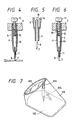
- Fig. 6 is a longitudinal sectional view of a thin film cutting appliance which is a modification of the above-desribed embodiment.
- a small ball 15 is interposed between spring 12 and the push screw 13, so that the screw can be turned more lightly than the appliance shown in Figs. 2, 3, 4 and 5. Otherwise, the appliance shown in Fig. 6 is the same as that shown in Figs. 2, 3, 4 and 5.
- the focal point of the magnifying lens 6 is nearly coincident with the cutting edge 7 of the cutting member 8. Since the diameter of the lens 6 is nearly equal to that of the through opening 2 of the frame 1, the edge of the frame around the opening can hardly be seen through the lens.
- the present invention is not confined thereto but may be otherwise embodied so that the lens is secured to the central portion of the oblique plate by other means such as adhesive bonding.
- the appliance comprises a frame 101, a magnifying lens 103, a cutter 104, and a support member 105.
- the frame 101 and the support member 105 are made of a transparent plastic.
- the frame 101 is made of a pipe having a partially rectangular cross-section and obliquely cut off at an angle of about 45° to the axis of the pipe so that the frame has an opening 102 at the obliquely cut-off end of the frame.
- the other end of the frame 101 is made circular.
- the magnifying lens 103 is fitted in the circular end of the frame 101.
- the cutter 104 is attached with the support member 105 to the frame 101 so that the cutter extends through the peripheral portion of the frame.
- the cutter 104 comprises a cutting member 108 made of a thin wire and provided with a cutting edge 107 at the lower end of the cutting member by obliquely cutting off the wire at one end thereof, a holder 111 coupled to the lower end of a vertically movable rod 110 provided in a vertical cylinder 109 attached to the support member 105, a viscous fluid such as grease and petrolatum provided between the cutting member and the holder, a spring 112 provided in the vertical cylinder, and a push screw 113.
- the cutting member 108 is inserted in the holder 111 so that the member is supported.
- the height of the cutting edge 107 can be adjusted by turning the push screw 113, through the action of the spring 112 interposed between the screw and the vertically movable rod 110.
- the construction and operation of the cutting member 108 are the same as those of the cutting member of the appliance shown in Figs. 2, 3, 4 and 5.
- Fig. 10 is a longitudinal sectional view of a thin film cutting appliance which is a modification of the device shown in Figs. 7, 8 and 9.
- a small ball 115 is interposed between a spring 112 and a push screw 113 so that the screw can be turned more lightly than in the appliance shown in Figs. 7, 8 and 9.
- the appliance shown in Fig. 10 is the same as that shown in Figs. 7, 8 and 9.
- the magnifying lens 103 is attached to the frame 101 at an angle of about 45 thereto so that the focal point of the lens is nearly coincident with the cutting edge 107 of the cutter 108. Since the diameter of the lens 103 is nearly equal to the distance between the side edges of the the opening 102 of the frame 101, the edge of the frame around the opening can hardly be seen through the lens.
- the lens 103 is secuted to the frame 101 by fitting, the present invention is not confined thereto but may be otherwise embodied so that the lens is secured to the frame by other means such as adhesive bonding.
- Each of the above-described appliances is placed on a film coated with a light-blocking thin film and overlaid on a photograph, so that the magnifying lens faces the operator who manipulates the appliance.
- the push screw of the cutter is turned to adjust the downward pressure applied to the cutting member thereof.
- the cutting edge of the cutter is then caused to cut into the films.
- the whole appliance is held by the fingers of the operator so that the appliance is moved over the films. Since the cutting edge is eccentrically located with regard to the axis of the cutting member, the member is automatically turned along with the movement of the appliance so that the cutting edge is always oriented in the direction of the movement.
- the films can be efficiently and easily cut.
- the downward pressure applied to the cutting member can be adjusted by the push screw as occasion demands. Besides, the operator can easily hold the appliance without being likely to suffer injury due to the cutting edge.
Landscapes
- Life Sciences & Earth Sciences (AREA)
- Forests & Forestry (AREA)
- Engineering & Computer Science (AREA)
- Mechanical Engineering (AREA)
- Nonmetal Cutting Devices (AREA)
- Knives (AREA)
Applications Claiming Priority (4)
| Application Number | Priority Date | Filing Date | Title |
|---|---|---|---|
| JP10151788U JPH0224849U (de) | 1988-07-30 | 1988-07-30 | |
| JP10151888U JPH0224850U (de) | 1988-07-30 | 1988-07-30 | |
| JP101518/88U | 1988-07-30 | ||
| JP101517/88U | 1988-07-30 |
Publications (2)
| Publication Number | Publication Date |
|---|---|
| EP0353664A2 true EP0353664A2 (de) | 1990-02-07 |
| EP0353664A3 EP0353664A3 (de) | 1991-05-22 |
Family
ID=26442379
Family Applications (1)
| Application Number | Title | Priority Date | Filing Date |
|---|---|---|---|
| EP19890114022 Withdrawn EP0353664A3 (de) | 1988-07-30 | 1989-07-28 | Vorrichtung zum Ausschneiden von dünnen Filmen |
Country Status (2)
| Country | Link |
|---|---|
| US (1) | US4974324A (de) |
| EP (1) | EP0353664A3 (de) |
Families Citing this family (2)
| Publication number | Priority date | Publication date | Assignee | Title |
|---|---|---|---|---|
| USD321467S (en) | 1988-07-11 | 1991-11-12 | Kimoto & Co., Ltd. | Cutting device for masking film |
| US20040035277A1 (en) * | 2002-08-20 | 2004-02-26 | Hubbs William O. | Track and punch SMR marking device |
Family Cites Families (10)
| Publication number | Priority date | Publication date | Assignee | Title |
|---|---|---|---|---|
| US2524636A (en) * | 1947-11-01 | 1950-10-03 | H P Preis Engraving Machine Co | Cutter for pantograph engraving machines |
| US2730811A (en) * | 1954-04-05 | 1956-01-17 | Jr Noel J Gouldsmith | Center punching assembly |
| US2748474A (en) * | 1954-08-27 | 1956-06-05 | Harry C Brown | Combined scribing and eye-protecting optical system |
| US2810960A (en) * | 1956-07-06 | 1957-10-29 | Quentin S Johnson | Precision engraving instrument |
| US2902760A (en) * | 1956-09-17 | 1959-09-08 | Keuffel & Esser Co | Scribing instrument |
| US3107425A (en) * | 1962-03-07 | 1963-10-22 | Robert I Rentz | Cutting instrument |
| US3339279A (en) * | 1964-07-17 | 1967-09-05 | Robert H Sovar | Hollow engraving point and holder for engraving coated transparent sheets |
| DE3514706A1 (de) * | 1984-07-11 | 1986-01-23 | Rudolf Prof. Dr.-Ing. 4350 Recklinghausen Schweißthal | Vorrichtung insbesondere zum gravieren von gravurfolien |
| US4713886A (en) * | 1986-03-17 | 1987-12-22 | Takashi Ikeda | Piercing tool |
| JPH0624836Y2 (ja) * | 1988-07-07 | 1994-06-29 | 邦男 諸角 | 切抜マスク作成用切刻装置 |
-
1989
- 1989-07-28 US US07/386,188 patent/US4974324A/en not_active Expired - Fee Related
- 1989-07-28 EP EP19890114022 patent/EP0353664A3/de not_active Withdrawn
Also Published As
| Publication number | Publication date |
|---|---|
| US4974324A (en) | 1990-12-04 |
| EP0353664A3 (de) | 1991-05-22 |
Similar Documents
| Publication | Publication Date | Title |
|---|---|---|
| US5425665A (en) | Optical lens blocker and method | |
| US4190322A (en) | Magnifying means | |
| EP0137879A2 (de) | Augentropfer mit Lichtquelle | |
| US4103430A (en) | Viewing device for a bubble level | |
| EP0349964A2 (de) | Vorrichtung zum Ausschneiden von Maskenfilmen | |
| US4974324A (en) | Appliance for cutting out thin film | |
| GB2054898A (en) | Support for an optical device | |
| US4977675A (en) | Apparatus for marking eyeglass lens blanks | |
| JP2002283202A (ja) | カップ取付け装置 | |
| US4227349A (en) | Precision blocking of lens blank | |
| US4076391A (en) | Magnifying reading device and viewer | |
| CN220399708U (zh) | 一种光学镜片调整架 | |
| US4995300A (en) | Lathe for generating aspherical surfaces on work pieces | |
| FI60453B (fi) | Avmaskningsanordning foer diapositiv | |
| US4147411A (en) | Device for use in threading needles | |
| US3368285A (en) | Lens marking device | |
| CA1115047A (en) | Double clip lettering guide adjustment wedge | |
| US4347958A (en) | Apparatus for cutting glass | |
| US4494836A (en) | Device for determining and measuring monocular pupillary deviations in a patient's eyes | |
| US4268135A (en) | Image focusing apparatus | |
| US4420911A (en) | Work piece holder assembly | |
| EP4124409A1 (de) | Vorrichtung und verfahren zum anbringen eines linsenblocks | |
| CN217310815U (zh) | 一种青光眼手术用的巩膜制瓣刀 | |
| US2227835A (en) | Punching machine | |
| CN211928877U (zh) | 物理实验光折射演示装置 |
Legal Events
| Date | Code | Title | Description |
|---|---|---|---|
| PUAI | Public reference made under article 153(3) epc to a published international application that has entered the european phase |
Free format text: ORIGINAL CODE: 0009012 |
|
| AK | Designated contracting states |
Kind code of ref document: A2 Designated state(s): CH DE FR GB IT LI |
|
| 17P | Request for examination filed |
Effective date: 19900420 |
|
| PUAL | Search report despatched |
Free format text: ORIGINAL CODE: 0009013 |
|
| AK | Designated contracting states |
Kind code of ref document: A3 Designated state(s): CH DE FR GB IT LI |
|
| 17Q | First examination report despatched |
Effective date: 19930128 |
|
| STAA | Information on the status of an ep patent application or granted ep patent |
Free format text: STATUS: THE APPLICATION IS DEEMED TO BE WITHDRAWN |
|
| 18D | Application deemed to be withdrawn |
Effective date: 19930608 |