EP0353685A2 - Voiture d'enfant - Google Patents
Voiture d'enfant Download PDFInfo
- Publication number
- EP0353685A2 EP0353685A2 EP89114090A EP89114090A EP0353685A2 EP 0353685 A2 EP0353685 A2 EP 0353685A2 EP 89114090 A EP89114090 A EP 89114090A EP 89114090 A EP89114090 A EP 89114090A EP 0353685 A2 EP0353685 A2 EP 0353685A2
- Authority
- EP
- European Patent Office
- Prior art keywords
- seat
- chassis
- footrest
- drawbar
- stroller according
- Prior art date
- Legal status (The legal status is an assumption and is not a legal conclusion. Google has not performed a legal analysis and makes no representation as to the accuracy of the status listed.)
- Withdrawn
Links
Images


Classifications
-
- B—PERFORMING OPERATIONS; TRANSPORTING
- B62—LAND VEHICLES FOR TRAVELLING OTHERWISE THAN ON RAILS
- B62B—HAND-PROPELLED VEHICLES, e.g. HAND CARTS OR PERAMBULATORS; SLEDGES
- B62B7/00—Carriages for children; Perambulators, e.g. dolls' perambulators
- B62B7/02—Carriages for children; Perambulators, e.g. dolls' perambulators having only a single wheel axis
Definitions
- the invention relates to a stroller of the type specified in the preamble of claim 1.
- Such a stroller is known from DE-A-34 34 502.
- This known stroller has the shape of a single-axle, two-wheeled pushchair, with a seat shell with side walls and backrest being arranged on the wheel axle, and also with a centrally attached rod drawbar with transverse handles. Since on the one hand the wheel axle is attached directly to the seat shell and on the other hand the rod drawbar is attached to the wheel axle, the rod drawbar runs out directly under the seat, so that space is only available on both sides next to the drawbar for the two-part footrest. The lower legs of the child sitting in the car must therefore find space on both sides next to the drawbar, which on the other hand means that the drawbar is a hindrance for the toddler when getting on or off the car.
- the invention is therefore based on the object to improve a stroller of the type specified, Dar with simple training and manufacture of the car on this the condition should be created that the seat and footrest area of the drawbar can be used unhindered despite their seat-side arrangement and that this should have a certain suspension comfort despite simple training.
- This object is achieved with a stroller of the type mentioned according to the invention by the features stated in the characterizing part of the main claim. Advantageous further developments result from the subclaims.
- a chassis 1 provided with a wheel axle 10, on which a seat with a seating surface 3 and a footrest 5, which is delimited laterally by armrests 2 and a backrest 4, and a drawbar 6 are arranged on the footrest side.
- 1 is designed such that the backrest support 7, the armrests 2 and the Radacharrier 8 of the chassis 1 from a bracket-like in the area of the backrest 4, loop-like in the area of the armrests 2 and 8-shaped in the area of the Radacharrier bent single tube 9 consist of limited elastic material.
- the drawbar 6 is arranged on the frame side under the footrest 5, as is readily apparent from FIGS. 1 and 3, ie the drawbar 6, which, as indicated by dashed lines in FIG.
- the tube 9 is bent and guided so that it runs from the area of the bow-shaped backrest support 7 on both sides into the armrest loops 12, runs past the armrest loops 12 and is bent in an S-shape on both sides below the ends with the Radacharrimaschine 8.
- This pipe routing is particularly advantageous in that it makes the actual seat 3 easy to attach.
- the seat 3 is arranged with respect to the wheel axle 10 and the detection end 6 'of the drawbar 6 between them just before the wheel axle 10. This ensures that the car with the child inside cannot turn over and the child can fall on its head.
- the entire undercarriage is given a relatively high degree of elasticity, which gives the stroller good suspension comfort without having to be associated with special spring elements.
- the S-shaped design of the Radacharrimaschine 8 leads to the fact that the wheel axle 10 has a sufficient distance to the actual seat 3, which makes it possible to arrange the remote access end of the drawbar 6 under the footrest 5, ie, the stroller can be from hitting child without disability can easily be climbed and left again by the drawbar 6.
- the two lateral tubing strings 9 ' can be connected at the top in the area of the backrest support 7 and in the area of the armrest loops 12' with a bow tie, which can be welded, correspondingly long pieces of pipe.
- the backrest support 7 can be formed as a separate pipe bend part 7 ', which can be inserted with its free ends 7' into the two free ends 12 'of the two armrest loops 12, as from Fig. 2 recognizable.
- the footrest 5 can be arranged at a corresponding distance from the seat surface and can be designed in the form of a shell 14, which is then at the lower region of the wheel axle support parts 8 the chassis is arranged.
- This cup-shaped footrest 5 also ensures a corresponding cross bracing of the wheel axle parts 8 or the entire chassis in the lower region.
- wheel axle holders 23 are provided, which can be made of plastic and which have a through hole for the end regions 11 of the tubular cable 9 and furthermore penetration holes extending transversely thereto for receiving the wheel axle 10. Wing screws 25 are seated in a threaded hole 24 (see FIG. 2) , with which the wheel axle holder 23 can be releasably fixed to the end regions 11 of the wheel axle support parts 8.
- the seat surface 3 and the backrest 4 in the form of two shells 15 or also a single, correspondingly winch-shaped shell and to provide these on the frame side with fastening elements 21 which can be locked on the pipe pull 9 according to FIG. 5 , so that this shell 15 or the corresponding backrest shell and seat shell can be fixed by snapping on the relevant areas of the tubular cable 9.
- this shell 15 or the corresponding backrest shell and seat shell can be fixed by snapping on the relevant areas of the tubular cable 9.
- the entire shell 15 or the seat shell so that the footrest 5 is integrally formed as an integral part 15 ', as indicated by dashed lines in Fig. 3.
- the embodiment according to FIG. 4 differs from the previously described embodiment in that the backrest 4, the seat surface 3 and the radach member parts 8 are combined into one unit while maintaining the advantageous suspension principle, the radach member parts 8 forming a u-shaped bracket 17 , on the lower leg 18 of the wheel axle 10 and the remote end 6 ⁇ of the drawbar 6 are arranged, which is also arranged here running out under the footrest 5.
- Such a design requires a corresponding molding tool for the formation of this entire shell, on which, as can be seen from FIG. 4, the footrest 5 can also be molded on directly.
- shell-side part 19 of the drawbar 6 is expediently designed in the form of a fork in order to facilitate the tilt-proof arrangement of the entire shell according to FIG. 4 and at the same time to obtain freely available ends 11 for the attachment of the wheel axle holder 23, as described above, provided that the wheel axle 10 in this manner to be fixed and attached to the free ends 11.
- the relevant shell part (shaped piece 16 / shell 15) is provided with tab-like extensions 16 'which form the suitable armrests or which overlap the corresponding pipe strands of the armrest loops 12 according to FIGS. 1, 2.
- the entire shell can also be formed in two parts in the interests of extensive dismantling, it only being necessary to ensure that the parts (backrest 4, seat surface 3, wheel carrier parts 8) are securely but releasably connected to one another can.
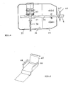
- the chassis 1 consists of hollow profiles in the form of a longitudinal central spar 30 with a transverse spar 31 arranged in the region of the center of the seat M, on or in which the wheel axle 10 for the wheels 32 is resiliently mounted is, on which chassis 1 with at least three support elements 33, the foot support and seat support surface 34 is mounted.
- the longitudinal central spar 30 and the transverse spar 31 are formed from light metal square profiles.
- the longitudinal central spar 30 extends beyond the cross spar 33 to below the rear edge 36 of the wing 34.
- the simple and commercially available Supporting elements 33 designed in the form of vibrating metal elements are also arranged at the ends of the cross member 31.
- a further support element 34 can also be provided under the front edge region of the seat support part 35, but this is not absolutely necessary, since the foot support part 36 rests directly on the longitudinal central spar 30.
- the wing 34 has a conceivably simple cut and, as can be seen from FIG. 1, is to be provided with an offset 37 only in the central region if the extension plane of the seat support part 35 is to be higher than that of the footrest part 36.
- a foot abutment surface 37 is arranged on the footrest part 36 so as to be adjustable in distance from the seat part 35.
- the crossbar 31, which is rigidly connected to the longitudinal central beam 30, is now used to form a resilient wheel axle, as can be seen in FIG. 7. 6, 7, two execution forms are shown in the form of oscillating axes.
- a leaf spring-loaded lever 38 is simply articulated in the cross member 31, at the outer end of which the wheel 32 is then rotatably mounted in a suitable manner.
- the somewhat more complex oscillation axis design is shown on the right in FIG. 7 and consists of a bow-like steering knuckle 39, between which and the cross bar 31, as can be seen better from FIG. 8, oscillating metal elements 40 are arranged.
- a seat holder 43 is provided on each of the two long sides of the support surface 34.
- This seat holder 43 consists of a bracket 44 arranged on the seat support part 35, to which the actual seat holder 43 is fastened releasably by means of a wing nut 45, with which the child seat is held on the seat support part 35.
- This is usually used in front of such child seats available recess between the armrests 4 and the backrest 43, which is used to accommodate belt guides when arranging such a child seat on the back seat of a car.
- the wing 34 can also be designed in the sense of FIG. 9, the wing 34 being extended at the rear edge and being designed as a backrest holder 47, and the wing 34 in the seating area being bent on both sides with extensions forming arm supports 46 is. On or on this seat shell-like support surface 34, seat and backrest cushions are then only to be attached in a suitable manner.
- the longitudinal center strut 30 for the formation of the cart drawbar 6 is not simply kept correspondingly long, which on the one hand would run counter to the required simple production handling and on the other hand would make it more difficult to carry such a cart in a car, for example, but the drawbar 6 is the front end of the longitudinal center strut 30 releasably assigned, and preferably tilt adjustable, which requires no special explanation or illustration, since suitable means and designs are readily available to fix the tiller 6 with the lever 48 in the desired tilt orientation end 30 'of the longitudinal central spar 30 can.
Landscapes
- Engineering & Computer Science (AREA)
- Chemical & Material Sciences (AREA)
- Combustion & Propulsion (AREA)
- Transportation (AREA)
- Mechanical Engineering (AREA)
- Carriages For Children, Sleds, And Other Hand-Operated Vehicles (AREA)
Applications Claiming Priority (4)
| Application Number | Priority Date | Filing Date | Title |
|---|---|---|---|
| DE19883826381 DE3826381C1 (en) | 1988-08-03 | 1988-08-03 | Pushchair |
| DE3826381 | 1988-08-03 | ||
| DE8907036U | 1989-06-08 | ||
| DE8907036U DE8907036U1 (de) | 1989-06-08 | 1989-06-08 | Kinderwagen |
Publications (2)
| Publication Number | Publication Date |
|---|---|
| EP0353685A2 true EP0353685A2 (fr) | 1990-02-07 |
| EP0353685A3 EP0353685A3 (fr) | 1990-08-22 |
Family
ID=25870786
Family Applications (1)
| Application Number | Title | Priority Date | Filing Date |
|---|---|---|---|
| EP89114090A Withdrawn EP0353685A3 (fr) | 1988-08-03 | 1989-07-31 | Voiture d'enfant |
Country Status (1)
| Country | Link |
|---|---|
| EP (1) | EP0353685A3 (fr) |
Family Cites Families (6)
| Publication number | Priority date | Publication date | Assignee | Title |
|---|---|---|---|---|
| FR587364A (fr) * | 1925-04-17 | |||
| US1524958A (en) * | 1922-10-20 | 1925-02-03 | Transue John | Portable baby carriage |
| US1620281A (en) * | 1925-02-26 | 1927-03-08 | Oyston William Robert | Collapsible baby carriage |
| US2593962A (en) * | 1949-05-21 | 1952-04-22 | Paul L Barker | Child's stroller |
| AT299477B (de) * | 1969-08-06 | 1972-06-26 | Eduard Grohs | Transportgerät für Kinder |
| US4470610A (en) * | 1983-02-25 | 1984-09-11 | Wilson Everett E | Children's safety pull toy |
-
1989
- 1989-07-31 EP EP89114090A patent/EP0353685A3/fr not_active Withdrawn
Also Published As
| Publication number | Publication date |
|---|---|
| EP0353685A3 (fr) | 1990-08-22 |
Similar Documents
| Publication | Publication Date | Title |
|---|---|---|
| EP2476607B1 (fr) | Trottinette pour petits enfants | |
| EP0911009B2 (fr) | Fauteuil roulant avec cadre fermé en trois dimensions | |
| EP0198957B1 (fr) | Chaise roulante pour invalides | |
| EP1277644B1 (fr) | Remorque pour voiture d'enfant | |
| EP1366968B1 (fr) | Voiture d'enfant pliable et/ou voiture de poupée pliable | |
| DE1930891A1 (de) | Verwandelbarer Kindersicherheits-Autositz | |
| DE4213240A1 (de) | Lenkstange, insbesondere fuer zweiraeder, wie fahrraeder | |
| CH692179A5 (de) | Rollstuhl und Sitzmodul für den Rollstuhl, | |
| EP3895969A1 (fr) | Agencement de siège | |
| DE3724242C2 (fr) | ||
| DE29700497U1 (de) | Zweisitziger Kinder-Sportwagen | |
| DE10036997C2 (de) | Als Kinderwagen oder Kinderfahrrad einrichtbares multifunktionales Fahrzeug | |
| DE10008230C2 (de) | Fahrzeugkindersitz/Kinderwagen-Kombination | |
| DE3826381C1 (en) | Pushchair | |
| DE20021368U1 (de) | Motorloses Rollfahrzeug | |
| EP1628868B1 (fr) | Chariot de magasin | |
| EP0911012A2 (fr) | Fauteuil roulant pliable | |
| DE2941186C2 (fr) | ||
| DE10019731A1 (de) | Kinder- oder Puppenwagengestell | |
| DE20010213U1 (de) | Zusatzeinrichtung für einen Schiebewagen für Kinder und/oder Puppen | |
| DE19808015C2 (de) | Kinder- oder Puppenwagengestell | |
| DE2165843A1 (de) | Veränderbarer Kindersitz | |
| DE2636603A1 (de) | Gepaeckbehaelter fuer zusammenklappbare sportkinderwagen | |
| DE2529297A1 (de) | Zusammenklappbarer kinderwagen | |
| DE29822182U1 (de) | Zwillingsfahrzeug |
Legal Events
| Date | Code | Title | Description |
|---|---|---|---|
| PUAI | Public reference made under article 153(3) epc to a published international application that has entered the european phase |
Free format text: ORIGINAL CODE: 0009012 |
|
| AK | Designated contracting states |
Kind code of ref document: A2 Designated state(s): AT BE CH DE ES FR GB IT LI NL |
|
| RBV | Designated contracting states (corrected) |
Designated state(s): ES FR GB IT |
|
| REG | Reference to a national code |
Ref country code: DE Ref legal event code: 8566 |
|
| PUAL | Search report despatched |
Free format text: ORIGINAL CODE: 0009013 |
|
| AK | Designated contracting states |
Kind code of ref document: A3 Designated state(s): ES FR GB IT |
|
| STAA | Information on the status of an ep patent application or granted ep patent |
Free format text: STATUS: THE APPLICATION IS DEEMED TO BE WITHDRAWN |
|
| 18D | Application deemed to be withdrawn |
Effective date: 19910223 |