EP0353731A2 - Anechoischer Raum - Google Patents
Anechoischer Raum Download PDFInfo
- Publication number
- EP0353731A2 EP0353731A2 EP89114262A EP89114262A EP0353731A2 EP 0353731 A2 EP0353731 A2 EP 0353731A2 EP 89114262 A EP89114262 A EP 89114262A EP 89114262 A EP89114262 A EP 89114262A EP 0353731 A2 EP0353731 A2 EP 0353731A2
- Authority
- EP
- European Patent Office
- Prior art keywords
- walls
- wall
- lefthand
- anterior
- waves
- Prior art date
- Legal status (The legal status is an assumption and is not a legal conclusion. Google has not performed a legal analysis and makes no representation as to the accuracy of the status listed.)
- Withdrawn
Links
Images




Classifications
-
- H—ELECTRICITY
- H05—ELECTRIC TECHNIQUES NOT OTHERWISE PROVIDED FOR
- H05K—PRINTED CIRCUITS; CASINGS OR CONSTRUCTIONAL DETAILS OF ELECTRIC APPARATUS; MANUFACTURE OF ASSEMBLAGES OF ELECTRICAL COMPONENTS
- H05K9/00—Screening of apparatus or components against electric or magnetic fields
-
- G—PHYSICS
- G01—MEASURING; TESTING
- G01R—MEASURING ELECTRIC VARIABLES; MEASURING MAGNETIC VARIABLES
- G01R29/00—Arrangements for measuring or indicating electric quantities not covered by groups G01R19/00 - G01R27/00
- G01R29/08—Measuring electromagnetic field characteristics
- G01R29/10—Radiation diagrams of antennas
- G01R29/105—Radiation diagrams of antennas using anechoic chambers; Chambers or open field sites used therefor
Definitions
- This invention relates to an anechoic chamber which is otherwise called, a semi-anechoic chamber, and particularly to an anechoic chamber which is small and capable of being installed within an existing building.
- anechoic chamber The version of the anechoic chamber which is intended to handle those waves from a wave generating source, entering a receiving antenna, and including waves reflected from the ground is called a semi-anechoic chamber.
- anechoic chamber is used exclusively in the narrow sense of the word in referring to the case where the receiving antenna is even prevented from entry of waves reflected on the ground solely for the sake of waves traveling through space.
- anechoic chamber is used in the broad sense of the word in inclusively referring to the above case where the waves reflected on the ground are admitted.
- the conventional anechoic chamber for the purpose of intercepting external waves, has a space for accommodation enclosed therein with wall members of a metallic material and, for the purpose of preventing waves generated in the space for accommodation from being reflected on the wall members, has electromagnetic wave absorbers attached to the inner surfaces of the wall members.
- the electromagnetic wave absorbers which are usable in the conventional anechoic chamber include those called as pyramid type and those called as W type, for example.
- the electromagnetic wave absorber is formed of a carbon powder-containing foamed polyurethane resin in the shape of a quadrangular pyramid and are otherwise called as a resistor type electromagnetic wave absorber.
- the absorber of this type is adapted to effect the absorption of waves by converting the electric energy of waves by the heat-generating function of a resistor into thermal energy and, at the same time, preventing the surfaces of the absorber from reflecting waves. Since the performance of the absorber of this type depends most on the height of the absorber, the absorber has required its height to be set at more than about one third of the wavelength of waves to be absorbed. Depending on the frequency of the waves to be measured, therefore, the absorber is required to have a fairly large height. Further, the attenuated primary reflected waves return to the receiving antenna. For the prevention of this phenomenon, the conventional anechoic chamber is required to form the space for accommodation in amply large dimensions. This requirement at times renders materialization of this conventional anechoic chamber difficult.
- the conventional electromagnetic wave absorber of another type makes use of a ferrite.
- the absorber of this type is producted by molding the ferrite in the shape of a tile and attaching the tile to the surface of a metallic plate.
- This absorber or wave-absorbing member is thought to constitute itself a broad-band resonator which is critically coupled with free space. Though this absorber is allowed to have a small thickness, it has upper and lower limits to the range of frequency in the good absorption of waves.
- An object of this invention is to provide an anechoic chamber which allows reduction in the volume of a space for accommodation and yet prevents primary reflected waves from reaching the receiving antenna, enjoys compactness, and permits accurate measurement of waves of a wide range frequency.
- Another object of this invention is to provide an anechoic chamber which comprises a electromagnetic wave shielding ceiling wall and anterior, posterior, lefthand, and righthand walls invariably inclined and electroconductive screens disposed inside the inclined walls and adapted to form a space for seizing waves in cooperation with the walls.
- a further object of this invention is to provide an anechoic chamber which comprises a multiplicity of wave-absorbing members arranged inside electromagnetic wave intercepting ceiling wall and anterior, posterior, lefthand and righthand walls and adapted to constitute themselves electromagnetic wave absorbing walls severally furnished with inclined inner surfaces.
- an anechoic chamber comprising a floor wall, an anterior and a posterior wall, a lefthand and a righthand wall, and a ceiling wall, and a first space for accommodation defined by the walls, and incorporating in the first space for accommodation a transmission source for radiation of waves and a receiving antenna for receiving the linearly polarization component of the waves radiated by the transmission source,
- anechoic chamber is characterized by the fact that the floor wall, the anterior and posterior walls, the lefthand and righthand walls, and the ceiling wall are formed of a metallic material, at least one of the floor wall, the anterior, posterior, lefthand and righthand walls, and the ceiling wall is disposed as inclined by a stated angle relative to a reference line of the polarization of the receiving antenna, and an electroconductive screen incorporating therein an electroconductive material is disposed inside the inclined wall so as to form a second space for seizing waves with the inclined wall.
- the anechoic chamber of the present invention of the plane waves traveling from a transmission source to a receiving antenna, those which are reflected by the inclined electromagnetic wave intercepting walls fail to reach the receiving antenna. Since the anechoic chamber is provided inside the walls with the electroconductive screens defining a space for seizing waves, it allows reduction in the volume of the space for accommodation and yet permits measurement of the condition of transmission of waves from the transmission source such as for example, a computer while preventing intrusive external waves from interfering with the measurement.
- the waves from the transmission source are not reflected by the wave-intercepting walls before they are passed through the electroconductive screens and part of them are repeatedly reflected and attenuated between the opposed surfaces of the electroconductive screens and the wave intercepting walls, not only the primary reflected waves but also the secondary and subsequent reflected waves fail to reach the receiving antenna.
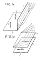
- Fig. 1 A illustrates the fundamental principle of this invention, i.e. the condition in which linearly polarization antennas 1, 2 respectively for transmission and reception are disposed parallelly to each other and vertically relative to a floor wall 3 and waves are transmitted by the transmitting antenna 1 and received by the receiving antenna 2.
- a metallic side wall 4 is disposed parallelly to the antennas 1, 2 so that vertical polarization direct from the transmitting antenna 1 and vertical polarization of primary reflection reflected and attenuated by the floor wall 3 simultaneously reach the receiving antenna 2.
- the anechoic chamber is desired to be such that the space enclosed with metallic walls will be shielded the electromagnetic waves from outside and the reflected waves will be prevented from reaching the receiving antenna 2. It is conceivable that the amount of the reflected waves will be varied by the frequency of the waves, the distance between the two antennas 1, 2, and further by such factors as the distance to the floor walls 3.
- Fig. 1 D illustrates a configuration having a screen 6 disposed on the inside of the side wall 4 attached to the floor wall 3 as separated by a prescribed distance from the side wall.
- This screen 6 is made of a polypropylene resin matrix incorporating therein a wave absorbing material such as carbon powder and, therefore, is vested with electroconductivity.
- the structure of this electroconductive screen 6 is illustrated in detail in Fig. 2. It comprises two sheets 7a, 7b and a plurality of ribbonlike connecting sheets 7c disposed at regular intervals between the two sheets.
- These sheets 7a to 7c are formed of a polypropylene resin matrix incorporating therein carbon powder as an electroconductive material. They jointly define a multiplicity of equal spaces 7d of a tetrahedral cross section.
- the electroconductive screen 6 When the electroconductive screen 6 is set in place parallelly to the side wall 4 which is inclined upwardly as illustrated in Fig. 1 D, the waves from the transmitting antenna 1 are partly reflected by the electroconductive screen 6 and the remainder thereof are passed therethrough. The waves attenuated by this passage are allowed to reach the metallic side wall 4, further attenuated and reflected thereby, and again brought to the electroconductive screen 6. The waves are partly passed therethrough, with the remainder reflected and brought to the side wall again. Thus, a space 80 for seizing the passed waves is formed between the side wall 4 and the electroconductive screen 6.
- the present invention eliminates the reflected wave that are transmitted by the transmission source reflected by any walls and received by the receiving device and consequently maintains the anechoic chamber in a nearly ideal state.
- FIG. 3 and Fig. 4 A to Fig. 4 C are diagrams illustrating embodiments of this invention which is accomplished by the utilization of the nature of reflected waves mentioned above.
- FIGs illustrate basic configurations of the anechoic chamber according with the present invention.
- the walls of the anechoic chambers illustrated in these diagrams are basically equal to those of the anechoic chamber disclosed in Japanese Patent Application SHO 62(1987)-270,257 already filed by the present applicant.
- An anechoic chamber 10 of this invention as illustrated, comprises a floor wall 11, an anterior wall 12, a posterior wall 13, a lefthand wall 14, a righthand wall 15, and a ceiling wall 16 and contains therein a space 17 for accommodation as defined by the walls.
- Fig. 3 and Fig. 4 A to Fig. 4 C are diagrams illustrating embodiments of this invention which is accomplished by the utilization of the nature of reflected waves mentioned above.
- FIGs illustrate basic configurations of the anechoic chamber according with the present invention.
- the ceiling wall 16 is omitted from illustration.
- the walls 11 to 16 mentioned above are invariably formed of wave sheilding plates of such a metallic material as steel. Owing to the structure, the otherwise entry of external waves into the space 17 for accommodation is eliminated.
- a transmission source 21 for radiating waves inside the space 17 for accommodation and a linearly polarization antenna 22 for receiving the linearly polarization component of the waves from the transmission source 21 are disposed on the floor wall 11, a transmission source 21 for radiating waves inside the space 17 for accommodation and a linearly polarization antenna 22 for receiving the linearly polarization component of the waves from the transmission source 21 are disposed.
- the linearly polarization antenna 22 used herein has the shape of a rod and has a reference line 0 of polarization.
- the receiving antenna 22 is set up in place so that the reference line 0 lies in a vertical line. This antenna 22 receives the vertical polarization from the transmission source 21.
- the anterior wall 12 mentioned above, as illustrated in Fig. 3 and Fig. 4 A, is inclined by a stated angle, av, relative to the reference line 0 of the antenna 22.
- the posterior wall 13 is inclined by a stated angle, bv, relative to the reference line 0.
- the lefthand wall 14, as illustrated in Fig. 4 B, is inclined by a stated angle, cv, relative to the reference line 0 of the antenna 22 and the righthand wall 15 is similarly inclined by a stated angle, dv.
- the walls 12 to 15 are inclined upwardly as illustrated.
- the four walls 12 to 15 are inclined upwardly by respectively stated angles relative to the reference line 0 as mentioned above, of the vertical polarization from the transmission source 21, the primary reflection waves reflected by the walls 14, 15 are not allowed in their unaltered form to reach the receiving antenna 22.
- the linearly polarization antenna 22 is set up in a horizontal state inside the space 17 as illustrated in Fig. 3 and Fig. 4 B to permit measurement of horizontal polarization from the transmission source 21.
- the ceiling wall 16 is inclined by a stated angle, eH2, relative to the reference line 0 which will assume a horizontal state in this case. Owing to the inclination of the ceiling wall 16 to be made in the manner mentioned above, even when the measurement of horizontal polarization is made by the use of the receiving antenna 22 having the reference line of polarization 0 in a horizontal state, the primary reflection waves from the ceiling wall 16 is no longer allowed to reach the receiving antenna 22 similarly to the case mentioned above.
- the transmission source 21 is required to be placed closer to the anterior wall 12 and the receiving antenna 22 closer to the posterior wall 13.
- the transmitting antenna 22 is installed in the space 17 accommodation in such a manner that the reference line 0 of polarization of the transmitting antenna 22 is directed in a horizontal line passing through the walls 14, 15.
- the horizontal line is directed perpendicularly to the vertical direction and may be divided into the first horizontal line (X-axis direction) passing through the opposed walls 12, 13 and the second horizontal line (Y-axis direction) passing through the opposed walls 14, 15.
- the first horizontal line is denoted by a numeral of 01 and the second horizontal line by a numeral of 02.
- the lefthand wall 14 and the righthand wall 15 are inclined respectively by stated angles, cH and dH, as illustrated in Fig. 4 C, relative to the first horizontal line 01 and the anterior wall 12 and the posterior wall 13 are inclined respectively by stated angles, aH and bH, relative to the second horizontal line 02.
- the ceiling wall 16 is inclined by a stated angle, eH1, as illustrated in Fig. 4 A, relative to the first horizontal line 01 and by a stated angle, eH2, as illustrated in Fig. 4 B, relative to the second horizontal line 02.
- eH1 a stated angle
- eH2 a stated angle
- Fig. 4 B a stated angle
- the reach of the primary reflection waves from the ceiling wall 16 on the receiving antenna 22 can be eliminated by causing the ceiling wall 16 to be inclined by the angle, eH2, relative to the second horizontal line 02, namely without requiring any inclination of the other walls 11 to 15.
- the receiving antenna 22 is set in place in advance so that the reference line of polarization will run parallelly to the second horizontal line 02.
- the chamber serves as a semi-anechoic chamber.
- the floor wall 11 is also required to be inclined by an angle, fH2, illustrated by an imaginary line in Fig. 2 B.
- the reach of the primary reflection waves to the receiving antenna can be prevented by causing only the walls 14, 15 to be inclined by the stated angles mentioned above.
- the anechoic chamber 10 is used for the measurement of both vertical polarization component and horizontal polarization component of waves.
- the four walls should be inclined in the two directions as mentioned above and, at the same time, the ceiling wall 16 should be inclined relative to the second horizontal line 02, and preferably the ceiling wall 16 should be inclined in the two directions relative to the first and second horizontal lines 01 and 02.
- the chamber to function as an anechoic chamber in the narrow sense of the word mentioned above, it is desirable that the floor wall 11 should be also inclined relative to either or both of the first and second horizontal lines 01, 02.
- Fig. 3 and Fig. 4 A to Fig. 4 D only the basic structures of the walls 11 to 16 are illustrated.
- resistor type electromagnetic wave absorber of a known structure may be attached as illustrated in Fig. 5. Their attachment promotes the attenuation of the reflected waves.
- electromagnetic wave absorber of the type producted by molding a ferite in the shape of a tile may be interposed between the walls 12 to 16 and the resistor type electromagnetic wave absorber.
- These two types of electromagnetic wave absorbers may be attached to the inner surface of the bottom plate 11.
- the front wall 12 is provided with a door for admitting a worker in the space 17 for accommodation.
- a machine room and a measuring room may be adjoined to the anechoic chamber 10 illustrated .
- the walls 11 to 16 can be formed of metallic plates as mentioned above. Depending on the wavelength of the waves radiated by the transmission source 21, they may be formed of metallic nets instead of metallic plates. In this case, for the purpose of preventing external waves from entering the space 17 for accommodation, the walls 12 to 16 are desired to be covered externally with plates of such a metallic material as iron to shield the empty space 17.
- the present invention contemplates having electroconductive screens 6 of a structure of Fig. 1 D disposed inside all of the walls 12 to 15 excepting the bottom wall 11 and the ceiling wall 16 as separated by a stated distance from the walls as illustrated in Fig. 4 A to Fig. 4 C. This distance is greater than the height of the electromagnetic wave absorber 40 to be attached to the inner surfaces of the walls.
- the electroconductive screens 6 which are illustrated are parallel to the corresponding walls 12 to 15 and are invariably inclined outwardly in the upward direction. Between the electroconductive screens 6 and the corresponding walls 12 to 15, spaces 80 for seizing waves are formed.
- Fig. 6 and Fig. 7 A to Fig. 7 C illustrate a typical anechoic chamber 10 as another embodiment of the present invention.
- the electroconductive screens are omitted.
- the components which have equivalents in the embodiment mentioned above are denoted by the same reference numerals.
- the floor wall 11 is not inclined in any direction but is held in the horizontal direction.
- the anterior and posterior walls 12, 13 and the lefthand and righthand walls 14, 15 are inclined outwardly in the upward direction.
- these walls 14, 15 are formed in such a manner that the distance horizontally separating them is smallest between the central parts 14a, 15a thereof and increases in the direction of the end 30.
- the walls 14, 15 are inclined from the central parts 14a, 15a thereof in the opposite direction relative to the first horizontal line 01.
- these walls 12, 13 are formed in such a manner that the distance horizontally separating them is smallest between the central parts 12a, 13a thereof and increases in the direction of the end 30.
- the walls 12, 13 are inclined from the central parts 12a, 13a thereof in the opposite directions relative to the second horizontal line 02.
- the volume of the space 17 for accommodation inside the anechoic chamber can be increased considerably as compared with the space of the anechoic chamber of the embodiment mentioned above. Therefore, if the walls had slanted larger, wider space 17 would be obtained.
- the receiving antenna 22, for the reception of the horizontal polarization component of the radiated waves is set in place in such a manner that the receiving reference line 0 of polarization thereof may lie parallelly to the second horizontal line 02, the ceiling wall 16 illustrated in Fig. 3 and Fig. 4 is inclined only relative to this second horizontal line 02.
- the ceiling wall 16 may be inclined in two directions.
- the walls 12 to 15 in the embodiment illustrated in Fig. 6 and Fig. 7 A to Fig. 7 C are formed in a bent manner as illustrated.
- the walls 12 to 15 do not have flat surfaces but bent surfaces.
- these walls are desired to be formed of such a material as a metallic net mentioned above.
- the walls 12 to 15 are each to be produced by first shaping a frame in the pattern roughly conforming to the contour of wall and then applying a metallic net to the inner surface of the shaped frame. Further in this case, the walls 12 to 15 are covered externally with metallic plates capable of preventing external waves from penetrating the walls.
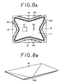
- FIG. 8 A is a diagram illustrating a configuration having electromagnetic wave absorber attached to the inner surfaces of the walls of the anechoic chamber illustrated in Fig. 7 C.
- the walls 12 to 16 are inclined in the same manner as those in the embodiment illustrated in Fig. 3 and Fig. 4 and, at the same time, electromagnetic wave absorbers 40 are attached to the inner surfaces of the wall 12 to 15 as described above.
- the primary reflected waves are prevented from returning to the receiving antenna 22 and the reflected waves are attenuated by the wave-absorbing members 40.
- Fig. 8 B illustrates a configuration having the ceiling wall 16 formed in the general shape of a tetrahedral pyramid so that the distance vertically separating the ceiling wall 16 and the floor wall 11 is smallest in the central part 16a of the ceiling wall and increases in the direction of the four corners of the pyramid.
- a electromagnetic wave absorber 40 is attached to the inner surface of the ceiling wall 16.
- the walls may be selected in either of the two directions in which two opposed pairs of walls are arranged.
- Fig. 9 A to Fig. 9 C are diagrams illustrating a typical anechoic chamber as yet another embodiment of the present invention.
- the component members which have equivalents in the embodiments mentioned above are denoted by the same referential numerals.
- the floor wall 11 is disposed horizontally and the walls 12 to 15 are invariably disposed vertically and the ceiling wall 16 is inclined upwardly in the direction of the central part 16b.
- electromagnetic wave absorbing walls which are formed of a multiplicity of electromagnetic wave absorbers 40 are inclined within the horizontal plane as illustrated in Fig. 9 A and the individual electromagnetic wave absorbers are inclined outwardly in the upward direction as illustrated in Fig. 9 B and Fig. 9 C.
- the electroconductive screens 6 are disposed inside the inner surfaces of the electromagnetic wave absorbing walls as separated by a stated distance therefrom.
- the electroconductive screens 6 are disposed parallel to the electromagnetic wave absorbing walls 41 and are inclined outwardly in the upward direction as illustrated in Fig. 9 B and Fig. 9 C.
- No electroconductive screen 6 is disposed in the portion corresponding to the entrance 42 formed in the lefthand wall 14 as illustrated in Fig. 9 A.
- the reference numeral 21a denotes a turntable which rotatably support the transmission source 21 in place.
- Fig. 10 is a diagram illustrating the disposition of electroconductive screens in a typical anechoic chamber as still another embodiment of this invention. In the diagram, all of the walls described above are omitted. The electroconductive screens are disposed at stated angles without reference to the angles of the walls.
- two electroconductive screens 61, 62 are disposed as inclined in mutually opposite directions relative to the horizontal line, with the part of the center line interconnecting the receiving antenna 22 and the transmitting antenna 21 as the boundary.
- electroconductive screens 63, 64 are disposed as separated respectively by stated distances therefrom and inclined relative to the horizontal line by an angle different from that of the screens 61, 62 mentioned above.
- These screens 61 to 64 are adjoined to the posterior wall 13 mentioned above across an space 80 for seizing waves.
- electroconductive screens 65, 66 are disposed in a stated positional relation with the distance separating the antennas.
- two electroconductive screens 67, 68 are disposed as inclined in the mutually opposite directions relative to the horizontal line.
- the screens 61 to 68 similarly to those in the embodiment mentioned above, are invariably inclined outwardly in the upward direction.
- the screen 61 is inclined outwardly by an angle of 14°
- the screen 61 by an angle of 13°
- the screen 63 and the screen 64 each by an angle of 18°
- screen 65 by an angle of 34°
- the screen 66 by an angle of 31°
- the screen 67 and the screen 68 each by an angle of 28°.
- Fig. 11 illustrates a typical disposition of electroconductive screens as a further embodiment of this invention.
- another electroconductive screen 69 is disposed in a corner portion in addition to the screens 61 to 68 illustrated in Fig. 10.
- the position of this electroconductive screen 69 corresponds to the corner portion where the righthand wall 15 and the anterior wall 12 are joined to each other.
- Fig. 12 illustrates a typical disposition of electroconductive screens as another embodiment of this invention.
- a screen 70 overlapping the screens 61 and 63, a screen 71 overlapping the screens 62 and 64, a screen 72 intervening between the screens 63 and 65, and a screen 73 intervening between the screens 64 and 66 are provided in addition to those screens illustrated in Fig. 10.
- two screens 74 and 75 are connected to the screen 65 and two other screens 76 and 77 are connected to the screen 66.
- the entrance for a worker is formed between the screen 75 mentioned above and a screen 78 partially overlapping the screen 67.
- another entrance 43 is formed between the screen 77 mentioned above and a screen partially overlapping the screen 68.
- FIG. 13 Another embodiment of this invention illustrated in Fig. 13 has substantially the same basic configuration as that of Fig. 12, excepting the screen 79 and the screen 75 are disposed differently.
- the electroconductive screens can be set at arbitrarily selected positions.
Landscapes
- Physics & Mathematics (AREA)
- Electromagnetism (AREA)
- General Physics & Mathematics (AREA)
- Engineering & Computer Science (AREA)
- Microelectronics & Electronic Packaging (AREA)
- Shielding Devices Or Components To Electric Or Magnetic Fields (AREA)
- Building Environments (AREA)
Applications Claiming Priority (2)
| Application Number | Priority Date | Filing Date | Title |
|---|---|---|---|
| JP193061/88 | 1988-08-02 | ||
| JP63193061A JPH0242799A (ja) | 1988-08-02 | 1988-08-02 | 電波無響室 |
Publications (2)
| Publication Number | Publication Date |
|---|---|
| EP0353731A2 true EP0353731A2 (de) | 1990-02-07 |
| EP0353731A3 EP0353731A3 (de) | 1991-01-30 |
Family
ID=16301546
Family Applications (1)
| Application Number | Title | Priority Date | Filing Date |
|---|---|---|---|
| EP19890114262 Withdrawn EP0353731A3 (de) | 1988-08-02 | 1989-08-02 | Anechoischer Raum |
Country Status (3)
| Country | Link |
|---|---|
| EP (1) | EP0353731A3 (de) |
| JP (1) | JPH0242799A (de) |
| KR (1) | KR900004233A (de) |
Cited By (2)
| Publication number | Priority date | Publication date | Assignee | Title |
|---|---|---|---|---|
| KR20190101282A (ko) * | 2019-01-04 | 2019-08-30 | 신건일 | 전자파장해 시험용 전자파반무반향챔버 |
| CN111123370A (zh) * | 2020-01-14 | 2020-05-08 | 中国地质科学院地球物理地球化学勘查研究所 | 电磁波实验装置 |
Family Cites Families (2)
| Publication number | Priority date | Publication date | Assignee | Title |
|---|---|---|---|---|
| GB538623A (en) * | 1940-02-06 | 1941-08-11 | Standard Telephones Cables Ltd | Improvements in or relating to ultra high frequency electron discharge devices using resonators |
| US3273150A (en) * | 1964-03-26 | 1966-09-13 | Goodrich Co B F | Anechoic chamber |
-
1988
- 1988-08-02 JP JP63193061A patent/JPH0242799A/ja active Pending
-
1989
- 1989-08-01 KR KR1019890010999A patent/KR900004233A/ko not_active Ceased
- 1989-08-02 EP EP19890114262 patent/EP0353731A3/de not_active Withdrawn
Cited By (2)
| Publication number | Priority date | Publication date | Assignee | Title |
|---|---|---|---|---|
| KR20190101282A (ko) * | 2019-01-04 | 2019-08-30 | 신건일 | 전자파장해 시험용 전자파반무반향챔버 |
| CN111123370A (zh) * | 2020-01-14 | 2020-05-08 | 中国地质科学院地球物理地球化学勘查研究所 | 电磁波实验装置 |
Also Published As
| Publication number | Publication date |
|---|---|
| KR900004233A (ko) | 1990-03-27 |
| EP0353731A3 (de) | 1991-01-30 |
| JPH0242799A (ja) | 1990-02-13 |
Similar Documents
| Publication | Publication Date | Title |
|---|---|---|
| JP2510880B2 (ja) | 多層型電波吸収体及び該電波吸収体からなる電波暗室 | |
| EP0340012B1 (de) | Reflexarme Kammer für Funkwellen | |
| US5134405A (en) | Electromagnetically anechoic chamber and shield structures therefor | |
| CN116840926B (zh) | 一种非线性节点检测模组、安检装置和安检门 | |
| US20040206527A1 (en) | Frequency-selective shield structure and electric device having the structure | |
| CN106597129B (zh) | 一种微波暗室 | |
| KR101744131B1 (ko) | 가상공간에서의 전자파 무반향실 설계 및 평가방법 | |
| EP0370421A1 (de) | Absorber für elektromagnetische Wellen | |
| CN210626648U (zh) | 一种目标模拟设备 | |
| JPH01114099A (ja) | 電波無響室 | |
| US3365667A (en) | Shielded chamber for measuring electromagnetic or acoustic waves | |
| CN210572721U (zh) | 一种雷达测试暗室 | |
| JPH0242799A (ja) | 電波無響室 | |
| CN206411196U (zh) | 一种微波暗室 | |
| JPH0785517B2 (ja) | 電波暗室 | |
| KR20190101282A (ko) | 전자파장해 시험용 전자파반무반향챔버 | |
| JPH0253337A (ja) | 電波暗室 | |
| HK1046990A1 (en) | Microwave absorber wall | |
| CN111416208A (zh) | 低副瓣天线和其探测方法 | |
| JPH02303095A (ja) | 電波無響室 | |
| JP3475362B2 (ja) | 完全反射型と無反射型兼用のemcテストサイト | |
| CN220324009U (zh) | 片式接收器和遥控接收设备 | |
| KR20110114245A (ko) | 반사벽을 구비한 전파무향실 | |
| JPH04140671A (ja) | 放射イミュニティ評価試験場 | |
| JPH01158797A (ja) | 移動型電波吸収装置 |
Legal Events
| Date | Code | Title | Description |
|---|---|---|---|
| PUAI | Public reference made under article 153(3) epc to a published international application that has entered the european phase |
Free format text: ORIGINAL CODE: 0009012 |
|
| AK | Designated contracting states |
Kind code of ref document: A2 Designated state(s): DE FR GB NL |
|
| PUAL | Search report despatched |
Free format text: ORIGINAL CODE: 0009013 |
|
| AK | Designated contracting states |
Kind code of ref document: A3 Designated state(s): DE FR GB NL |
|
| 17P | Request for examination filed |
Effective date: 19910726 |
|
| 17Q | First examination report despatched |
Effective date: 19920325 |
|
| STAA | Information on the status of an ep patent application or granted ep patent |
Free format text: STATUS: THE APPLICATION IS DEEMED TO BE WITHDRAWN |
|
| 18D | Application deemed to be withdrawn |
Effective date: 19920806 |