EP0353980A2 - Méthode de montage - Google Patents
Méthode de montage Download PDFInfo
- Publication number
- EP0353980A2 EP0353980A2 EP89307779A EP89307779A EP0353980A2 EP 0353980 A2 EP0353980 A2 EP 0353980A2 EP 89307779 A EP89307779 A EP 89307779A EP 89307779 A EP89307779 A EP 89307779A EP 0353980 A2 EP0353980 A2 EP 0353980A2
- Authority
- EP
- European Patent Office
- Prior art keywords
- container
- mounting
- instrument
- frame
- vacuum
- Prior art date
- Legal status (The legal status is an assumption and is not a legal conclusion. Google has not performed a legal analysis and makes no representation as to the accuracy of the status listed.)
- Granted
Links
- 238000000034 method Methods 0.000 title claims abstract description 25
- 238000006073 displacement reaction Methods 0.000 claims description 6
- 230000005469 synchrotron radiation Effects 0.000 abstract description 3
- 230000007246 mechanism Effects 0.000 description 9
- 230000009467 reduction Effects 0.000 description 6
- 238000004519 manufacturing process Methods 0.000 description 4
- 238000005259 measurement Methods 0.000 description 3
- 230000003287 optical effect Effects 0.000 description 3
- 230000008859 change Effects 0.000 description 2
- 230000006866 deterioration Effects 0.000 description 2
- 239000000463 material Substances 0.000 description 2
- 239000004065 semiconductor Substances 0.000 description 2
- 238000005452 bending Methods 0.000 description 1
- 238000006243 chemical reaction Methods 0.000 description 1
- 239000000470 constituent Substances 0.000 description 1
- 230000008602 contraction Effects 0.000 description 1
- 230000008878 coupling Effects 0.000 description 1
- 238000010168 coupling process Methods 0.000 description 1
- 238000005859 coupling reaction Methods 0.000 description 1
- 230000003247 decreasing effect Effects 0.000 description 1
- 238000001514 detection method Methods 0.000 description 1
- 230000004048 modification Effects 0.000 description 1
- 238000012986 modification Methods 0.000 description 1
- 230000003014 reinforcing effect Effects 0.000 description 1
- XLYOFNOQVPJJNP-UHFFFAOYSA-N water Substances O XLYOFNOQVPJJNP-UHFFFAOYSA-N 0.000 description 1
Images



Classifications
-
- G—PHYSICS
- G03—PHOTOGRAPHY; CINEMATOGRAPHY; ANALOGOUS TECHNIQUES USING WAVES OTHER THAN OPTICAL WAVES; ELECTROGRAPHY; HOLOGRAPHY
- G03F—PHOTOMECHANICAL PRODUCTION OF TEXTURED OR PATTERNED SURFACES, e.g. FOR PRINTING, FOR PROCESSING OF SEMICONDUCTOR DEVICES; MATERIALS THEREFOR; ORIGINALS THEREFOR; APPARATUS SPECIALLY ADAPTED THEREFOR
- G03F7/00—Photomechanical, e.g. photolithographic, production of textured or patterned surfaces, e.g. printing surfaces; Materials therefor, e.g. comprising photoresists; Apparatus specially adapted therefor
- G03F7/70—Microphotolithographic exposure; Apparatus therefor
- G03F7/70691—Handling of masks or workpieces
- G03F7/707—Chucks, e.g. chucking or un-chucking operations or structural details
-
- G—PHYSICS
- G03—PHOTOGRAPHY; CINEMATOGRAPHY; ANALOGOUS TECHNIQUES USING WAVES OTHER THAN OPTICAL WAVES; ELECTROGRAPHY; HOLOGRAPHY
- G03F—PHOTOMECHANICAL PRODUCTION OF TEXTURED OR PATTERNED SURFACES, e.g. FOR PRINTING, FOR PROCESSING OF SEMICONDUCTOR DEVICES; MATERIALS THEREFOR; ORIGINALS THEREFOR; APPARATUS SPECIALLY ADAPTED THEREFOR
- G03F7/00—Photomechanical, e.g. photolithographic, production of textured or patterned surfaces, e.g. printing surfaces; Materials therefor, e.g. comprising photoresists; Apparatus specially adapted therefor
- G03F7/70—Microphotolithographic exposure; Apparatus therefor
- G03F7/708—Construction of apparatus, e.g. environment aspects, hygiene aspects or materials
- G03F7/70808—Construction details, e.g. housing, load-lock, seals or windows for passing light in or out of apparatus
- G03F7/70841—Constructional issues related to vacuum environment, e.g. load-lock chamber
-
- G—PHYSICS
- G03—PHOTOGRAPHY; CINEMATOGRAPHY; ANALOGOUS TECHNIQUES USING WAVES OTHER THAN OPTICAL WAVES; ELECTROGRAPHY; HOLOGRAPHY
- G03F—PHOTOMECHANICAL PRODUCTION OF TEXTURED OR PATTERNED SURFACES, e.g. FOR PRINTING, FOR PROCESSING OF SEMICONDUCTOR DEVICES; MATERIALS THEREFOR; ORIGINALS THEREFOR; APPARATUS SPECIALLY ADAPTED THEREFOR
- G03F7/00—Photomechanical, e.g. photolithographic, production of textured or patterned surfaces, e.g. printing surfaces; Materials therefor, e.g. comprising photoresists; Apparatus specially adapted therefor
- G03F7/70—Microphotolithographic exposure; Apparatus therefor
- G03F7/708—Construction of apparatus, e.g. environment aspects, hygiene aspects or materials
- G03F7/70858—Environment aspects, e.g. pressure of beam-path gas, temperature
-
- G—PHYSICS
- G03—PHOTOGRAPHY; CINEMATOGRAPHY; ANALOGOUS TECHNIQUES USING WAVES OTHER THAN OPTICAL WAVES; ELECTROGRAPHY; HOLOGRAPHY
- G03F—PHOTOMECHANICAL PRODUCTION OF TEXTURED OR PATTERNED SURFACES, e.g. FOR PRINTING, FOR PROCESSING OF SEMICONDUCTOR DEVICES; MATERIALS THEREFOR; ORIGINALS THEREFOR; APPARATUS SPECIALLY ADAPTED THEREFOR
- G03F7/00—Photomechanical, e.g. photolithographic, production of textured or patterned surfaces, e.g. printing surfaces; Materials therefor, e.g. comprising photoresists; Apparatus specially adapted therefor
- G03F7/70—Microphotolithographic exposure; Apparatus therefor
- G03F7/708—Construction of apparatus, e.g. environment aspects, hygiene aspects or materials
- G03F7/70858—Environment aspects, e.g. pressure of beam-path gas, temperature
- G03F7/70866—Environment aspects, e.g. pressure of beam-path gas, temperature of mask or workpiece
-
- G—PHYSICS
- G03—PHOTOGRAPHY; CINEMATOGRAPHY; ANALOGOUS TECHNIQUES USING WAVES OTHER THAN OPTICAL WAVES; ELECTROGRAPHY; HOLOGRAPHY
- G03F—PHOTOMECHANICAL PRODUCTION OF TEXTURED OR PATTERNED SURFACES, e.g. FOR PRINTING, FOR PROCESSING OF SEMICONDUCTOR DEVICES; MATERIALS THEREFOR; ORIGINALS THEREFOR; APPARATUS SPECIALLY ADAPTED THEREFOR
- G03F7/00—Photomechanical, e.g. photolithographic, production of textured or patterned surfaces, e.g. printing surfaces; Materials therefor, e.g. comprising photoresists; Apparatus specially adapted therefor
- G03F7/70—Microphotolithographic exposure; Apparatus therefor
- G03F7/708—Construction of apparatus, e.g. environment aspects, hygiene aspects or materials
- G03F7/70858—Environment aspects, e.g. pressure of beam-path gas, temperature
- G03F7/70883—Environment aspects, e.g. pressure of beam-path gas, temperature of optical system
-
- G—PHYSICS
- G12—INSTRUMENT DETAILS
- G12B—CONSTRUCTIONAL DETAILS OF INSTRUMENTS, OR COMPARABLE DETAILS OF OTHER APPARATUS, NOT OTHERWISE PROVIDED FOR
- G12B5/00—Adjusting position or attitude, e.g. level, of instruments or other apparatus, or of parts thereof; Compensating for the effects of tilting or acceleration, e.g. for optical apparatus
Definitions
- the present invention relates to a mounting method of mounting an instrument to a structural member, more particularly to a method for mounting a precision instrument in a vacuum container which is maintained under a reduced pressure in use.
- the method is applicable to a so-called SOR-X rays exposure apparatus wherein a mask and a semiconductor wafer are disposed in a reduced pressure chamber, and exposure energy such as X-rays contained in synchrotron radiation, for example, is projected to the water through the mask, thus printing the pattern of the mask to the wafer. More particularly, it relates to a method in which precision instruments for holding the mask and/or the wafer are suitably mounted to the inside of the vacuum container using the present invention.
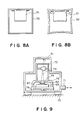
- FIG. 8A shows a conventional mounting of a precision instrument to an inside of a vacuum container.
- Figure 8A shows the container when the external pressure is equal to the internal pressure.
- a precision instrument 51 is directly mounted to the vacuum container 52 using screws or the like at plural positions. The mounting operation is performed while the internal pressure of the vacuum container 2 is the normal atmospheric pressure or the pressure close thereto, after the moving operation, the pressure is reduced to the desired vacuum level.
- Figure 9 shows a conventional X-ray exposure apparatus comprising a vacuum chamber 61, an exhausting port 71, a known rotor type X-ray source 21, an X-ray source supporting frame 72.
- the X-rays are designated by a reference 73.
- a mask 74 having a fine pattern is supported by a mask supporting frame 75.
- a wafer 62 is carried on a wafer carrying table 63 which is supported on a main frame 67.
- the vacuum chamber 61 and the main frame 67 are coupled by a leg 76.
- An anti-vibration unit 70 is provided to protect the entire apparatus from vibration.
- FIG. 8A is a sectional view illustrating the production of the external force to the precision instrument 51 when the pressure is reduced. The external force is shown by the arrows.
- the constituent parts of the precision instrument 51 are changed in their electrical, mechanical and/or optical properties, even to such an extent that the precision instrument 51 would be damaged. Even if the external force is small, the performance of the precision instrument 51 would be deteriorated when the high accuracy is required in the positional relationship between the internal precision instrument 51 and an external instrument.
- the conventional measurements are to increase the thickness of the vacuum container 51 and to add ribs to the container 51, which however result in increase of the weight of the vacuum container leading to cost increase.
- the adjustment of the various instrument and mechanism in the vacuum chamber 61 are executed when the vacuum chamber 61 is communicatd with atmospheric pressure.
- the pressure of the vacuum chamber is reduced through the exhausting port 71 to provide the desired vacuum level in the chamber 61. Therefore, when the pressure is reduced, large force is produced in the wall of the chamber 61 due to the difference between the internal and external pressures, similarly to the apparatus of Figure 8A. This deforms the wall of the container.
- the container wall is influenced by the variation of the ambient pressure, and the amount of deformation changes correspondingly.
- the main frame 67 is a reference base of the exposure apparatus, and on the main frame 67 there are mounted a measurement system (not shown) for positioning the wafer carrying table 63 and a mask supporting frame 75, and therefore, the main frame 67 deformation deteriorates the exposure performance of the apparatus.
- the thickness of the container wall is increased to suppress the deformation, or the rigidity of the main frame 67 is increased, so that the deformation of the main frame 7 is reduced.
- the size, weight and manufacturing cost of the apparatus are increased.
- a mechanism or member is provided at the mounting portion to absorb the external force to the instrument due to deformation of the vacuum chamber such as contraction, expansion or bending.
- the mounting to the vacuum container can be made using a hinge mechanism or a parallel hinge mechanism.
- FIG. 1 an apparatus using the mounting method according to an embodiment of the present invention is shown, wherein the left-right direction, a vertical direction and a front-rear direction are indicated by x, y and z in an x-y-z coordinate system. These directions apply to the subsequent drawings.
- a precision instrument 1 in the form of a unit is inside a vacuum container, the internal pressure thereof is maintained at a desired reduced pressure level when it is in use.
- Supporting members 3 and 4 are provided to hang the precision instrument 1 in the vacuum container 2.
- the mounting members 3 and 4 are spaced apart by a predetermined distance in the direction x.
- the mounting member 3 has a rod 3a having a reduced diameter portion 3b adjacent a longitudinal central portion thereof. This is effective to confine a linear displacement of the precision instrument 1 relative to the wall of the vacuum chamber 2 in all of the directions x, y and z, while permitting rotational movement of the precision instrument 1 in the vacuum container 2 about the x-, y- and z-axes, thus providing a hinge mechanism.
- the mounting member 3 is fixed both to the precision instrument 1 and the vacuum container 2.
- the mounting member 4, as shown in Figure 2B, is in the form of parallel leaf springs 4a and 4b extending in the direction x. This is manufactured by hollowing a mass of a material.
- the mounting member 4 is effective to permit a linear movement in the detection x relative to the vacuum container 2, while confining movements in the directions y and z, thus providing a parallel hinge mechanism.
- the mounting member 4 is mounted between the precision instrument 1 and the vacuum container 2 so as not to confine the rotation of the precision instrument 1 relative to the vacuum container 2 about the axes x, y and z.
- the fine instrument 1 has been mounted to the vacuum container 2, and the inside of the vacuum container 2 communicates with the external, so that the internal pressure of the container is equal to the external pressure (atmospheric pressure) or it is maintained a little lower than that.
- the internal pressure of the vacuum container 2 is reduced by an unshown vacuum pump to a desired reduced pressure level.
- the wall of the vacuum container 2 is contracted and deformed due to the difference between the internal pressure and the external pressure. More particularly, the cubic vacuum container 2, in this embodiment, is deformed such that the central portion of the respective walls displace toward inside.
- the mounting members 3 and 4 having the structure described above absorb the deformation of the container 2, and therefore, the precision instrument 1 is imparted by the force required only for deforming the mounting members 3 and 4 as the reaction force.
- the force can be determined by the shapes and materials of the mounting members 3 and 4. By selecting these properly, the magnitude of the external force can be reduced to a sufficient extent. By doing so, even if the vacuum container 2 deforms from the state of Figure 1A to the state of Figure 1B, the precision instrument 1 can be correctly maintained at the predetermined position in the x-y-z coordinates, according to this embodiment.
- the precision instrument 1 is mounted to the vacuum container 2 wall using two mounting members 3 and 4 to hang it, but another mounting method is usable correspondingly to the shape of the vacuum container 2 and the function of the precision instrument 1.
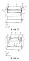
- FIG. 3 there is shown another embodiment wherein the positions of the mounting members 3 and 4 are so selected that the deformation due to the pressure reduction is small, more particularly in the neighborhood 2a and 2b of the corners of the cubic vacuum container 2.
- reinforcing plates 5a and 5b are mounted at the corners 2a and 2b to further strengthen the rigidity of the position where the mounting members 3 and 4 are provided.
- This mounting method is particularly advantageous when a highly precise relative positional relation is desired between the precision instrument 1 and another instrument disposed outside the vacuum container 2.
- FIG. 4 there is shown an embodiment wherein the confinement is imparted to the rotational displacement of the precision instrument 1 about the axis x relative to the vacuum container 2.
- the number of mounting positions is two.
- an additional mounting member 6 is used at the bottom of the precision instrument 1 to confine only the z direction displacement of the precision instrument 1 relative to the vacuum container 2. By this, a swinging movement of the precision instrument 1 about the x axis can be suppressed.
- FIGs 5A and 5B illustrate the details of the mounting member 6.
- the mounting member 6 includes a known spherical seat mechanism 7.
- a movable member 7b is rotatable relative to the housing 7a about the x-axis, y-axis and z-axis as shown in Figure 5A, and simultaneously, the movable member 7b is movable in the directions x and y, while it is confined in the direction z, as shown in Figure 5B.
- An L-shaped rod 8 is fixed to the precision instrument 1 at its end, and is also fixed to the movable member 7b at its other end.
- the housing 7a of the spherical seat mechanism 7 is fixed to the side wall of the vacuum container 2 adjacent a corner 2c.
- the end of the rod 8 is connected to the precision instrument 1 at a position which is substantially the center of the bottom surface of the precision instrument 1 in the direction x.
- a SOR-X ray exposure apparatus utilizing the mounting method of the present invention will be described.
- a mask and a wafer are disposed in a desired reduced pressure ambience, and the exposure energy such as the x-rays contained in a synchrotron radiation is applied to the wafer through the mask to print the pattern of the mask on the wafer.
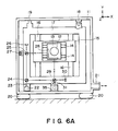
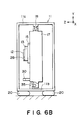
- FIGS. 6A and 6B are front and side views of the apparatus.
- a vacuum container 11 is effective to keep the reduced pressure in the exposure ambience around an unshown mask and a wafer 12.
- An X-stage 13 moves the wafer 12 in the direction x when the shot areas of the wafer 12 are sequentially exposed to the pattern of the mask in a step-and-repeat manner.
- the x-stage 13 is guided by an x-axis guiding bar.
- a y-stage 15 moves the wafer 12 in the direction y during the step-and-repeat exposure, similarly to the x-stage 13.
- the y-stage 15 is guided by a y-axis guiding bar.
- the x-axis guiding bar 14 is secured fixed to the y- stage 15.
- a main frame 17 supports the y-stage 15 through the y-axis guiding bar 16.
- a mounting member 18 having a spherical seat and a mounting member 19 serve to hang the main frame 17 in the vacuum container 11.
- the function of the mounting members are similar to the mounting members 3 and 4 described in conjunction with Figure 1.
- a mounting member 35 having a glancing spherical seat having the same functions as the mounting member 6 shown in Figures 4 and 5A and 5B.
- the apparatus further comprises an anti-vibration unit 20 for the vacuum container 11, a vacuum exhausting port connected to an unshown vacuum pump, a laser source for a laser interferometer for determining the positions of the x-stage 13 and the y-stage 15, a laser optical path 23, half mirrors 24, 25 and 29, a reference mirror 26 for determining the position of the x-stage 13, a detector 27 for the interferometer for determining the position of the x-stage 13, a square mirror 28 movable together with the x-stage 13, a reference mirror 30 for determining the position of the y-stage 15, and a detector for the interferometer for determining the position of the y-stage.
- the port 21 is formed in the vacuum container 11.
- the above elements for determining the position of the x-stage 13 and the y-stage 15 are fixed on the main frame 17.
- This apparatus is assembled in the following manner.
- the y-axis guiding bar 16 is mounted to assure the movement accuracy of the y-stage 15 relative to a reference provided in the main frame 17.
- the x guiding bar 14 is mounted to assure the perpendicularity of the movement of the x-stage 13 relative to the direction of movement of the y-stage 15.
- the position measurement system for the x-stage 13 and the y-stage 15 is all mounted on the main frame 17, and the optical axes are adjusted correctly.
- the above mounting and adjusting operations are performed in the normal atmospheric pressure.
- the supporting member 18 having the spherical seat confines it only in the y direction
- the supporting member 35 having the glancing spherical seat confines it in only z direction.
- the supporting member 19 confines the main frame 17 in all directions to assure the position of the main frame 17 relative to the wall of the chamber.
- the spherical seat is used for absorbing the deformation, but it may be replaced with a leaf spring structure or a sliding mechanism.
- FIGs 7A and 7B are front and side views of the apparatus.
- An L-rod 39 has an end securedly fixed to the top surface of the vacuum container 11 and the other end connected to the bottom surface of the main frame 17 through a supporting member 41 having a spherical sheet.
- the mounting member 41 has the function, the same as that of the supporting member 35 of Figure 6 to confine the displacement of the main frame 17 in the z direction.
- the vacuum container suspended from the anti-vibration base 38 by a mounting member 45 and a mounting member 37 having a spherical seat.
- the mounting member 45 has a confining function in all directions, but the mounting member 17 having the spherical seat confines the displacement only in the y direction of the vacuum chamber 11 relative to the anti-vibration base.
- the mounting points of the mounting members 19 and 45 are aligned in the direction x.
- the supporting points of the mounting members 18 and 37 are along a line extended in the direction y.
- the end of the L-shaped rod having the other end fixed to the anti-vibration plate 38 is connected to the bottom surface of the vacuum chamber 11 through the mounting member 42 having a spherical seat.
- a mounting member 42 confines movement of the vacuum container 11 relative to the anti-vibration base 38 only in the direction z.
- the supporting points of the mounting members 41 and 42 are on a line extending in the direction y.
- the other structures are the same as of Figure 6 apparatus, and the description thereof will be omitted for simplicity. According to this embodiment, the deformation of the anti-vibration base 38 by its own weight is not transmitted to the main frame 17.
- the mounting member for mounting the precision instrument to the vacuum container is deformable or rotatable, and therefore, the external force applied to the precision instrument due to the deformation of the vacuum container resulting from the reduction of the internal pressure can be significantly reduced. This is effective to prevent performance change or damage of the precision instrument.
- the influence of the deformation of the vacuum container is not significantly transmitted to the interval precision instrument, and therefore, the thickness of the vacuum container reduced, so that the weight of the apparatus can be reduced. If the present invention is applied to the precision instrument such as a fine stage or the like used in a semiconductor manufacturing apparatus or the like, the advantageous is very significant in the enhancement of the performance of the precision instrument, reduction of the weight of the entire apparatus and reduction of the size of the apparatus.
Landscapes
- Health & Medical Sciences (AREA)
- Physics & Mathematics (AREA)
- General Physics & Mathematics (AREA)
- Engineering & Computer Science (AREA)
- Environmental & Geological Engineering (AREA)
- Epidemiology (AREA)
- Public Health (AREA)
- Life Sciences & Earth Sciences (AREA)
- Atmospheric Sciences (AREA)
- Toxicology (AREA)
- Exposure And Positioning Against Photoresist Photosensitive Materials (AREA)
Applications Claiming Priority (4)
| Application Number | Priority Date | Filing Date | Title |
|---|---|---|---|
| JP63192193A JP2660553B2 (ja) | 1988-08-02 | 1988-08-02 | 機器取付方法 |
| JP192193/88 | 1988-08-02 | ||
| JP63246314A JP2774527B2 (ja) | 1988-09-30 | 1988-09-30 | 減圧装置 |
| JP246314/88 | 1988-09-30 |
Publications (3)
| Publication Number | Publication Date |
|---|---|
| EP0353980A2 true EP0353980A2 (fr) | 1990-02-07 |
| EP0353980A3 EP0353980A3 (en) | 1990-03-28 |
| EP0353980B1 EP0353980B1 (fr) | 1995-05-24 |
Family
ID=26507168
Family Applications (1)
| Application Number | Title | Priority Date | Filing Date |
|---|---|---|---|
| EP89307779A Expired - Lifetime EP0353980B1 (fr) | 1988-08-02 | 1989-07-31 | Méthode de montage |
Country Status (3)
| Country | Link |
|---|---|
| US (1) | US5687947A (fr) |
| EP (1) | EP0353980B1 (fr) |
| DE (1) | DE68922798T2 (fr) |
Families Citing this family (5)
| Publication number | Priority date | Publication date | Assignee | Title |
|---|---|---|---|---|
| JP3200282B2 (ja) * | 1993-07-21 | 2001-08-20 | キヤノン株式会社 | 処理システム及びこれを用いたデバイス製造方法 |
| JP3745167B2 (ja) * | 1998-07-29 | 2006-02-15 | キヤノン株式会社 | ステージ装置、露光装置およびデバイス製造方法ならびにステージ駆動方法 |
| US6754828B1 (en) * | 1999-07-13 | 2004-06-22 | Intel Corporation | Algorithm for non-volatile memory updates |
| US7384228B2 (en) * | 2004-05-24 | 2008-06-10 | Asml Netherlands B.V. | Insertion device, lithographic apparatus with said insertion device and device manufacturing method |
| JP5315100B2 (ja) * | 2009-03-18 | 2013-10-16 | 株式会社ニューフレアテクノロジー | 描画装置 |
Family Cites Families (10)
| Publication number | Priority date | Publication date | Assignee | Title |
|---|---|---|---|---|
| US2565807A (en) * | 1939-12-04 | 1951-08-28 | Barr & Stroud Ltd | Antivibration supporting arrangement for optical instruments of the telescope type |
| US4106740A (en) * | 1977-03-28 | 1978-08-15 | Westinghouse Electric Corp. | Airborne vibration isolated sensor apparatus |
| US4135688A (en) * | 1977-05-26 | 1979-01-23 | Westinghouse Electric Corp. | Anti-tilting resilient support system for aimed airborne pod-enclosed sensor instruments |
| US4185202A (en) * | 1977-12-05 | 1980-01-22 | Bell Telephone Laboratories, Incorporated | X-ray lithography |
| JPS595179B2 (ja) * | 1979-05-18 | 1984-02-03 | 富士通株式会社 | 真空機器の防振構造 |
| EP0027195B1 (fr) * | 1979-10-11 | 1985-08-07 | Eaton-Optimetrix Inc. | Système d'isolation contre les chocs et vibrations |
| JPS58137633A (ja) * | 1982-02-12 | 1983-08-16 | Matsushita Electric Ind Co Ltd | 圧縮機の支持装置 |
| EP0134268B1 (fr) * | 1983-08-09 | 1987-11-19 | Siemens Aktiengesellschaft | Table de positionnement et d'ajustement et procédé de sa fabrication |
| GB2155201B (en) * | 1984-02-24 | 1988-07-13 | Canon Kk | An x-ray exposure apparatus |
| US4803712A (en) * | 1987-01-20 | 1989-02-07 | Hitachi, Ltd. | X-ray exposure system |
-
1989
- 1989-07-31 EP EP89307779A patent/EP0353980B1/fr not_active Expired - Lifetime
- 1989-07-31 DE DE68922798T patent/DE68922798T2/de not_active Expired - Fee Related
-
1995
- 1995-04-17 US US08/422,932 patent/US5687947A/en not_active Expired - Fee Related
Also Published As
| Publication number | Publication date |
|---|---|
| DE68922798T2 (de) | 1995-11-16 |
| DE68922798D1 (de) | 1995-06-29 |
| EP0353980A3 (en) | 1990-03-28 |
| EP0353980B1 (fr) | 1995-05-24 |
| US5687947A (en) | 1997-11-18 |
Similar Documents
| Publication | Publication Date | Title |
|---|---|---|
| KR100554884B1 (ko) | 진공챔버내에서 이동 가능한 지지체와 리소그래피투영장치에서의 그 적용 | |
| KR100588119B1 (ko) | 리소그래피장치 및 디바이스제조방법 | |
| KR100573669B1 (ko) | 리소그래피 장치용 균형화 위치결정시스템 | |
| US8582080B2 (en) | Stage assembly with measurement system initialization, vibration compensation, low transmissibility, and lightweight fine stage | |
| CN102929104B (zh) | 光学成像装置 | |
| US6188150B1 (en) | Light weight high-stiffness stage platen | |
| JP3947501B2 (ja) | リソグラフィ用機器およびデバイスの製造方法 | |
| JP3983471B2 (ja) | リトグラフ投影装置 | |
| KR100592819B1 (ko) | 리소그래피 장치, 디바이스 제조방법, 및 그것에 의해제조된 디바이스 | |
| US6870600B2 (en) | Vibration-attenuation devices and methods using pressurized bellows exhibiting substantially zero lateral stiffness | |
| EP2053461B1 (fr) | Appareil lithographique doté d'un sous-ensemble d'amortissement | |
| US20070223116A1 (en) | Holding and positioning apparatus for an optical element | |
| KR100573665B1 (ko) | 리소그래피장치 및 디바이스 제조방법 | |
| GB2299867A (en) | Exposure apparatus | |
| US6597435B2 (en) | Reticle stage with reaction force cancellation | |
| EP1814427A2 (fr) | Plateau a positionnement vertical fin | |
| EP0353980B1 (fr) | Méthode de montage | |
| JP2011199317A (ja) | ステージ装置及び露光装置並びにデバイス製造方法 | |
| JPH0242382A (ja) | 移動ステージ構造 | |
| JPH0388400A (ja) | 真空装置 | |
| JP2814401B2 (ja) | 縮小投影機構 | |
| JP6508268B2 (ja) | 移動体装置、露光装置、フラットパネルディスプレイの製造方法、及びデバイス製造方法 | |
| GB2333606A (en) | Exposure apparatus for printing a pattern from a mask on a substrate | |
| WO2024199892A1 (fr) | Système et procédé d'adaptation de rigidité de mandrin |
Legal Events
| Date | Code | Title | Description |
|---|---|---|---|
| PUAI | Public reference made under article 153(3) epc to a published international application that has entered the european phase |
Free format text: ORIGINAL CODE: 0009012 |
|
| AK | Designated contracting states |
Kind code of ref document: A2 Designated state(s): DE FR GB NL |
|
| PUAL | Search report despatched |
Free format text: ORIGINAL CODE: 0009013 |
|
| AK | Designated contracting states |
Kind code of ref document: A3 Designated state(s): DE FR GB NL |
|
| 17P | Request for examination filed |
Effective date: 19900814 |
|
| 17Q | First examination report despatched |
Effective date: 19930202 |
|
| GRAA | (expected) grant |
Free format text: ORIGINAL CODE: 0009210 |
|
| AK | Designated contracting states |
Kind code of ref document: B1 Designated state(s): DE FR GB NL |
|
| REF | Corresponds to: |
Ref document number: 68922798 Country of ref document: DE Date of ref document: 19950629 |
|
| ET | Fr: translation filed | ||
| PLBE | No opposition filed within time limit |
Free format text: ORIGINAL CODE: 0009261 |
|
| STAA | Information on the status of an ep patent application or granted ep patent |
Free format text: STATUS: NO OPPOSITION FILED WITHIN TIME LIMIT |
|
| 26N | No opposition filed | ||
| REG | Reference to a national code |
Ref country code: GB Ref legal event code: IF02 |
|
| PGFP | Annual fee paid to national office [announced via postgrant information from national office to epo] |
Ref country code: NL Payment date: 20040716 Year of fee payment: 16 Ref country code: FR Payment date: 20040716 Year of fee payment: 16 |
|
| PGFP | Annual fee paid to national office [announced via postgrant information from national office to epo] |
Ref country code: GB Payment date: 20040719 Year of fee payment: 16 |
|
| PGFP | Annual fee paid to national office [announced via postgrant information from national office to epo] |
Ref country code: DE Payment date: 20040922 Year of fee payment: 16 |
|
| PG25 | Lapsed in a contracting state [announced via postgrant information from national office to epo] |
Ref country code: GB Free format text: LAPSE BECAUSE OF NON-PAYMENT OF DUE FEES Effective date: 20050731 |
|
| PG25 | Lapsed in a contracting state [announced via postgrant information from national office to epo] |
Ref country code: NL Free format text: LAPSE BECAUSE OF NON-PAYMENT OF DUE FEES Effective date: 20060201 Ref country code: DE Free format text: LAPSE BECAUSE OF NON-PAYMENT OF DUE FEES Effective date: 20060201 |
|
| GBPC | Gb: european patent ceased through non-payment of renewal fee |
Effective date: 20050731 |
|
| PG25 | Lapsed in a contracting state [announced via postgrant information from national office to epo] |
Ref country code: FR Free format text: LAPSE BECAUSE OF NON-PAYMENT OF DUE FEES Effective date: 20060331 |
|
| NLV4 | Nl: lapsed or anulled due to non-payment of the annual fee |
Effective date: 20060201 |
|
| REG | Reference to a national code |
Ref country code: FR Ref legal event code: ST Effective date: 20060331 |