EP0353989A2 - Zylinderkopf für Mehrzylinderbrennkraftmaschinen - Google Patents
Zylinderkopf für Mehrzylinderbrennkraftmaschinen Download PDFInfo
- Publication number
- EP0353989A2 EP0353989A2 EP89307802A EP89307802A EP0353989A2 EP 0353989 A2 EP0353989 A2 EP 0353989A2 EP 89307802 A EP89307802 A EP 89307802A EP 89307802 A EP89307802 A EP 89307802A EP 0353989 A2 EP0353989 A2 EP 0353989A2
- Authority
- EP
- European Patent Office
- Prior art keywords
- cylinder
- intake
- cylinder bank
- exhaust
- ports
- Prior art date
- Legal status (The legal status is an assumption and is not a legal conclusion. Google has not performed a legal analysis and makes no representation as to the accuracy of the status listed.)
- Granted
Links
- 238000002485 combustion reaction Methods 0.000 claims abstract description 47
- 230000007246 mechanism Effects 0.000 claims description 6
- 230000006872 improvement Effects 0.000 abstract description 4
- 230000008878 coupling Effects 0.000 description 38
- 238000010168 coupling process Methods 0.000 description 38
- 238000005859 coupling reaction Methods 0.000 description 38
- 238000005461 lubrication Methods 0.000 description 13
- 230000002349 favourable effect Effects 0.000 description 9
- 239000000203 mixture Substances 0.000 description 9
- 230000000694 effects Effects 0.000 description 6
- 230000009471 action Effects 0.000 description 4
- 239000000446 fuel Substances 0.000 description 4
- 230000008901 benefit Effects 0.000 description 3
- 239000007789 gas Substances 0.000 description 2
- 230000002000 scavenging effect Effects 0.000 description 2
- 238000011144 upstream manufacturing Methods 0.000 description 2
- 229910001018 Cast iron Inorganic materials 0.000 description 1
- 239000000567 combustion gas Substances 0.000 description 1
- 238000010586 diagram Methods 0.000 description 1
- 239000006185 dispersion Substances 0.000 description 1
- 238000005516 engineering process Methods 0.000 description 1
- 239000000463 material Substances 0.000 description 1
- 238000000034 method Methods 0.000 description 1
- 230000008569 process Effects 0.000 description 1
- 230000009467 reduction Effects 0.000 description 1
Images


Classifications
-
- F—MECHANICAL ENGINEERING; LIGHTING; HEATING; WEAPONS; BLASTING
- F01—MACHINES OR ENGINES IN GENERAL; ENGINE PLANTS IN GENERAL; STEAM ENGINES
- F01L—CYCLICALLY OPERATING VALVES FOR MACHINES OR ENGINES
- F01L1/00—Valve-gear or valve arrangements, e.g. lift-valve gear
- F01L1/26—Valve-gear or valve arrangements, e.g. lift-valve gear characterised by the provision of two or more valves operated simultaneously by same transmitting-gear; peculiar to machines or engines with more than two lift-valves per cylinder
- F01L1/267—Valve-gear or valve arrangements, e.g. lift-valve gear characterised by the provision of two or more valves operated simultaneously by same transmitting-gear; peculiar to machines or engines with more than two lift-valves per cylinder with means for varying the timing or the lift of the valves
-
- F—MECHANICAL ENGINEERING; LIGHTING; HEATING; WEAPONS; BLASTING
- F01—MACHINES OR ENGINES IN GENERAL; ENGINE PLANTS IN GENERAL; STEAM ENGINES
- F01L—CYCLICALLY OPERATING VALVES FOR MACHINES OR ENGINES
- F01L1/00—Valve-gear or valve arrangements, e.g. lift-valve gear
- F01L1/02—Valve drive
- F01L1/024—Belt drive
-
- F—MECHANICAL ENGINEERING; LIGHTING; HEATING; WEAPONS; BLASTING
- F02—COMBUSTION ENGINES; HOT-GAS OR COMBUSTION-PRODUCT ENGINE PLANTS
- F02F—CYLINDERS, PISTONS OR CASINGS, FOR COMBUSTION ENGINES; ARRANGEMENTS OF SEALINGS IN COMBUSTION ENGINES
- F02F1/00—Cylinders; Cylinder heads
- F02F1/24—Cylinder heads
- F02F1/42—Shape or arrangement of intake or exhaust channels in cylinder heads
- F02F1/4214—Shape or arrangement of intake or exhaust channels in cylinder heads specially adapted for four or more valves per cylinder
-
- F—MECHANICAL ENGINEERING; LIGHTING; HEATING; WEAPONS; BLASTING
- F02—COMBUSTION ENGINES; HOT-GAS OR COMBUSTION-PRODUCT ENGINE PLANTS
- F02B—INTERNAL-COMBUSTION PISTON ENGINES; COMBUSTION ENGINES IN GENERAL
- F02B1/00—Engines characterised by fuel-air mixture compression
- F02B1/02—Engines characterised by fuel-air mixture compression with positive ignition
- F02B1/04—Engines characterised by fuel-air mixture compression with positive ignition with fuel-air mixture admission into cylinder
-
- F—MECHANICAL ENGINEERING; LIGHTING; HEATING; WEAPONS; BLASTING
- F02—COMBUSTION ENGINES; HOT-GAS OR COMBUSTION-PRODUCT ENGINE PLANTS
- F02B—INTERNAL-COMBUSTION PISTON ENGINES; COMBUSTION ENGINES IN GENERAL
- F02B75/00—Other engines
- F02B75/16—Engines characterised by number of cylinders, e.g. single-cylinder engines
- F02B75/18—Multi-cylinder engines
- F02B2075/1804—Number of cylinders
- F02B2075/1816—Number of cylinders four
-
- F—MECHANICAL ENGINEERING; LIGHTING; HEATING; WEAPONS; BLASTING
- F02—COMBUSTION ENGINES; HOT-GAS OR COMBUSTION-PRODUCT ENGINE PLANTS
- F02B—INTERNAL-COMBUSTION PISTON ENGINES; COMBUSTION ENGINES IN GENERAL
- F02B2275/00—Other engines, components or details, not provided for in other groups of this subclass
- F02B2275/18—DOHC [Double overhead camshaft]
-
- F—MECHANICAL ENGINEERING; LIGHTING; HEATING; WEAPONS; BLASTING
- F02—COMBUSTION ENGINES; HOT-GAS OR COMBUSTION-PRODUCT ENGINE PLANTS
- F02F—CYLINDERS, PISTONS OR CASINGS, FOR COMBUSTION ENGINES; ARRANGEMENTS OF SEALINGS IN COMBUSTION ENGINES
- F02F1/00—Cylinders; Cylinder heads
- F02F1/24—Cylinder heads
- F02F2001/244—Arrangement of valve stems in cylinder heads
- F02F2001/247—Arrangement of valve stems in cylinder heads the valve stems being orientated in parallel with the cylinder axis
Definitions
- the present invention relates to a cylinder head structure for plural cylinder engines which allows more compact design of an engine than was possible heretofore, and in particular to such a cylinder head structure which can be advantageously used in combination with an engine using a plurality of intake and/or exhaust valves having different flow rate properties for each cylinder.
- valve control technology known as combination valve timing according to which a swirl is produced in the mixture introduced into the combustion chamber by shifting the opening and closing timing of the plural valves (Japanese patent laid-open publication No. 59-147822).
- the temperature of combustion gas is extremely high and its flow speed may reach the sonic speed. It is therefore desirable to minimize the flow resistance of the exhaust passages to improve exhaust efficiency by taking advantage of the flow speed of exhaust gas.
- the exhaust manifold which merges the exhaust passages leading to the exhaust ports opening out into the cylinder head is generally made of cast iron because of the heat resisting property of the material, and the exhaust manifold is desired to be made as small as possible to make room for mounting accessory equipment and to reduce the overall weight of the engine. A similar consideration applies also to the intake system of the engine.
- the present invention provides a cylinder head structure for a plural cylinder engine, comprising, at least for each of its cylinders located at either longitudinal end of its cylinder bank: a combustion chamber defined by the cylinder and a piston received therein; an intake passage communicated with an intake manifold at its one end and with the combustion chamber at its other end; and an exhaust passage communicated with an exhaust manifold at its one end and with the combustion chamber at its other end; at least one of the intake passage and the exhaust passage being curved toward a longitudinally central part of the cylinder bank as it extends from its other end to its one end, the curved passage being communicated with the combustion chamber at its other end by at least two ports which are controlled by valves and arranged along a longitudinal direction of the cylinder bank, and one of the ports involving a relatively larger flow rate being disposed closer to a longitudinally central part of the cylinder bank than the other port involving a relatively smaller flow rate.
- the mounting surface of the intake and/or exhaust manifold for mounting it on a cylinder head can be reduced in the dimension along the longitudinal direction of the cylinder bank, and the overall size and weight of the engine can be reduced.
- the intake and/or exhaust passage can be made shorter and smoother, the performance of the engine can be also improved.
- an overall improvement in volumetric efficiency can be achieved.
- a favorable swirl effect may be obtained and a favorable mixing of fuel with air can be achieved.
- the curved passage consists of an exhaust passage, and an intake passage is communicated with the combustion chamber by at least two ports which are controlled by intake valves and arranged along a longitudinal direction of the cylinder bank, one of the intake ports involving a relatively smaller flow rate being disposed closer to a longitudinally central part of the cylinder bank than the other intake port involving a relatively larger flow rate.
- a favorable scavenging effect can be obtained in addition to a favorable volumetric efficiency.
- the exhaust and intake valves are controlled by a valve actuating mechanism in such a manner that all the valves are fully opened in a high engine speed range, and one of the intake valves remote from a longitudinally central part of the cylinder bank and one of the exhaust valves close to a longitudinally central part of the cylinder bank are opened to intermediate extents while the other intake valve and the other exhaust valve are opened to small extents in a low engine speed range.
- a favorable swirl effect can be produced in the flow of air/fuel mixture, and a favorable volumetric efficiency can be achieved.
- one of the intake ports involving a relatively larger flow rate may be disposed closer to a longitudinally central part of the cylinder bank than the other intake port involving a relatively smaller flow rate so that a favorable volumetric efficiency may be obtained.
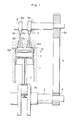
- Figure 1 shows a four-stroke multiple cylinder engine to which the present invention is applied.
- the piston 2 slidably received in each cylinder 1 is coupled with a small end of a connecting rod 4 via a piston pin 3, and a big end of the connecting rod 4 is coupled with a crank pin 5a of a crankshaft 5.
- the rotation of the crankshaft 5 is transmitted to a camshaft 8 at a speed reduction factor of 1/2 via a timing belt 9 passed around a crank pulley 6 fixedly attached to an end of the crankshaft 5 and a cam pulley 8a fixedly attached to an end of the camshaft 8 supported by a cylinder head 7.
- the intake and exhaust valves are substantially identical to one another and are arranged in symmetrical fashion. As the intake valves and the exhaust valves are arranged symmetrically to the central longitudinal line of the cylinder bank, either the intake valves or the exhaust valves are referred to in some of the following description without specifying which of them are referred to.
- the camshaft 8 is provided with a pair of cams 10a and 10b for each cylinder 1, and these cams actuate two valves 12a and 12b via rocker arms 11a and 11b in reciprocating fashion so as to open and close intake ports 14a and 14b or exhaust ports 15a and 15b, as the case may be, opening into a combustion chamber 13 according to the various stroke processes of the internal combustion engine carried out in the combustion chamber 13.
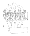
- the cylinder head 7 is provided, for each of its combustion chambers 13, with a pair of intake ports 14a and 14b and a pair of exhaust ports 15a and 15b which are closed and opened by a pair of intake valves and a pair of exhaust valves.
- These ports 14a, 14b, 15a and 15b are communicated with intake openings 16 and exhaust openings 17 which are provided on either side end of the cylinder head 7, via intake passages 18 and exhaust passages 19 provided in the cylinder head 7.
- the intake openings 16 and the exhaust openings 17 are shifted towards a longitudinally central part of the cylinder bank in relation with the positions of the corresponding combustion chambers, and, accordingly, the intake passages 18 and the exhaust passages 19 are slightly curved towards the center as they move away from the corresponding combustion chambers 13.
- Each of the intake passages 18 diverges into two parts which lead to the intake ports 14a and 14b at a point immediately upstream of the intake ports 14a and 14b, and each of the exhaust passages 19 converges from two parts leading to the exhaust ports 15a and 15b into one at a point immediately downstream of the exhaust ports 15a and 15b.
- An intake manifold 20 and an exhaust manifold 21 are securely attached to the corresponding side ends of the cylinder head 7 at which the intake openings 16 and the exhaust openings 17 open up.
- the intake manifold 20 comprises intake tubes 20a which are individually communicated with the corresponding intake openings 16, and an intake chamber 20b with which the intake passages 20a are commonly communicated at their upstream ends.
- the exhaust tubes 21a connected to the two centrally located exhaust openings 19 are joined at a longitudinally central part of the cylinder bank, and the exhaust passages 21b communicated with the longitudinally externally located exhaust openings 19 are also joined at a central part.
- these two merging parts 21c and 21d are aligned along a plane perpendicular to the longitudinal direction of the cylinder bank.
- the intake manifold and the exhaust manifold of an in-line multiple cylinder engine are typically merged in a central part with respect to the longitudinal direction of the cylinder bank, by shifting the intake openings 16 and the exhaust openings 17 towards a central part with respect to the longitudinal direction of the cylinder bank, instead of simply extending intake and exhaust passages laterally from the combustion chambers 13, the dimensions of the intake manifold 20 and the exhaust manifold 21 can be reduced significantly.
- the two valves 12a and 12b are opened and closed according to different valve lift curves as shown in Figure 5; the valve 12b closer to the longitudinally central part of the cylinder bank is driven according to a lift curve CH which opens the valve over a relative large crank angle and by a relatively large valve lift while the external valve 12a is driven according to another lift curve CL which opens the valve over a relative small crank angle and by a relatively small valve lift.
- the intake passages 18 and the exhaust passages 19 are curved toward the longitudinally central part of the cylinder bank as they move away from the combustion chambers 13, the parts of the intake passages 18 and the exhaust passages 19 located closer to the longitudinally central part of the cylinder bank are relatively short and linear as compared with the parts of the intake passages 18 and the exhaust passages 19 located remote from the longitudinally central part of the cylinder bank, and therefore involve relatively small flow resistance.
- the high-flow rate and high-lift intake or exhaust valves 12b in the parts of the flow passages 18 or 19 involving relatively small flow resistance, an improvement in overall volumetric efficiency can be achieved.
- the resulting uneveness in the flow speed of the mixture in the combustion chamber 13 contributes to more favorable dispersion of the mixture and improvement of combustion efficiency.
- a plurality (two in the present case) of intake and exhaust valves are provided for each cylinder and a difference is thereby created in the flow rates of mixture or exhaust gas in these ports 14a, 14b, 15a and 15b, but it is also possible to create such a difference by making those ports 14b′ and/or 15b′ located closer to the longitudinally central part of the cylinder bank larger than those ports 14a′ and/or 15a′ located more remote from the longitudinally central part of the cylinder bank, as shown in Figure 6. Further, it is also possible to combine the effects of the differences in the crank angle range for opening the valves, the lifts of the valves, and the opening areas of the ports.
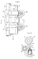
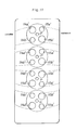
- Figure 7 shows a second embodiment of the present invention which is applied to a V-type six-cylinder engine.
- each cylinder bank of a V-type engine consists of an odd number of cylinders or in case where the engine consists of an in-line engine having an odd number of cylinders such as an in-line three or five cylinder engine
- ports 36a and 37a of relatively small flow rates may be arranged in external parts of the combustion chamber 31a and 31c with respect to the longitudinal line of the cylinder bank while ports 36b and 37b of relatively large flow rates may be arranged in relatively central parts along the longitudinal line of the cylinder bank.
- the engine of the present embodiment also consists of a DOHC type in-line four-cylinder engine in which intake valves and exhaust valves are driven by separate camshafts and two intake valves and two exhaust valves are provided for each cylinder as was the case in the first and the second embodiments.
- These two kinds of valves are driven according to different timing schedule, but as they have basically identical structures, the structure of the valve actuating system is described in the following without specifying the kind of the valves.
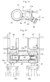
- the rocker shaft 50 fixedly secured to a cylinder head 59 pivotally supports three rocker arms 51, 52 and 53 in individually rotatable manner one next to the other for each cylinder.
- a camshaft 54 is supported above these rocker arms 51, 52 and 53 by way of camshaft bearings provided in the cylinder head 59.
- the camshaft 54 is provided with a first low-speed cam 55 involving a relatively small crank angle range for opening the valve and a relatively small valve lift, a high-speed cam 56 involving a relatively large crank angle range for opening the valve and a relatively large valve lift, and a second low-speed cam 57 involving an intermediate crank angle range for opening the valve and an intermediate valve lift.
- first rocker arm 51 cooperating with the first low-speed cam 55, and the second rocker arm 52, cooperating with the second low-speed cam 57, abut the upper stem ends of a pair of valves 58a and 58b, respectively, which are normally urged in valve closing direction by coil springs (refer to Figure 9).
- the third rocker arm 53 which is located between the first and the second rocker arms 51 and 52 and cooperate with the high-speed cam 56 is normally urged upward by a lifter 60 provided in a part the cylinder head 59 corresponding to the third rocker arm 53 (refer to Figure 10).
- the mutually adjoining first through third rocker arms 51 through 53 are internally provided with a coupling control device 61 (refer to Figure 11).
- This coupling control device 61 comprises lateral guide bores provided in the rocker arms 51, 52 and 53, and coupling pins are slidably received in these guide bores.
- the first rocker arm 51 is provided with a first guide bore 62 which opens out towards the third rocker arm 53 at its one end and is closed at its other end, and a first coupling pin 63 is slidably received in the first guide bore 62.
- the closed bottom end of the first guide bore 62 defining a chamber 64a is communicated with an oil passage 66 provided in the rocker shaft 50 via an oil passage 64 formed in the first rocker arm 51 and an oil supply port 65 provided in the rocker shaft 50.
- the third rocker arm 53 is provided with a second guide bore 67 which is of the same diameter as the first guide bore 62 and is positioned coaxially with the first guide bore 62 when its cam slipper 53a is in contact with a base circle part of the high-speed cam 56, and these guide bores extend in parallel with the rocker shaft 50.
- a second coupling pin 68 is slidably received in the second guide bore 69 so as to abut the first coupling pin 63.
- the second rocker arm 52 is likewise provided with a third guide bore 69 having a closed end, and receiving therein a stopper pin 70 which abuts the other end of the second coupling pin 68 at its one end.
- the stopper pin 70 is cylindrical in shape and partly closed at its one end, and is normally urged toward the third rocker arm 53 under the spring force of a return spring 71 interposed between its inner bottom surface and the bottom surface of the third guide bore 69.
- a pair of oil supply conduits 82 and 83 are arranged above the camshaft 54 for each cylinder bank so as to lubricate the sliding surfaces defined in the camshaft bearing 81 and between the cam slippers 51a, 52a and 53a formed on the upper surfaces of the rocker arms 51, 52 and 53.
- a downstream end of the oil supply passage 66 provided in the rocker shaft 50 is connected to the high-speed lubrication oil supply conduit 82 of the aforementioned oil supply conduits.
- This high-speed lubrication oil supply conduit 82 is provided with oil jet orifices 84 to spew lubrication oil to corresponding parts of the third rocker arms 53.
- the low-speed lubrication oil supply conduit 83 is connected to a lubrication oil passage 86 which is branched off from an oil gallery 85.
- the low-speed lubrication oil supply conduit 85 is provided with oil jet orifices 87 to spew lubrication oil to corresponding parts of the first rocker arms 51 and the second rocker arms 52, as well as to the cam bearings 81 via oil passages 88.
- An oil pressure control valve 89 is provided between the oil passage 66 provided in the rocker shaft 50 and the oil gallery 85, and is controlled by a control signal supplied from a control unit not shown in the drawings. When this oil pressure control valve 89 is closed, no oil pressure is supplied to the oil supply passage 66 and the coupling pins 63 and 68 are urged towards their decoupled states by the return spring 71 so that the rocker arms 51, 52 and 53 may be individually driven by the corresponding cams 55, 56 and 57.
- the lubrication oil supplied from an oil pan 91 to the oil gallery 85 by a pump 90 is supplied to the low-speed lubrication oil supply passage 83 via the lubrication oil passage 86 to lubricate the sliding surfaces between the first and the second low-speed cams 55 and 57 and the cam slippers 51a and 52a of the first and second rocker arms as well as the cam bearings 81.
- the lubrication oil supplied to the oil supply passage 66 not only actuates the coupling control device 61 for each cylinder but also is supplied to the high-speed lubrication oil supply conduit 82 via the downstream end of the oil supply passage 86 to lubricate the sliding surface between the high speed cam 56 and the cam slipper 53a of the third rocker arm 53.
- the first coupling pin 63 slides into the second guide bore 67 and the second coupling pin 68 slides into the third guide bore 69 against the spring force of the return spring 71 so as to couple the three rocker arms 51, 52 and 53 with one another. Since the cam profile of the high-speed cam 56 is larger than those of the first and second low-speed cams 55 and 57, the first and second rocker arms 51 and 52 are also driven by the high-speed cam 56 in the center, and the valves 58a and 58b are both driven according to the crank angle region for opening the valve and the valve lift of the high speed mode as represented by the curve H in Figure 13.
- the rocker arms 51, 52 and 53 can move individually.
- the third rocker arm 53 in the center simply pushes the lifter 60 driven by the high-speed cam 56 and undergoes a lost-motion movement whereas the first rocker arm 51 and the second rocker arm 52 actuate the valves 58a and 58b, respectively, according to different crank angle regions for opening the valves and valve lifts, driven by the first low-speed cam 55 and the second low-speed cam 57, respectively.
- one of the valves 58a is actuated according to the curve L of Figure 13 corresponding to the cam profile of the first low-speed cam 55 so as to have a smallest crank angle range for opening the valve and a smallest valve lift while the other valve 58b is actuated according to the curve M of Figure 13 corresponding to the cam profile of the second low-speed cam 57 so as to have an intermediate crank angle range for opening the valve and an intermediate valve lift.
- the third rocker arm 53 is provided with a relatively large width or a relatively large longitudinal dimension along the longitudinal line of the rocker shaft 50 to reduce the magnitude of its surface pressure per unit area to compensate for its large valve lift, the sliding resistance of the second coupling pin 68 is greater than those of the other coupling pins. Therefore, the first coupling pin 63 may return to the first guide bore 62 slightly before the third coupling pin 68 depending on inertia and friction conditions. Therefore, the decoupling between the third rocker arm 53 and the first rocker arm 51 may occur before the decoupling between the third rocker arm 53 and the second rocker arm 52.
- the possibility of failing to complete a decoupling action during a base circle part of the corresponding cam is higher between the third rocker arm 53 and the second rocker arm 52 than between the third rocker arm 53 and the first rocker arm 51.
- An occurrence of a decoupling action at an intermediate point of a valve lift means that the cam slipper of one of the rocker arms is thrown against the cam surface by a stroke equal to the difference between the valve lifts effected by the two different cam profiles corresponding to the two rocker arms in question, and an impulsive striking noise may be generated as a result.
- the coupling between the third rocker arm 53 corresponding to the high-speed cam 56 for the large valve lift and the second rocker arm 52 corresponding to the second low-speed cam 57 is accomplished by the second coupling pin 68 which can less readily slide than the first coupling pin 63 so that the impact of the rocker arm upon the cam surface would be minimized even when a decoupling action should occur during a valve lift stroke.
- the first rocker arm 51 is provided with a cylindrical bearing portion 73 at a base end of its arm portion 74 for passing the rocker shaft 50 therethrough, and a threaded bore 76 is provided in a free end of the arm portion 74 for engaging a tappet screw therein.
- An intermediate part of the arm portion 74 is provided with a cylindrical portion 75 for defining the first guide bore 62 therein.
- the cam slipper 51a is provided in the arm portion 74 adjacent to the cylindrical portion 75.
- the first guide bore 62 is offset from the center of the cylindrical portion 75 towards the cam slipper 51a so that the thickness t2 of the cylindrical portion 75 adjacent to the cam slipper 51a is substantially smaller than the thickness t1 of the cylindrical portion 75 remote from the cam slipper 51a.
- the second rocker arm 52 is substantially identical to the first rocker arm 51, and its guide bore 69 is likewise offset from the center of its cylindrical portion 77.
- the coupling pins 63, 68 are manufactured so as to have a certain range of tolerance, and a certain play is inevitable between the coupling pins and the corresponding bores. Therefore, when the rocker arms 51,52 and 53 are actuated by the high speed cam 56, the coupling pins 63 and 68 tend to slant with respect to the guide bores 62, and 67 and 69 as illustrated in Figure 15 in exaggerated form. Therefore, relatively large loads are applied to lower parts of the cylindrical portions 75 and 77 of the first and the second rocker arms 51 and 52. However, since these parts are made thicker than the upper parts of the cylindrical portions 75 and 77, a sufficient rigidity and mechanical strength can be ensured. On the other hand, because the upper parts of the cylindrical portions 75 and 77 receive relatively small forces from the coupling pins 63 and 68, and are reinforced by the cam slippers 51a and 52a, reducing their thicknesses would not create any problem
- each cylinder has two intake valves 58Ia and 58Ib and two exhaust valves 58Ea and 58Eb.
- the three rocker arms 51, 52 and 53 are integrally coupled by the coupling pins 63 and 68, and these valves are fully opened by the high speed cam 56.
- the intake valve 58Ia controlling an intake port 114b located closer to the longitudinal center of the cylinder bank is opened over a small crank angle region and its valve lift is small while the other intake valve 58Ib controlling an intake port 114a located more remote from the longitudinal center of the cylinder bank is opened over a relatively large crank angle region and its valve lift is intermediate or relatively large.
- the exhaust valve 58Ea controlling an exhaust port 115a located more remote from the longitudinal center of the cylinder bank is opened over a small crank angle region and its valve lift is small while the other exhaust valve 58Eb controlling an exhaust port 115b located closer to the longitudinal center of the cylinder bank is opened over a relatively large crank angle region and its valve lift is intermediate or relatively large.
- the exhaust valve 58Eb of a relatively large flow rate located closer to the longitudinal central part of the cylinder bank opens earlier than and closes later than the other exhaust valve 58Ea. Furthermore, since the exhaust passage 119 communicated with the exhaust valve 58Eb of a larger flow rate is more linear and involves less resistance than the other, the exhaust flow in the combustion chamber 113 is directed towards the exhaust valve 58Eb located closer to the longitudinally central part of the cylinder bank as indicated by the arrow E as shown in Figure 16.
- the intake valve 58Ib of a relatively large flow rate located further away from the longitudinal central part of the cylinder bank opens earlier than and closes later than the other intake valve 58Ia. Furthermore, since the intake passage 118 communicated with the intake valve 58Ib of a larger flow rate is curved leftward as seen along the direction of the flow of air/fuel mixture, the mixture flows into the combustion chamber 113 along a substantially tangential direction. Therefore, the intake flow in the combustion chamber 113 is directed as indicated by the arrow I as shown in Figure 16. This is directed in parallel with the direction indicated by the arrow E, and a swirl effect is promoted. By thus creating a difference in flow rate in diametric direction, it becomes possible to achieve a high volumetric efficiency of the engine, a favorable mixing of air and fuel, and a high scavenging effect.
- the present invention provides a cylinder head structure for multiple cylinder engines which can substantially reduce the size and weight of its intake and/or exhaust manifold, and which can improve the volumetric efficiency of the engine.
Landscapes
- Engineering & Computer Science (AREA)
- Mechanical Engineering (AREA)
- General Engineering & Computer Science (AREA)
- Chemical & Material Sciences (AREA)
- Combustion & Propulsion (AREA)
- Valve-Gear Or Valve Arrangements (AREA)
- Cylinder Crankcases Of Internal Combustion Engines (AREA)
- Valve Device For Special Equipments (AREA)
Applications Claiming Priority (2)
| Application Number | Priority Date | Filing Date | Title |
|---|---|---|---|
| JP19237788 | 1988-08-01 | ||
| JP192377/88 | 1988-08-01 |
Publications (3)
| Publication Number | Publication Date |
|---|---|
| EP0353989A2 true EP0353989A2 (de) | 1990-02-07 |
| EP0353989A3 EP0353989A3 (de) | 1990-05-23 |
| EP0353989B1 EP0353989B1 (de) | 1996-10-23 |
Family
ID=16290280
Family Applications (1)
| Application Number | Title | Priority Date | Filing Date |
|---|---|---|---|
| EP89307802A Expired - Lifetime EP0353989B1 (de) | 1988-08-01 | 1989-08-01 | Zylinderkopf für Mehrzylinderbrennkraftmaschinen |
Country Status (5)
| Country | Link |
|---|---|
| US (1) | US5007392A (de) |
| EP (1) | EP0353989B1 (de) |
| JP (1) | JPH02140407A (de) |
| CA (1) | CA1326618C (de) |
| DE (1) | DE68927359T2 (de) |
Families Citing this family (25)
| Publication number | Priority date | Publication date | Assignee | Title |
|---|---|---|---|---|
| JPH04292526A (ja) * | 1991-03-20 | 1992-10-16 | Honda Motor Co Ltd | 4サイクル内燃機関 |
| US5445116A (en) * | 1992-12-22 | 1995-08-29 | Unisia Jecs Corporation | Hydraulic variable lift engine valve gear |
| US5429086A (en) | 1994-02-14 | 1995-07-04 | Cummins Engine Company, Inc. | Shared runner intake ports for I.C. engine |
| GB9920666D0 (en) | 1999-09-01 | 1999-11-03 | Zalkin Anthony L | Improved internal combustion engine |
| DE10210747A1 (de) * | 2002-03-12 | 2003-10-02 | Ina Schaeffler Kg | Verfahren zur Herstellung von schaltbaren Ventiltriebsgliedern einer Brennkraftmaschine |
| DE10360098B4 (de) * | 2003-12-20 | 2015-03-12 | Schaeffler Technologies AG & Co. KG | Koppelmechanismus |
| DE102005048561A1 (de) * | 2005-10-11 | 2007-04-12 | Bayerische Motoren Werke Ag | Zylinderkopf für eine Brennkraftmaschine |
| DE102007057310A1 (de) * | 2007-11-28 | 2009-06-04 | Continental Automotive Gmbh | Verbrennungsmotor mit integrierten Abgaskrümmern |
| DE102010030499A1 (de) | 2010-06-24 | 2011-12-29 | Man Diesel & Turbo Se | Zylinderkopf und damit ausgerüstete Brennkraftmaschine |
| US20120006295A1 (en) * | 2010-07-12 | 2012-01-12 | Gm Global Technology Operations, Inc. | Engine assembly including asymmetric exhaust valve configuration |
| US10590813B2 (en) | 2017-03-30 | 2020-03-17 | Quest Engines, LLC | Internal combustion engine |
| US10465629B2 (en) | 2017-03-30 | 2019-11-05 | Quest Engines, LLC | Internal combustion engine having piston with deflector channels and complementary cylinder head |
| US10989138B2 (en) | 2017-03-30 | 2021-04-27 | Quest Engines, LLC | Internal combustion engine |
| US10753308B2 (en) | 2017-03-30 | 2020-08-25 | Quest Engines, LLC | Internal combustion engine |
| US10526953B2 (en) | 2017-03-30 | 2020-01-07 | Quest Engines, LLC | Internal combustion engine |
| US10598285B2 (en) | 2017-03-30 | 2020-03-24 | Quest Engines, LLC | Piston sealing system |
| US10590834B2 (en) | 2017-03-30 | 2020-03-17 | Quest Engines, LLC | Internal combustion engine |
| US11041456B2 (en) | 2017-03-30 | 2021-06-22 | Quest Engines, LLC | Internal combustion engine |
| JP6894981B2 (ja) | 2017-04-28 | 2021-06-30 | クエスト エンジンズ,エルエルシー | 可変容積室デバイス |
| WO2018204684A1 (en) | 2017-05-04 | 2018-11-08 | Quest Engines, LLC | Variable volume chamber for interaction with a fluid |
| US11060636B2 (en) | 2017-09-29 | 2021-07-13 | Quest Engines, LLC | Engines and pumps with motionless one-way valve |
| WO2019147797A2 (en) | 2018-01-26 | 2019-08-01 | Quest Engines, LLC | Audio source waveguide |
| US10753267B2 (en) | 2018-01-26 | 2020-08-25 | Quest Engines, LLC | Method and apparatus for producing stratified streams |
| US11578647B2 (en) | 2020-03-11 | 2023-02-14 | Arctic Cat Inc. | Engine |
| CN116025452A (zh) * | 2022-12-30 | 2023-04-28 | 东风商用车有限公司 | 一种用于发动机的排气道结构、发动机及车辆 |
Family Cites Families (11)
| Publication number | Priority date | Publication date | Assignee | Title |
|---|---|---|---|---|
| GB2134977B (en) * | 1983-01-29 | 1987-08-26 | Bothwell P W | Internal combustion engine and cylinder head therefor |
| US4538547A (en) * | 1984-03-23 | 1985-09-03 | Luis Del Rosario | Fishtank |
| SE464099B (sv) * | 1985-01-29 | 1991-03-04 | Honda Motor Co Ltd | Foerbraenningsmotor innefattande cylinder med ovalt tvaersnitt |
| US4669434A (en) * | 1985-07-24 | 1987-06-02 | Toyota Jidosha Kabushiki Kaisha | Internal combustion engine cylinder head variable swirl siamese type intake port structure, with auxiliary straight passage, pointing at spark plug, leading from mixture intake to downstream end of straight intake port |
| JPS62121811A (ja) * | 1985-07-31 | 1987-06-03 | Honda Motor Co Ltd | 内燃機関の動弁装置 |
| JPH0415937Y2 (de) * | 1985-10-14 | 1992-04-09 | ||
| US4726343A (en) * | 1986-03-20 | 1988-02-23 | Volkswagen Ag | Suction pipe arrangement for multi-cylinder internal combustion engines with fuel injection nozzles |
| FR2601076B1 (fr) * | 1986-07-04 | 1988-10-21 | Peugeot | Culasse de moteur a combustion interne a trois soupapes par cylindre et a forte pression dans les cylindres. |
| JPS6357806A (ja) * | 1986-08-27 | 1988-03-12 | Honda Motor Co Ltd | 内燃機関の動弁装置 |
| US4703729A (en) * | 1986-10-14 | 1987-11-03 | Kubota Ltd. | Intake system with double intake ports for internal combustion engine |
| JPS63167016A (ja) * | 1986-12-27 | 1988-07-11 | Honda Motor Co Ltd | 多気筒内燃機関の動弁装置 |
-
1989
- 1989-06-20 JP JP1157123A patent/JPH02140407A/ja active Pending
- 1989-07-31 CA CA000607029A patent/CA1326618C/en not_active Expired - Fee Related
- 1989-08-01 US US07/388,259 patent/US5007392A/en not_active Expired - Lifetime
- 1989-08-01 DE DE68927359T patent/DE68927359T2/de not_active Expired - Fee Related
- 1989-08-01 EP EP89307802A patent/EP0353989B1/de not_active Expired - Lifetime
Also Published As
| Publication number | Publication date |
|---|---|
| DE68927359D1 (de) | 1996-11-28 |
| JPH02140407A (ja) | 1990-05-30 |
| DE68927359T2 (de) | 1997-02-20 |
| EP0353989A3 (de) | 1990-05-23 |
| CA1326618C (en) | 1994-02-01 |
| US5007392A (en) | 1991-04-16 |
| EP0353989B1 (de) | 1996-10-23 |
Similar Documents
| Publication | Publication Date | Title |
|---|---|---|
| EP0353989B1 (de) | Zylinderkopf für Mehrzylinderbrennkraftmaschinen | |
| US5606942A (en) | Valve operating system for multi-valve engine | |
| US5758612A (en) | Valve actuating structure for multi-valve engine | |
| CN101149003B (zh) | 多气缸内燃机 | |
| US6289861B1 (en) | Control for variable valve timing | |
| US4754729A (en) | Camshaft support assembly for valve operating mechanism in an internal combustion engines | |
| US5031586A (en) | Multi-valve engine | |
| EP0601250A1 (de) | Hubventilsteuerungsvorrichtung für Brennkraftmaschine | |
| EP0607992B1 (de) | Einlassvorrichtung für Brennkraftmaschine | |
| EP0601570B1 (de) | Ventiltrieb für Brennkraftmaschine | |
| US4858573A (en) | Internal combustion engines | |
| US6571758B2 (en) | Four-stroke internal combustion engine valve pause mechanism | |
| US5027753A (en) | Intake system of multi-cylinder internal combustion engine | |
| US6481398B2 (en) | High-low speed range switching type valve mechanism for internal combustion engine | |
| JP2001329873A (ja) | 多気筒内燃機関 | |
| JPH1047155A (ja) | 内燃機関のシリンダヘッド装置 | |
| US5669348A (en) | Cylinder head and induction system for engine | |
| JP4201617B2 (ja) | 内燃機関 | |
| CN107461230A (zh) | V型发动机 | |
| US6899065B2 (en) | Radial-valve gear apparatus for barrel engine | |
| US6705265B2 (en) | Four-stroke internal combustion engine with valve resting mechanism | |
| US7140334B2 (en) | Valve train for internal combustion engine | |
| CN101046167B (zh) | 内燃机用可变阀装置 | |
| JP4014702B2 (ja) | 内燃エンジンの動弁機構 | |
| US10941679B2 (en) | Enhanced oiling for sliding valve aspiration system |
Legal Events
| Date | Code | Title | Description |
|---|---|---|---|
| PUAI | Public reference made under article 153(3) epc to a published international application that has entered the european phase |
Free format text: ORIGINAL CODE: 0009012 |
|
| AK | Designated contracting states |
Kind code of ref document: A2 Designated state(s): DE FR GB IT |
|
| PUAL | Search report despatched |
Free format text: ORIGINAL CODE: 0009013 |
|
| AK | Designated contracting states |
Kind code of ref document: A3 Designated state(s): DE FR GB IT |
|
| 17P | Request for examination filed |
Effective date: 19900809 |
|
| 17Q | First examination report despatched |
Effective date: 19911104 |
|
| GRAG | Despatch of communication of intention to grant |
Free format text: ORIGINAL CODE: EPIDOS AGRA |
|
| GRAH | Despatch of communication of intention to grant a patent |
Free format text: ORIGINAL CODE: EPIDOS IGRA |
|
| GRAH | Despatch of communication of intention to grant a patent |
Free format text: ORIGINAL CODE: EPIDOS IGRA |
|
| GRAA | (expected) grant |
Free format text: ORIGINAL CODE: 0009210 |
|
| AK | Designated contracting states |
Kind code of ref document: B1 Designated state(s): DE FR GB IT |
|
| REF | Corresponds to: |
Ref document number: 68927359 Country of ref document: DE Date of ref document: 19961128 |
|
| ITF | It: translation for a ep patent filed | ||
| ET | Fr: translation filed | ||
| PGFP | Annual fee paid to national office [announced via postgrant information from national office to epo] |
Ref country code: FR Payment date: 19970717 Year of fee payment: 9 |
|
| PLBE | No opposition filed within time limit |
Free format text: ORIGINAL CODE: 0009261 |
|
| STAA | Information on the status of an ep patent application or granted ep patent |
Free format text: STATUS: NO OPPOSITION FILED WITHIN TIME LIMIT |
|
| 26N | No opposition filed | ||
| PGFP | Annual fee paid to national office [announced via postgrant information from national office to epo] |
Ref country code: GB Payment date: 19980723 Year of fee payment: 10 |
|
| PG25 | Lapsed in a contracting state [announced via postgrant information from national office to epo] |
Ref country code: FR Free format text: LAPSE BECAUSE OF NON-PAYMENT OF DUE FEES Effective date: 19990430 |
|
| REG | Reference to a national code |
Ref country code: FR Ref legal event code: ST |
|
| PG25 | Lapsed in a contracting state [announced via postgrant information from national office to epo] |
Ref country code: GB Free format text: LAPSE BECAUSE OF NON-PAYMENT OF DUE FEES Effective date: 19990801 |
|
| GBPC | Gb: european patent ceased through non-payment of renewal fee |
Effective date: 19990801 |
|
| PGFP | Annual fee paid to national office [announced via postgrant information from national office to epo] |
Ref country code: DE Payment date: 20030814 Year of fee payment: 15 |
|
| PG25 | Lapsed in a contracting state [announced via postgrant information from national office to epo] |
Ref country code: DE Free format text: LAPSE BECAUSE OF NON-PAYMENT OF DUE FEES Effective date: 20050301 |
|
| PG25 | Lapsed in a contracting state [announced via postgrant information from national office to epo] |
Ref country code: IT Free format text: LAPSE BECAUSE OF NON-PAYMENT OF DUE FEES;WARNING: LAPSES OF ITALIAN PATENTS WITH EFFECTIVE DATE BEFORE 2007 MAY HAVE OCCURRED AT ANY TIME BEFORE 2007. THE CORRECT EFFECTIVE DATE MAY BE DIFFERENT FROM THE ONE RECORDED. Effective date: 20050801 |