EP0354037A2 - Dispositif pour le palpage de la température de réfrigérant pour le contrôle d'une soupape d'un évaporateur - Google Patents
Dispositif pour le palpage de la température de réfrigérant pour le contrôle d'une soupape d'un évaporateur Download PDFInfo
- Publication number
- EP0354037A2 EP0354037A2 EP89307902A EP89307902A EP0354037A2 EP 0354037 A2 EP0354037 A2 EP 0354037A2 EP 89307902 A EP89307902 A EP 89307902A EP 89307902 A EP89307902 A EP 89307902A EP 0354037 A2 EP0354037 A2 EP 0354037A2
- Authority
- EP
- European Patent Office
- Prior art keywords
- refrigerant
- mixing
- flow
- passage
- turbulating
- Prior art date
- Legal status (The legal status is an assumption and is not a legal conclusion. Google has not performed a legal analysis and makes no representation as to the accuracy of the status listed.)
- Granted
Links
Images


Classifications
-
- F—MECHANICAL ENGINEERING; LIGHTING; HEATING; WEAPONS; BLASTING
- F25—REFRIGERATION OR COOLING; COMBINED HEATING AND REFRIGERATION SYSTEMS; HEAT PUMP SYSTEMS; MANUFACTURE OR STORAGE OF ICE; LIQUEFACTION SOLIDIFICATION OF GASES
- F25B—REFRIGERATION MACHINES, PLANTS OR SYSTEMS; COMBINED HEATING AND REFRIGERATION SYSTEMS; HEAT PUMP SYSTEMS
- F25B41/00—Fluid-circulation arrangements
-
- F—MECHANICAL ENGINEERING; LIGHTING; HEATING; WEAPONS; BLASTING
- F25—REFRIGERATION OR COOLING; COMBINED HEATING AND REFRIGERATION SYSTEMS; HEAT PUMP SYSTEMS; MANUFACTURE OR STORAGE OF ICE; LIQUEFACTION SOLIDIFICATION OF GASES
- F25B—REFRIGERATION MACHINES, PLANTS OR SYSTEMS; COMBINED HEATING AND REFRIGERATION SYSTEMS; HEAT PUMP SYSTEMS
- F25B43/00—Arrangements for separating or purifying gases or liquids; Arrangements for vaporising the residuum of liquid refrigerant, e.g. by heat
-
- F—MECHANICAL ENGINEERING; LIGHTING; HEATING; WEAPONS; BLASTING
- F25—REFRIGERATION OR COOLING; COMBINED HEATING AND REFRIGERATION SYSTEMS; HEAT PUMP SYSTEMS; MANUFACTURE OR STORAGE OF ICE; LIQUEFACTION SOLIDIFICATION OF GASES
- F25B—REFRIGERATION MACHINES, PLANTS OR SYSTEMS; COMBINED HEATING AND REFRIGERATION SYSTEMS; HEAT PUMP SYSTEMS
- F25B5/00—Compression machines, plants or systems, with several evaporator circuits, e.g. for varying refrigerating capacity
- F25B5/02—Compression machines, plants or systems, with several evaporator circuits, e.g. for varying refrigerating capacity arranged in parallel
-
- F—MECHANICAL ENGINEERING; LIGHTING; HEATING; WEAPONS; BLASTING
- F28—HEAT EXCHANGE IN GENERAL
- F28F—DETAILS OF HEAT-EXCHANGE AND HEAT-TRANSFER APPARATUS, OF GENERAL APPLICATION
- F28F13/00—Arrangements for modifying heat-transfer, e.g. increasing, decreasing
- F28F13/02—Arrangements for modifying heat-transfer, e.g. increasing, decreasing by influencing fluid boundary
-
- F—MECHANICAL ENGINEERING; LIGHTING; HEATING; WEAPONS; BLASTING
- F25—REFRIGERATION OR COOLING; COMBINED HEATING AND REFRIGERATION SYSTEMS; HEAT PUMP SYSTEMS; MANUFACTURE OR STORAGE OF ICE; LIQUEFACTION SOLIDIFICATION OF GASES
- F25B—REFRIGERATION MACHINES, PLANTS OR SYSTEMS; COMBINED HEATING AND REFRIGERATION SYSTEMS; HEAT PUMP SYSTEMS
- F25B2600/00—Control issues
- F25B2600/21—Refrigerant outlet evaporator temperature
Definitions
- This invention is concerned with a method and apparatus for the sensing of refrigerant temperatures in refrigerator systems and particularly with a method and apparatus for the control of refrigerant loading in refrigerator evaporators.
- the standard refrigeration compressor-operated system consists of a closed circuit in which cool low-pressure refrigerant vapour from a suction line enters a compressor which compresses it to a hot high pressure vapour, this hot vapour then flowing through a discharge line to a condenser coil or coils where it is cooled below its condensing temperature and becomes liquid.
- the liquid flows from the condenser through a return line into a liquid receiver, and from the receiver through a liquid line to an indicator and filter/drier, from whence it passes to a thermostatically controlled expansion valve which maintains at an optimum value the flow of the liquid refrigerant into an evaporator coil or coils, in which it evaporates with consequent temperature drop and cooling of the coils and their environment; the resultant vapour passes through the suction line back to the compressor to complete the circuit.
- TX valve expansion valve
- this valve control usually consists of a remote temperature sensing fluid-containing bulb connected by a metal capillary tube to a charged diaphragm capsule in the valve.
- the capsule responds to changes in temperature of the sensing bulb to regulate the flow through the valve.
- Equivalent electrical sensors have also been developed. The sensor bulb or its equivalent normally is clamped tightly to the suction line at the exit from an outlet manifold into which the evaporator coil or group of coils discharge so as to sense the temperature of the vapour at this point.
- the temperature characteristic of a vapourizing body of liquid is very standard in that its temperature will remain relatively constant at about the respective vapourizing (saturation) temperature as long as there is some liquid present to vapourize, and then will rise relatively rapidly when all the liquid is gone.
- the sensor is set for an operating temperature sufficiently higher than the saturation temperature, and the difference between these two temperatures is known as the superheat.
- a quite usual range of values for the saturation temperature of such a system is about -7°C to about 4.5°C (20°F to 40°F), while a quite usual value for the superheat is about 5.5°C (10°F), so that the range of control temperatures for such systems will be -1°C to 10°C (30°F to 50°F).
- circuit coils In commercial refrigerators, most evaporators consist of a large number, often as many as fifty, separate "circuit coils" connected in parallel so as to obtain sufficient cooling capacity without the individual coils being of too great length with consequent high pressure drop.
- circuit coils are arranged in sets, each set having its own expansion valve and a common distributor interposed between the valve and the coils of the set, the purpose of the distributor being to divide the flow as equally as possible between individual small diameter feed pipes of equal length leading from the distributor to the respective circuit coil pipe inlets. All of the circuit coil pipe outlets are connected to a common outlet manifold or stand-pipe.
- the circuit coil or coils which absorb the least amount of ambient heat allow the liquid refrigerant to flow further along it or them before vapourizing, so that it is this coil or coils that control the TX valve and close it down, starving the remainder of the coils of liquid refrigerant and excessively superheating the refrigerant vapour in the starved coils, and thereby reducing the cooling capacity of the system.
- This reduction can be as much as from about 25 to 35% of the total capacity.
- This unequal loading of the evaporator circuit coils can usually be observed by visual inspection of the coils once the system has been in operation of a short time, when the starved circuit coils are less frost coated toward the outlet end than the others. This unequal loading is often mistakenly attributed to unequal distribution of the refrigerant liquid among the coils.
- U.S. Patent No. 4,229,949 issued to Stal Refrigeration AB of Sweden, discloses a refrigerator system in which a flow disturbing element is located in the suction pipe downstream of the evaporator, the element operating on the fluid in the pipe to give the two phases found therein, namely liquid particles and superheated vapour, an increased mutual relative speed to increase the the heat transfer rate between them and ensure that the refrigerant exits exclusively in the vapour phase.
- This element consists of a disc provided with openings and arranged perpendicularly to the flow direction of the refrigerant, the disc creating turbulence that accelerates the temperature equalisation.
- a method for the sensing of the temperature of refrigerant exiting from a refrigeration system evaporator coil outlet and for the control in accordance with the sensed temperature of a controllable evaporator valve feeding liquid refrigerant to the evaporator coil inlet comprising: feeding the refrigerant from the coil outlet to the interior of a turbulating and mixing device having therein a refrigerant flow path and having at least part of a wall thereof of heat conductive material for sensing the device interior temperature through the wall part; producing in the flow path turbulence and mixing of the refrigerant by turbulence and mixing producing means that intercept the entire refrigerant flow and that changes the direction of the entire refrigerant flow to ensure turbulence and mixing of all liquid and vapour refrigerant phases present in the refrigerant flow and contact of only mixed phases with the wall part; and sensing the device interior temperature at the wall part by temperature sensing means and controlling the evaporator valve in accord
- apparatus for the sensing of the temperature of refrigerant exiting from a refrigeration system evaporator coil outlet and for the control in accordance with the sensed temperature of a controllable evaporator valve feeding liquid refrigerant to the evaporator coil inlet
- the apparatus comprising: a turbulating and mixing device having an inlet and an outlet for refrigerant and having therein a refrigerant flow path having at least part of a wall thereof of heat conductive material for sensing the device interior temperature through the wall part; turbulence and mixing producing means in the flow path intercepting the entire refrigerant flow and creating turbulence and mixing of the refrigerant with changes in the direction of the entire refrigerant flow to ensure turbulence and mixing of all liquid and vapour refrigerant phases present and contact of only mixed phases with the wall part; and the apparatus being adapted to have in heat conductive contact with the wall part temperature sensing means for sensing the device interior temperature and for controlling the evaporator valve in
- a new method for the control of refrigerant loading in a refrigerator evaporator coil comprising a plurality of circuit coils connected in parallel with one another and all supplied with refrigerant through a common thermostatically controlled refrigerant flow control valve and refrigerant distributor, the valve being controlled to control the refrigerant flow by a superheat temperature sensor detecting the average temperature of the refrigerant from all of the circuit coils, characterized in that at or prior to the detection of the temperature by the sensor the refrigerant flows from the circuit coils are mixed by a turbulating and mixing device to provide vapourization of any liquid phase refrigerant present by any superheated vapour phase refrigerant present average the temperatures of the flows.
- apparatus for use in a refrigeration system comprising: a refrigerant compressor; a condenser coil receiving refrigerant from the compressor to cool it; a common, thermostatically controlled refrigerant flow control valve receiving the cooled refrigerant from the condenser coil; an evaporator coil comprising a plurality of circuit coils connected in parallel with one another so that all are supplied with refrigerant from the common control valve; a common member having an inlet and an outlet receiving the refrigerant exiting from all of the circuit coils; and conduit means connecting the compressor, condenser coil, common control valve, evaporator coil, common member inlet, common member outlet and the compressor in a closed loop in the order stated; a superheat temperature sensor detecting the temperature of the refrigerant at the common member outlet and operatively connected to the control valve for control thereof; the apparatus comprising the said turbulating and mixing device in the said loop at the common member outlet and turbulating and mixing the refriger
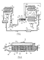
- a typical refrigeration system to which the method and apparatus of the invention can be applied comprises a refrigerant compressor 10 having a suction inlet 12 and a high pressure outlet 14, the compressor feeding the hot compressed refrigerant fluid via conduit 15 to a condenser coil 16 having an inlet 18 and an outlet 20. Cooled refrigerant from the coil 16 passes via conduit 21 to a liquid accumulator 22, and thence via conduit 24 through a filter/drier 26, a liquid indicator 28 and a common thermostatically controlled refrigerant flow control TX valve 30 into a distributor 32, from which it flows into two parallel-connected circuit coils 34a and 34b of an evaporator coil.
- Each circuit coil has an inlet 38a, 38b respectively and an outlet 40a and 40b respectively, the latter all being connected to a common header pipe 42 (sometimes also called a stand-pipe or manifold), the single outlet 44 of which is connected to inlet 46 of a turbulator and mixing device 48 of the invention.
- Asuperheat temperature sensing bulb 50 by which the TX valve 30 is controlled is tightly clamped to the exterior of the device 48 by a clamp 51 to be in good heat exchange with its interior and is connected by a capillary tube 52 to the valve 30.
- the outlet 54 of the device 48 is connected by conduit 56 to the pump inlet 12 to complete the system circuit.
- the usual fans 58 and 60 are provided to circulate ambient air over the coils 16 and 34a, 34b respectively.
- the numerous other circuit elements, controls and indicating devices that such a system normally includes do not constitute part of this invention and therefore do not need to be illustrated.
- the direction of flow of the refrigerent is indicated by the broken arrows.
- this particular device 48 is made of high conductivity metal, such as copper or brass, and consists of a first inner cylindrical pipe 62, one end of which is flanged and constitutes the inlet 46, and the other end 64 of which is closed.
- a second outer cylindrical pipe 66 of larger diameter surrounds the first inner pipe coaxial therewith and is sealed to the pipe at one end adjacent the inlet 46, while the other end is flanged and constitutes the oulet 54.
- the interior of the inner pipe is filled with a spirally wound coil 67 of stainless steel open mesh material.
- the inner pipe has a plurality of holes 68 distributed uniformly along its length and around its periphery, which holes direct the refrigerant vapour entering the inlet 46, together with any liquid entrained therein, forcibly against the inner wall of the outer pipe 66.
- the pipes and the bores therefore provide within the interior of the device a direction-changing flow path between the unlet and the outlet, the combination of the multitude of tortuous paths formed by the mesh coil 67, the abrupt changes in direction of the fast-flowing fluid, the turbulence in the inner pipe 62 because of the impingement of the fluid against the closed end, and the turbulence in the annular chamber 70 between the two pipes because of the said impingement against the outer pipe inner wall, ensuring that the entire refrigerant flow in the flow path, whether in the liquid or vapour phase, is all thoroughly mixed and rendered turbulent, and particularly without any possibility of the relatively high velocity vapour phase being able to flow through the device separately from the liquid phase.
- the vigorous impingement of the high velocity fluid against the outer pipe inner wall ensures that any relatively stagnant barrier layer of refrigerant, or of the lubricating oil that is always entrained therein, is thoroughly disrupted and removed from the inner wall, so that it cannot prevent the efficient transfer of heat from the refrigerant through the wall to the sensor bulb 50.
- the bulb is therefore sensing only the temperature of a completely turbulent mixed and temperature averaged refrigerant flow as received from the outlet of the headeer pipe 42, and in addition is much more sensitive to changes in the refrigerant temperature and more accurately measures the device interior temperature which corresponds to the averaged refrigerant temperature.
- This turbulating and mixing function of the device 48 is effective in this manner whatever the evaporator coil structure employed in the system.
- the device When the device is used with a system as specifically described, namely with multiple circuit coils, then in addition to turbulating and mixing the fluid flow in each evaporator circuit coil it also performs a multiple mixing function, whereby the fluid flows from all of the circuit coils are thoroughly mixed together, so that all of their separate temperatures are averaged, and it is this average circuit coil temperature that is detected by the bulb 50. Moreover, this very thorough turbulence and mixing ensures that if one or more of the circuit coils is not evaporating all of its supply of refrigerant, then the small quantities of liquid reaching the mixing device are immediately atomized and consequently easily vapourized by heat from the superheated vapour from the remaining coils. The supply of refrigerant to the strarved coil or coils can therefore be increased until the superheated vapour they produce is not able to vaporise the liquid refrigerant from the underloaded coil or coils.
- the diameters of the pipes 62 and 66 are such that the flow capacities of the resultant flow passages are about that of the remainder of the suction tube 56, while the number and size of the apertures 68 are such that about the same flow capacity is achieved.
- These flow capacities can vary between about 0.5 and 1.5 times the usual flow capacity of the suction tube; it may be preferred to reduce the flow capacity of the apertures 68 somewhat below that of the suction tube in order to obtain sufficiently forceful impingement of the fluid against the outer tube inner wall.
- the outer pipe 66 is about 20-25 cm (8-10 ins.) long and 4.0 cm. (1.6 ins.) outside diameter; the inner pipe 62 is 2.75 cm (1.1. in.) outside diameter and is provided with 40 uniformly spaced holes 68 of 0.47 cm (0.19 ins.) diameter.
- the mesh insert 67 consisted of a piece of stainless steel fine wire mesh corrugated diagonally to its length measuring 10cm by 15cm (4ins by 6ins) wound into a spiral sufficiently tightly to permit its insertion into the pipe, where it will expand to completely fill the space. It will be understood that it is not possible to accurately illustrate such a tightly rolled spiral in the drawings.
- the outer pipe 66 is 5.25 cm (2.1 in.) outside diameter
- the inner pipe 62 is 4.0 (1.6 in.) outside diameter
- the holes 68 are 0.6 cm (0.25 in.) diameter. It is found in practice that the pressure drop through the devices of the invention is sufficiently low, usually less than about 1 p.s.i., that it does not produce any appreciable loss of efficiency, and any loss for this reason is amply compensated by the overall considerably improved efficiencies that usually are obtained. The drop is sufficiently small that it is difficult, if not impossible, to detect with the pressure gauges that are used in standard refrigeration service practice.
- the refrigerant enters the coils as a low volume liquid and is evaporated in the confined spaces thereof to a high volume vapour, with the result that the exit speed of the vapour is relatively high, to the extent that in the absence of the highly positive turbulating and/or mixing method and corresponding apparatus of the invention, involving the entire fluid flow or flows, the flows in the coils remain laminar and any liquid particles remain entrained without mixing, while there is little or no opportunity for the flows from the different coils to mix and average.
- the theoretically ideal location is at 6 o'clock on the circumference of a horizontal suction pipe, where it should be able to sense most accurately any small quantity of liquid refrigerant passing in the pipe, and would therefore permit the smallest amount of superheat. In practice this has not been a satisfactory location because of the presence of lubricant oil in the refrigerant, which flows along the bottom of the pipe and would thermally insulate the sensor bulb from the refrigerant fluid. The usual location for the bulb has therefore been at four or eight o'clock on the pipe circumference.
- the location of the sensor bulb around the circumference of the device is quite immaterial, and it can be placed at the most convenient location from the point of view of installation as close to the valve as possible and subsequent access for service. It will also be seen that the sensor need not be located directly on the wall of the mixing device enclosure, which is the preferred location, but should be located as close as possible to the device outlet. In addition it is now found quite unnecessary to locate the sensor bulb on a horizontal portion of the suction line, and the attitude of the device has no effect upon its performance. It has also been found that the device is relatively insensitive to being installed so that the inlet is the outlet, and vice versa, although of course this is not recommended; a small decrease in efficiency of operation has been noted when this has occured.
- a device of the invention can readily be seen by visual inspection of the evaporator coil before and after its installation. Before installation it is usually found that the frost deposition on the different circuit coils is non-uniform with some of them completely frosted up to the outlet, while others are not frosted for a substantial distance back from the outlet, showing that the latter are starved of refrigerant and are working much below their maximum cooling capacity. Also the evaporator common outlet member is only partially frosted. With the device installed all of the circuit coils become more or less equally frosted, as well as the entire length of the suction manifold, indicating that all of the circuit coils are now operating at their full designed capacity.
- An important advantage that has been found to follow from use of the invention, demonstrating its unexpected nature, is the flexibility that is obtained upon installation in not having to closely match the size of the TX valve to the evaporator coil capacity without the valve losing control of the refrigerant flow.
- the capacity of a TX valve is determined both by the size of its flow aperture and the head pressure across the aperture, and it has been important in prior art installations for this match to be as close as possible.
- one manufacturer provides 21 different sizes of valve to cover the range 0.5-180 tons, those in the range 0.5 - 3 tons being rated in 0.5 ton increments, with progressively increasing intervals up to the maximum.
- valve If the valve is too large then with the high superheat values employed the valve hunts, overfeeding and underfeeding the evaporator with resultant poor efficiency and danger of liquid reaching the compressor because of the over-large flow capacity of the valve while open.
- valve and coil sizes closely matched it becomes necessary to maintain the head pressure above a minimum value, since otherwise the valve flow capacity becomes too low. This penalizes the system in winter when the air cooled condensers are very efficient and could operate with lower head pressure; instead it is necessary to maintain it artifically high by various techniques that are available. This means that the power required to compress the refrigerant must also be maintained at a corresponding high uneconomical value.
- the sensor bulb 50 preferably is installed on the device as close as possible to the device outlet 54 where the maximum mixing has occured.
- the external tube 66 is provided with an integral elongated neck portion 66a constituting the outlet 54 to facilitate fastening of the bulb to the device.
- the interior of the inner pipe 62 is completely filled with metallic wool 86 as a mixing medium, in place of the rolled screen of the embodiment of Figure 1
- Figure 4 shows another arrangement in which a second turbulating/mixing device 48b of the invention, of essentially the same body structure as the first device 48, now having the reference 48a, is connected in series with the first device, the sensor bulb 50 being installed on the downstream device 48a.
- the second device provides additional mixing with correspondingly improved performance of the TX valve, without too great an increase in pressure drop along the suction line, by suitable choice of the flow capacities of the respective internal passages and the bores 68.
- a mesh coil 67 (or body 86 of metallic wool) can be installed in either or both of the devices and is shown installed in device 48a.
- Figure 5 shows an embodiment in which the refrigerant flow path is provided by conduits forming two T-shaped junctions 74 and 76 connected by U-shaped connectors 78a and 78b; the connectors may be of smaller internal cross-section diameter to produce an increase in flow velocity of the refrigerant.
- the junction 74 divides the refrigerant flow from the common header 42 into two separate approximately equal sub-streams which are rendered turbulent by their impact against the transverse wall of the T cross-bar, the two streams moving separately at high velocity in the connectors 78a and 78b and being re-combined with a "head-on" collision in the cross-bar of the junction 76 back into a single stream.
- Figure 6 shows an arrangment in which the device 72 is followed by a device 48 so as to obtain the combined effect of the two devices, the bulb 50 being in this case attached to the downstream device 48.
- Figure 7 shows a further embodiment wherein the device consists of a container 80 having an inlet 82 for unturbulated, unmixed refrigerant and an outlet 84 for turbulent mixed refrigerant spaced from another along the length of the container, the inlet and outlet both being disposed radially with respect to the longitudinal axis of the container, so that abrupt changes in direction of the fluid flow path are produced.
- the interior of the container is filled with a porous turbulating and mixing medium 86 through which all of the refrigerant must pass in moving from the inlet to the outlet.
- the movement of the refrigerant fluid through the myriad of random interconnected channels in the medium 86 ensures the necessary thorough turbulence and/or mixing thereof.
- a suitable medium is for example metallic wools, foams or screens, or other suitable metallic media, particularly of stainless steel or aluminum, packed sufficiently densely to achieve the desired amount of turbulence and mixing without too great a pressure drop.
- Other media such as open-celled porous plastic and ceramic foams can also be used.
- Sensor bulb 50 is firmly clamped to the container exterior wall, which is sufficiently heat conductive, as close as possible to the outlet 84.
- the container 80 was 10cm (4ins) in diameter and 25cm (10ins) long and was packed with stainless steel wool.
- the body of wool is surrounded by at least a single layer of wire mesh to ensure that pieces of the wool cannot break off and enter the system.
- Figure 8 shows an arrangement in which the device 80 of Figure 7 is used as a pre-turbulator and pre-mixer for a second downstream device 48, so as again to obtain the combined effect of the two devices.
- Figure 9 shows an embodiment in which the device comprises a straight length of pipe 66 the whole interior of which is filled with closely wound wire mesh 67, so that again the entire refrigerant flow is intercepted, rendered sufficiently turbulent and mixed to the necessary extent.
- the device preferably is made much longer so as to provide a longer path than with the previously described turbulating and mixing devices, the sensor bulb 50 being attached, as with the other embodiments, as close as possible to the outlet end 54.
- the additional length required a device fitted in a system with a compressor of 10 H.P.
- a device with a straight enclosure between the inlet and the outlet consisted of a piece of pipe 25cm (10 in) long and 4cm (1.6 in) outside diameter.
- the device was employed with a coil of about 10 H.P. capacity with the sensor bulb fastened to the suction line immediately downstream of the device. Despite its relatively short length it still resulted in an increase of approximately 20% in the cooling capacity of the coil.
Landscapes
- Engineering & Computer Science (AREA)
- Physics & Mathematics (AREA)
- Mechanical Engineering (AREA)
- Thermal Sciences (AREA)
- General Engineering & Computer Science (AREA)
- Chemical & Material Sciences (AREA)
- Analytical Chemistry (AREA)
- Power Engineering (AREA)
- Devices That Are Associated With Refrigeration Equipment (AREA)
- Filling Or Discharging Of Gas Storage Vessels (AREA)
- Temperature-Responsive Valves (AREA)
- Heat-Exchange Devices With Radiators And Conduit Assemblies (AREA)
Priority Applications (1)
| Application Number | Priority Date | Filing Date | Title |
|---|---|---|---|
| AT89307902T ATE96220T1 (de) | 1988-08-04 | 1989-08-03 | Vorrichtung zur erfassung der kaeltemitteltemperatur zur steuerung eines verdampferventils. |
Applications Claiming Priority (2)
| Application Number | Priority Date | Filing Date | Title |
|---|---|---|---|
| US22903888A | 1988-08-04 | 1988-08-04 | |
| US229038 | 1988-08-04 |
Publications (3)
| Publication Number | Publication Date |
|---|---|
| EP0354037A2 true EP0354037A2 (fr) | 1990-02-07 |
| EP0354037A3 EP0354037A3 (fr) | 1991-02-27 |
| EP0354037B1 EP0354037B1 (fr) | 1993-10-20 |
Family
ID=22859591
Family Applications (1)
| Application Number | Title | Priority Date | Filing Date |
|---|---|---|---|
| EP89307902A Expired - Lifetime EP0354037B1 (fr) | 1988-08-04 | 1989-08-03 | Dispositif pour le palpage de la température de réfrigérant pour le contrôle d'une soupape d'un évaporateur |
Country Status (6)
| Country | Link |
|---|---|
| EP (1) | EP0354037B1 (fr) |
| JP (1) | JPH02238255A (fr) |
| AT (1) | ATE96220T1 (fr) |
| AU (1) | AU624852B2 (fr) |
| CA (1) | CA1330261C (fr) |
| DE (1) | DE68910041T2 (fr) |
Cited By (9)
| Publication number | Priority date | Publication date | Assignee | Title |
|---|---|---|---|---|
| WO1991008427A1 (fr) * | 1989-11-29 | 1991-06-13 | Super S.E.E.R. Systems Inc. | Appareil de detection des temperatures refrigerantes |
| FR2836211A1 (fr) * | 2002-02-18 | 2003-08-22 | Valeo Climatisation | Separateur liquide/vapeur dans une boucle de climatisation |
| WO2008151629A1 (fr) * | 2007-06-12 | 2008-12-18 | Danfoss A/S | Procédé permettant de commander une distribution d'un fluide frigorigène |
| DE102011107538A1 (de) * | 2011-06-10 | 2012-12-13 | Liebherr-Hausgeräte Ochsenhausen GmbH | Kühl- und/oder Gefriergerät |
| US8584484B2 (en) | 2007-08-31 | 2013-11-19 | Airbus Operations Gmbh | Aircraft cooling system evaporator arrangement for two mutually independent coolant circuits |
| CN109186282A (zh) * | 2018-08-24 | 2019-01-11 | 深圳市贝腾科技有限公司 | 热交换装置及冷冻干燥设备 |
| WO2020076333A1 (fr) * | 2018-10-11 | 2020-04-16 | Custom Controls Company | Dispositif de régulation de la puissance frigorifique |
| US10753657B2 (en) | 2018-10-11 | 2020-08-25 | Custom Controls Company, a Texas corporation | Refrigeration capacity control device |
| EP3789693A1 (fr) * | 2019-09-06 | 2021-03-10 | Hamilton Sundstrand Corporation | Système de réfrigération et procédé associé |
Families Citing this family (1)
| Publication number | Priority date | Publication date | Assignee | Title |
|---|---|---|---|---|
| DE102023125931A1 (de) * | 2023-09-25 | 2025-03-27 | Rheinmetall Invent GmbH | Wärmetauscher |
Family Cites Families (4)
| Publication number | Priority date | Publication date | Assignee | Title |
|---|---|---|---|---|
| DE1068734B (fr) * | 1959-11-12 | |||
| US2960845A (en) * | 1958-01-31 | 1960-11-22 | Sporlan Valve Co | Refrigerant control for systems with variable head pressure |
| SE410221B (sv) * | 1978-02-07 | 1979-10-01 | T Brandin | Atgerd vid kylanleggning for att forhindra att koldmedium i vetskeform nar kompressorn |
| GB2164438B (en) * | 1984-09-14 | 1988-07-27 | Aisin Seiki | Heat exchangers |
-
1989
- 1989-07-27 CA CA000606876A patent/CA1330261C/fr not_active Expired - Lifetime
- 1989-08-03 AT AT89307902T patent/ATE96220T1/de not_active IP Right Cessation
- 1989-08-03 EP EP89307902A patent/EP0354037B1/fr not_active Expired - Lifetime
- 1989-08-03 DE DE89307902T patent/DE68910041T2/de not_active Expired - Fee Related
- 1989-08-04 JP JP1201476A patent/JPH02238255A/ja active Pending
- 1989-08-17 AU AU40019/89A patent/AU624852B2/en not_active Ceased
Cited By (15)
| Publication number | Priority date | Publication date | Assignee | Title |
|---|---|---|---|---|
| WO1991008427A1 (fr) * | 1989-11-29 | 1991-06-13 | Super S.E.E.R. Systems Inc. | Appareil de detection des temperatures refrigerantes |
| WO1991008428A1 (fr) * | 1989-11-29 | 1991-06-13 | Super S.E.E.R. Systems Inc. | Appareil de detection des temperatures refrigerantes |
| FR2836211A1 (fr) * | 2002-02-18 | 2003-08-22 | Valeo Climatisation | Separateur liquide/vapeur dans une boucle de climatisation |
| WO2003071202A1 (fr) * | 2002-02-18 | 2003-08-28 | Valeo Climatisation | Séparateur liquide/vapeur dans une boucle de climatisation |
| CN101765750B (zh) * | 2007-06-12 | 2012-03-21 | 丹福斯有限公司 | 控制制冷剂分配的方法 |
| RU2413908C1 (ru) * | 2007-06-12 | 2011-03-10 | Данфосс А/С | Способ регулирования распределения хладагента |
| WO2008151629A1 (fr) * | 2007-06-12 | 2008-12-18 | Danfoss A/S | Procédé permettant de commander une distribution d'un fluide frigorigène |
| US8769976B2 (en) | 2007-06-12 | 2014-07-08 | Danfoss A/S | Method for controlling a refrigerant distribution |
| US8584484B2 (en) | 2007-08-31 | 2013-11-19 | Airbus Operations Gmbh | Aircraft cooling system evaporator arrangement for two mutually independent coolant circuits |
| DE102011107538A1 (de) * | 2011-06-10 | 2012-12-13 | Liebherr-Hausgeräte Ochsenhausen GmbH | Kühl- und/oder Gefriergerät |
| CN109186282A (zh) * | 2018-08-24 | 2019-01-11 | 深圳市贝腾科技有限公司 | 热交换装置及冷冻干燥设备 |
| WO2020076333A1 (fr) * | 2018-10-11 | 2020-04-16 | Custom Controls Company | Dispositif de régulation de la puissance frigorifique |
| US10753657B2 (en) | 2018-10-11 | 2020-08-25 | Custom Controls Company, a Texas corporation | Refrigeration capacity control device |
| EP3789693A1 (fr) * | 2019-09-06 | 2021-03-10 | Hamilton Sundstrand Corporation | Système de réfrigération et procédé associé |
| US11498686B2 (en) | 2019-09-06 | 2022-11-15 | Hamilton Sundstrand Corporation | Refrigeration systems |
Also Published As
| Publication number | Publication date |
|---|---|
| CA1330261C (fr) | 1994-06-21 |
| ATE96220T1 (de) | 1993-11-15 |
| AU624852B2 (en) | 1992-06-25 |
| JPH02238255A (ja) | 1990-09-20 |
| EP0354037B1 (fr) | 1993-10-20 |
| DE68910041T2 (de) | 1994-05-11 |
| DE68910041D1 (de) | 1993-11-25 |
| AU4001989A (en) | 1991-04-18 |
| EP0354037A3 (fr) | 1991-02-27 |
Similar Documents
| Publication | Publication Date | Title |
|---|---|---|
| US5040380A (en) | Method and apparatus for the sensing of refrigerant temperatures and the control of refrigerant loading | |
| US5052190A (en) | Apparatus for the sensing of refrigerant temperatures and the control of refrigerant loading | |
| US5622055A (en) | Liquid over-feeding refrigeration system and method with integrated accumulator-expander-heat exchanger | |
| US4696168A (en) | Refrigerant subcooler for air conditioning systems | |
| US2229940A (en) | Refrigerant distributor for cooling units | |
| EP0541343B1 (fr) | Systèmes de réfrigération | |
| US4949551A (en) | Hot gas defrost system for refrigeration systems | |
| EP0354037B1 (fr) | Dispositif pour le palpage de la température de réfrigérant pour le contrôle d'une soupape d'un évaporateur | |
| US5692387A (en) | Liquid cooling of discharge gas | |
| US4811568A (en) | Refrigeration sub-cooler | |
| US3481151A (en) | Refrigerant system employing liquid chilling evaporators | |
| EP1287298A1 (fr) | Systeme de regulation du degre de surchauffe d'un appareil de conditionnement d'air et son procede de regulation | |
| DE60031565T2 (de) | Dampfkompressionssystem und verfahren zur steuerung der umgebungsverhältnisse | |
| US8783057B2 (en) | Refrigerant distributor | |
| US2148413A (en) | Refrigerating apparatus | |
| US3877248A (en) | Refrigerant expansion device | |
| US6389825B1 (en) | Evaporator coil with multiple orifices | |
| US5860287A (en) | Coolness storage for fixed capacity refrigeration system | |
| US4718245A (en) | Refrigeration system with bypass valves | |
| US5157935A (en) | Hot gas defrost system for refrigeration systems and apparatus therefor | |
| US2063380A (en) | Refrigerant distributor | |
| US3552140A (en) | Refrigeration system with accumulator | |
| EP0502883B1 (fr) | Appareil de detection des temperatures refrigerantes | |
| EP0751391A1 (fr) | Capteur des liquides et méthode | |
| US4807449A (en) | Latent heat economizing device for refrigeration systems |
Legal Events
| Date | Code | Title | Description |
|---|---|---|---|
| PUAI | Public reference made under article 153(3) epc to a published international application that has entered the european phase |
Free format text: ORIGINAL CODE: 0009012 |
|
| AK | Designated contracting states |
Kind code of ref document: A2 Designated state(s): AT BE CH DE ES FR GB GR IT LI LU NL SE |
|
| PUAL | Search report despatched |
Free format text: ORIGINAL CODE: 0009013 |
|
| AK | Designated contracting states |
Kind code of ref document: A3 Designated state(s): AT BE CH DE ES FR GB GR IT LI LU NL SE |
|
| 17P | Request for examination filed |
Effective date: 19910813 |
|
| 17Q | First examination report despatched |
Effective date: 19920117 |
|
| RAP1 | Party data changed (applicant data changed or rights of an application transferred) |
Owner name: SUPER S.E.E.R. SYSTEMS INC. |
|
| GRAA | (expected) grant |
Free format text: ORIGINAL CODE: 0009210 |
|
| AK | Designated contracting states |
Kind code of ref document: B1 Designated state(s): AT BE CH DE ES FR GB GR IT LI LU NL SE |
|
| PG25 | Lapsed in a contracting state [announced via postgrant information from national office to epo] |
Ref country code: SE Effective date: 19931020 Ref country code: NL Effective date: 19931020 Ref country code: LI Effective date: 19931020 Ref country code: GR Free format text: LAPSE BECAUSE OF FAILURE TO SUBMIT A TRANSLATION OF THE DESCRIPTION OR TO PAY THE FEE WITHIN THE PRESCRIBED TIME-LIMIT Effective date: 19931020 Ref country code: ES Free format text: THE PATENT HAS BEEN ANNULLED BY A DECISION OF A NATIONAL AUTHORITY Effective date: 19931020 Ref country code: CH Effective date: 19931020 Ref country code: BE Effective date: 19931020 Ref country code: AT Effective date: 19931020 |
|
| REF | Corresponds to: |
Ref document number: 96220 Country of ref document: AT Date of ref document: 19931115 Kind code of ref document: T |
|
| REF | Corresponds to: |
Ref document number: 68910041 Country of ref document: DE Date of ref document: 19931125 |
|
| ITF | It: translation for a ep patent filed | ||
| REG | Reference to a national code |
Ref country code: CH Ref legal event code: PL |
|
| ET | Fr: translation filed | ||
| NLV1 | Nl: lapsed or annulled due to failure to fulfill the requirements of art. 29p and 29m of the patents act | ||
| PLBE | No opposition filed within time limit |
Free format text: ORIGINAL CODE: 0009261 |
|
| STAA | Information on the status of an ep patent application or granted ep patent |
Free format text: STATUS: NO OPPOSITION FILED WITHIN TIME LIMIT |
|
| PG25 | Lapsed in a contracting state [announced via postgrant information from national office to epo] |
Ref country code: LU Free format text: LAPSE BECAUSE OF NON-PAYMENT OF DUE FEES Effective date: 19940831 |
|
| 26N | No opposition filed | ||
| REG | Reference to a national code |
Ref country code: GB Ref legal event code: IF02 |
|
| PGFP | Annual fee paid to national office [announced via postgrant information from national office to epo] |
Ref country code: GB Payment date: 20020731 Year of fee payment: 14 |
|
| PGFP | Annual fee paid to national office [announced via postgrant information from national office to epo] |
Ref country code: DE Payment date: 20020807 Year of fee payment: 14 |
|
| PGFP | Annual fee paid to national office [announced via postgrant information from national office to epo] |
Ref country code: FR Payment date: 20020808 Year of fee payment: 14 |
|
| PG25 | Lapsed in a contracting state [announced via postgrant information from national office to epo] |
Ref country code: GB Free format text: LAPSE BECAUSE OF NON-PAYMENT OF DUE FEES Effective date: 20030803 |
|
| PG25 | Lapsed in a contracting state [announced via postgrant information from national office to epo] |
Ref country code: DE Free format text: LAPSE BECAUSE OF NON-PAYMENT OF DUE FEES Effective date: 20040302 |
|
| GBPC | Gb: european patent ceased through non-payment of renewal fee |
Effective date: 20030803 |
|
| PG25 | Lapsed in a contracting state [announced via postgrant information from national office to epo] |
Ref country code: FR Free format text: LAPSE BECAUSE OF NON-PAYMENT OF DUE FEES Effective date: 20040430 |
|
| REG | Reference to a national code |
Ref country code: FR Ref legal event code: ST |
|
| PG25 | Lapsed in a contracting state [announced via postgrant information from national office to epo] |
Ref country code: IT Free format text: LAPSE BECAUSE OF NON-PAYMENT OF DUE FEES;WARNING: LAPSES OF ITALIAN PATENTS WITH EFFECTIVE DATE BEFORE 2007 MAY HAVE OCCURRED AT ANY TIME BEFORE 2007. THE CORRECT EFFECTIVE DATE MAY BE DIFFERENT FROM THE ONE RECORDED. Effective date: 20050803 |