EP0354054A2 - Regelsystem für Turbolader - Google Patents
Regelsystem für Turbolader Download PDFInfo
- Publication number
- EP0354054A2 EP0354054A2 EP89307947A EP89307947A EP0354054A2 EP 0354054 A2 EP0354054 A2 EP 0354054A2 EP 89307947 A EP89307947 A EP 89307947A EP 89307947 A EP89307947 A EP 89307947A EP 0354054 A2 EP0354054 A2 EP 0354054A2
- Authority
- EP
- European Patent Office
- Prior art keywords
- engine
- turbocharger
- intake air
- accelerator pedal
- intake
- Prior art date
- Legal status (The legal status is an assumption and is not a legal conclusion. Google has not performed a legal analysis and makes no representation as to the accuracy of the status listed.)
- Granted
Links
Images
Classifications
-
- F—MECHANICAL ENGINEERING; LIGHTING; HEATING; WEAPONS; BLASTING
- F02—COMBUSTION ENGINES; HOT-GAS OR COMBUSTION-PRODUCT ENGINE PLANTS
- F02B—INTERNAL-COMBUSTION PISTON ENGINES; COMBUSTION ENGINES IN GENERAL
- F02B39/00—Component parts, details, or accessories relating to, driven charging or scavenging pumps, not provided for in groups F02B33/00 - F02B37/00
- F02B39/02—Drives of pumps; Varying pump drive gear ratio
- F02B39/08—Non-mechanical drives, e.g. fluid drives having variable gear ratio
- F02B39/10—Non-mechanical drives, e.g. fluid drives having variable gear ratio electric
-
- F—MECHANICAL ENGINEERING; LIGHTING; HEATING; WEAPONS; BLASTING
- F02—COMBUSTION ENGINES; HOT-GAS OR COMBUSTION-PRODUCT ENGINE PLANTS
- F02B—INTERNAL-COMBUSTION PISTON ENGINES; COMBUSTION ENGINES IN GENERAL
- F02B21/00—Engines characterised by air-storage chambers
-
- F—MECHANICAL ENGINEERING; LIGHTING; HEATING; WEAPONS; BLASTING
- F02—COMBUSTION ENGINES; HOT-GAS OR COMBUSTION-PRODUCT ENGINE PLANTS
- F02B—INTERNAL-COMBUSTION PISTON ENGINES; COMBUSTION ENGINES IN GENERAL
- F02B33/00—Engines characterised by provision of pumps for charging or scavenging
- F02B33/44—Passages conducting the charge from the pump to the engine inlet, e.g. reservoirs
-
- F—MECHANICAL ENGINEERING; LIGHTING; HEATING; WEAPONS; BLASTING
- F02—COMBUSTION ENGINES; HOT-GAS OR COMBUSTION-PRODUCT ENGINE PLANTS
- F02B—INTERNAL-COMBUSTION PISTON ENGINES; COMBUSTION ENGINES IN GENERAL
- F02B33/00—Engines characterised by provision of pumps for charging or scavenging
- F02B33/44—Passages conducting the charge from the pump to the engine inlet, e.g. reservoirs
- F02B33/446—Passages conducting the charge from the pump to the engine inlet, e.g. reservoirs having valves for admission of atmospheric air to engine, e.g. at starting
-
- F—MECHANICAL ENGINEERING; LIGHTING; HEATING; WEAPONS; BLASTING
- F02—COMBUSTION ENGINES; HOT-GAS OR COMBUSTION-PRODUCT ENGINE PLANTS
- F02B—INTERNAL-COMBUSTION PISTON ENGINES; COMBUSTION ENGINES IN GENERAL
- F02B37/00—Engines characterised by provision of pumps driven at least for part of the time by exhaust
- F02B37/04—Engines with exhaust drive and other drive of pumps, e.g. with exhaust-driven pump and mechanically-driven second pump
- F02B37/10—Engines with exhaust drive and other drive of pumps, e.g. with exhaust-driven pump and mechanically-driven second pump at least one pump being alternatively or simultaneously driven by exhaust and other drive, e.g. by pressurised fluid from a reservoir or an engine-driven pump
-
- F—MECHANICAL ENGINEERING; LIGHTING; HEATING; WEAPONS; BLASTING
- F02—COMBUSTION ENGINES; HOT-GAS OR COMBUSTION-PRODUCT ENGINE PLANTS
- F02B—INTERNAL-COMBUSTION PISTON ENGINES; COMBUSTION ENGINES IN GENERAL
- F02B37/00—Engines characterised by provision of pumps driven at least for part of the time by exhaust
- F02B37/12—Control of the pumps
- F02B37/14—Control of the alternation between or the operation of exhaust drive and other drive of a pump, e.g. dependent on speed
-
- F—MECHANICAL ENGINEERING; LIGHTING; HEATING; WEAPONS; BLASTING
- F02—COMBUSTION ENGINES; HOT-GAS OR COMBUSTION-PRODUCT ENGINE PLANTS
- F02B—INTERNAL-COMBUSTION PISTON ENGINES; COMBUSTION ENGINES IN GENERAL
- F02B37/00—Engines characterised by provision of pumps driven at least for part of the time by exhaust
- F02B37/12—Control of the pumps
- F02B37/22—Control of the pumps by varying cross-section of exhaust passages or air passages, e.g. by throttling turbine inlets or outlets or by varying effective number of guide conduits
-
- Y—GENERAL TAGGING OF NEW TECHNOLOGICAL DEVELOPMENTS; GENERAL TAGGING OF CROSS-SECTIONAL TECHNOLOGIES SPANNING OVER SEVERAL SECTIONS OF THE IPC; TECHNICAL SUBJECTS COVERED BY FORMER USPC CROSS-REFERENCE ART COLLECTIONS [XRACs] AND DIGESTS
- Y02—TECHNOLOGIES OR APPLICATIONS FOR MITIGATION OR ADAPTATION AGAINST CLIMATE CHANGE
- Y02T—CLIMATE CHANGE MITIGATION TECHNOLOGIES RELATED TO TRANSPORTATION
- Y02T10/00—Road transport of goods or passengers
- Y02T10/10—Internal combustion engine [ICE] based vehicles
- Y02T10/12—Improving ICE efficiencies
Definitions
- the present invention relates to a turbocharger control system for controlling a turbocharger including an electric motor mounted on a rotatable shaft which interconnects a turbine and a compressor, so that a motor vehicle incorporating the turbocharger can quickly be re-accelerated after the motor vehicle has been subjected to engine braking.
- turbochargers which introduce exhaust gases from an engine to an exhaust turbine to rotate the turbine at a high speed, and pressurize intake air with a compressor directly coupled to the exhaust turbine for thereby supercharging the engine.
- Japanese Laid-Open Patent Publication No. 60-195329 discloses an apparatus in which a rotary electric machine is mounted on the rotatable shaft of such a turbocharger and operable as an electric motor or generator depending on the operating condition of the engine. At least when the engine operates at a low speed and under a high load, the rotary electric machine is operated as the motor or the generator to drive the compressor for supercharging the engine.
- the boost pressure is increased and the torque produced by the engine is increased.
- the boost pressure cannot be increased as quickly as it is desired to accelerate the engine since the rotational parts such as the motor and the compressor have moments of inertia and it takes time to compress air.
- a turbocharger control system including valves disposed respectively in the opposite ends of an intake passage which interconnects the compressor of a turbocharger and an engine, the valves being used to keep compressed air in the intake passage and to supply the compressed air quickly into the engine when the engine is to be re-accelerated.
- a system for controlling a turbocharger associated with an engine comprising storing means for closing a passage interconnecting an air outlet of the turbocharger and an air inlet of the engine and storing intake air from the turbocharger, supply means for supplying intake air stored by the storing means into the engine, detecting means for detecting the amount of depression of an accelerator pedal which controls the output power of the engine, means for operating the storing means when it is determined based on a signal from the detecting means that the accelerator pedal is released at a speed higher than a predetermined speed, and means for operating the supply means when it is determined that the accelerator pedal is depressed when the storing means is operated.
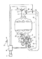
- the sole figure is a schematic diagram, partly shown in block form, of a turbocharger control system according to the present invention.
- An engine 1 mounted on a motor vehicle drives the motor vehicle with the combustion energy produced by burning a mixture of fuel and air which is introduced into the engine through an intake pipe 11.
- Exhaust gases from the engine 1 are supplied through an exhaust pipe 12 into a turbocharger 2 coupled to the engine 1.
- the exhaust pipe 12 is divided into two sections, one of which can be opened and closed by an exhaust pipe valve 23 disposed therein.
- the exhaust pipe valve 23 is opened and closed by a valve actuator 24.
- the turbocharger 2 has an exhaust turbine 21 and an intake compressor 22 coupled to the exhaust turbine 21 by a rotatable shaft thereof.
- the intake compressor 22 is rotated by the torque produced by the exhaust turbine 21 for compressing intake air.
- the intake compressor 22 has an outlet connected to the intake pipe 11 through an intake passage 13 for feeding air under pressure to the intake pipe 11 to supercharge the engine 1.
- a reed valve 14 is disposed between the outlet of the compressor 22 and the intake passage 13.
- the reed valve 14 comprises a one-way valve capable of allowing air to flow freely from the compressor 22 into the intake passage 13, but is hermetically sealed against an air flow from the intake passage 13 toward the compressor 22.
- the reed valve 14 may be replaced with a butterfly valve which is openable and closable by an actuator.
- a butterfly valve 15 is disposed in the terminal end of the intake passage 13, i.e., between the intake passage 13 and the intake pipe 11.
- the butterfly valve 15 is openable and closable by a valve actuator 16.
- a pressure sensor 19 for detecting the pressure inside the intake passage 13 is mounted in the intake passage 19.
- the inlet end of the intake pipe 11 can be opened and closed by an intake pipe valve 17 which is openable and closable by a valve actuator 18.
- a rotary electric machine 3 is mounted on the rotatable shaft by which the exhaust turbine 21 and the intake compressor 22 are directly coupled to each other.
- the rotary electric machine 3 operates as an electric motor to drive the intake compressor 22 for assisting supercharging operation of the turbocharger 2.
- the rotary electric machine 3 operates as an electric generator to produce electric power.
- Stored electric power is supplied from a battery 4 through a controller 6 to the rotary electric machine 3 to operate the rotary electric machine 3 as the motor.
- An accelerator pedal 5 is associated with an accelerator pedal movement sensor 51 which serves as a means for detecting the amount of depression of the accelerator pedal 5.
- the accelerator pedal movement sensor 51 detects the movement of the accelerator pedal 5 depressed by the driver of the motor vehicle, and sends a signal indicative of the detected movement to the controller 6.
- the controller 6 comprises a microcomputer including a central processing unit for effecting arithmetic operations, various memories for storing arithmetic and control procedures, and input/output ports, and a power converter for converting DC electric power from the battery 4 to AC electric power having a certain frequency.
- the controller 6 is supplied with detected signals from the pressure sensor 19 and the accelerator pedal movement sensor 51, applies control signals to the valve actuators 16, 18, 24, and supplies AC electric power to the rotary electric machine 3.
- the butterfly valve 15 When the engine 1 operates under a low load, the butterfly valve 15 is opened as the rate of flow of exhaust gases from the engine 1 is low and the engine 1 is not supercharged by the compressor 22.
- the intake valve 17 is opened. Intake air compressed by the compressor 22 is supplied through the butterfly valve 15 into the engine 1.
- the accelerator pedal movement sensor 51 detects the release of the accelerator pedal 5. The controller 6 then determines that the motor vehicle is to be subjected to engine braking based on a signal from the accelerator pedal movement sensor 51.
- the controller 6 When the controller 6 detects the engine braking operation, it supplies control signals to the valve actuators 16, 18, 24 to close the butterfly valve 15 and the exhaust pipe valve 23 and open the intake pipe valve 17. When the exhaust pipe valve 23 is closed, the resistance to the flow of exhaust gases is increased, thereby exerting engine braking to the motor vehicle.
- the controller 6 detects the depression of the accelerator pedal 6, and send control signals to close the intake pipe valve 17 and open the exhaust pipe valve 24.
- the controller 6 adjusts the opening of the butterfly valve 15 depending on the signals from the accelerator pedal movement sensor 51 and the pressure sensor 19.
- the intake air stored in the intake passage 13 is then supplied immediately to the engine 1.
- the opening of the butterfly valve 15 is adjusted such that when the accelerator pedal 5 is depressed to a large extent, the butterfly valve 15 is fully opened, and when the accelerator pedal 5 is depressed to a small extent, the opening of the butterfly valve 15 is reduced. As the pressure indicated by the signal from the pressure sensor 19 is reduced, the controller 6 increases the opening of the butterfly valve 15.
- the DC electric power from the battery 4 is converted by the power converter in the controller 6 into AC electric power having a certain frequency which is then supplied to the rotary electric machine 3.
- the rotary electric machine 3 is then operated as the motor to rotate the intake compressor 22 so that sufficient air under pressure can be fed through the reed valve 14 and stored in the intake passage 13.
- An accumulator may be disposed in the intake passage 13, and pressurized air may be stored in the accumulator when the motor vehicle is subjected to engine braking.
- the butterfly valve and the reed valve for closing the intake passage are disposed respectively in the opposite ends of the intake passage by which the turbocharger and the intake pipe of the engine are interconnected.
- Intake air under pressure is stored in the closed intake passage by the energy of exhaust gases discharged from the engine when the motor vehicle undergoes engine braking.
- the stored intake air under pressure is quickly supplied to the engine at a rate commensurate with the amount of depression of the accelerator pedal. Therefore, the engine can be accelerated quickly and its rotation speed can be increased quickly.
- the electric power from the battery is supplied to the rotary electric machine to drive the intake compressor. Accordingly, sufficient air under pressure can be stored in the intake passage to allow the engine to be accelerated highly quickly.
Landscapes
- Engineering & Computer Science (AREA)
- Chemical & Material Sciences (AREA)
- Combustion & Propulsion (AREA)
- Mechanical Engineering (AREA)
- General Engineering & Computer Science (AREA)
- Supercharger (AREA)
Applications Claiming Priority (2)
| Application Number | Priority Date | Filing Date | Title |
|---|---|---|---|
| JP63195719A JP2622994B2 (ja) | 1988-08-05 | 1988-08-05 | 回転電機付ターボチャージャの制御装置 |
| JP195719/88 | 1988-08-05 |
Publications (3)
| Publication Number | Publication Date |
|---|---|
| EP0354054A2 true EP0354054A2 (de) | 1990-02-07 |
| EP0354054A3 EP0354054A3 (en) | 1990-12-27 |
| EP0354054B1 EP0354054B1 (de) | 1994-04-20 |
Family
ID=16345829
Family Applications (1)
| Application Number | Title | Priority Date | Filing Date |
|---|---|---|---|
| EP89307947A Expired - Lifetime EP0354054B1 (de) | 1988-08-05 | 1989-08-04 | Regelsystem für Turbolader |
Country Status (4)
| Country | Link |
|---|---|
| US (1) | US4998951A (de) |
| EP (1) | EP0354054B1 (de) |
| JP (1) | JP2622994B2 (de) |
| DE (1) | DE68914746T2 (de) |
Cited By (4)
| Publication number | Priority date | Publication date | Assignee | Title |
|---|---|---|---|---|
| WO2003044348A1 (de) * | 2001-11-20 | 2003-05-30 | Schatz Thermo Engineering | Verfahren zum ladungswechsel bei einem verbrennungsmotor der kolbenbauart und zur durchführung des verfahrens geeignetes ladungswechselsystem |
| EP1355052A1 (de) * | 2002-04-15 | 2003-10-22 | Ford Global Technologies, Inc., A subsidiary of Ford Motor Company | Ladesystem für eine Brennkraftmaschine sowie Verfahren zu dessen Regelung |
| EP1367237A1 (de) * | 2002-05-29 | 2003-12-03 | Toyota Jidosha Kabushiki Kaisha | Vorrichtung und Verfahren zur Steuerung von Kraftfahrzeugen |
| WO2005064134A1 (de) * | 2003-12-31 | 2005-07-14 | Birgit Bergmann | Turboloch (ladeunterstützung mit speicher) |
Families Citing this family (31)
| Publication number | Priority date | Publication date | Assignee | Title |
|---|---|---|---|---|
| JP2840916B2 (ja) * | 1994-03-02 | 1998-12-24 | 株式会社 フォーバル | ファクシミリ一体型端末装置 |
| US6256993B1 (en) | 1995-07-28 | 2001-07-10 | Honeywell International, Inc. | Motor-assisted variable geometry turbocharging system |
| US5560208A (en) * | 1995-07-28 | 1996-10-01 | Halimi; Edward M. | Motor-assisted variable geometry turbocharging system |
| US6029452A (en) | 1995-11-15 | 2000-02-29 | Turbodyne Systems, Inc. | Charge air systems for four-cycle internal combustion engines |
| US5808460A (en) * | 1997-09-29 | 1998-09-15 | Texas Instruments Incorporated | Rapid power enabling circuit |
| US6032466A (en) * | 1996-07-16 | 2000-03-07 | Turbodyne Systems, Inc. | Motor-assisted turbochargers for internal combustion engines |
| US5787711A (en) * | 1996-09-16 | 1998-08-04 | Turbodyne Systems, Inc. | Motor-assisted turbo-cooling system for internal combustion engines |
| US5819538A (en) * | 1996-11-15 | 1998-10-13 | Lawson, Jr.; Thomas Towles | Turbocharged engine system with recirculation and supplemental air supply |
| KR100271467B1 (ko) * | 1996-12-12 | 2000-11-15 | 정몽규 | 배기터빈과급기엔진의저속보상장치 |
| US5904471A (en) * | 1996-12-20 | 1999-05-18 | Turbodyne Systems, Inc. | Cooling means for a motor-driven centrifugal air compressor |
| US5857332A (en) * | 1996-12-20 | 1999-01-12 | Turbodyne Systems, Inc. | Bearing systems for motor-assisted turbochargers for internal combustion engines |
| US5867987A (en) * | 1997-02-25 | 1999-02-09 | Turbodyne Systems, Inc. | Method and apparatus for combined improved engine operation, warm-up and braking |
| US6085527A (en) * | 1997-05-15 | 2000-07-11 | Turbodyne Systems, Inc. | Magnet assemblies for motor-assisted turbochargers |
| US6062026A (en) * | 1997-05-30 | 2000-05-16 | Turbodyne Systems, Inc. | Turbocharging systems for internal combustion engines |
| US6135731A (en) * | 1997-06-26 | 2000-10-24 | Turbodyne Systems, Inc. | Compact and self-cooling blower assembly |
| US6079211A (en) * | 1997-08-14 | 2000-06-27 | Turbodyne Systems, Inc. | Two-stage supercharging systems for internal combustion engines |
| US6145314A (en) * | 1998-09-14 | 2000-11-14 | Turbodyne Systems, Inc. | Compressor wheels and magnet assemblies for internal combustion engine supercharging devices |
| DE10022208A1 (de) * | 2000-05-06 | 2001-11-08 | Pierburg Ag | Sekundärluftgebläse für eine Brennkraftmaschine |
| US6769411B2 (en) * | 2002-09-23 | 2004-08-03 | Sandor C. Fabiani | Nozzle air injection system for a fuel-injected engine |
| US20080121218A1 (en) * | 2004-12-13 | 2008-05-29 | Caterpillar Inc. | Electric turbocompound control system |
| US7174714B2 (en) * | 2004-12-13 | 2007-02-13 | Caterpillar Inc | Electric turbocompound control system |
| JP2006207417A (ja) * | 2005-01-26 | 2006-08-10 | Denso Corp | 過給機付エンジン制御システム |
| US7661417B2 (en) * | 2006-03-28 | 2010-02-16 | Advanced Global Equities And Intellectual Properties, Inc. | Air pressure boost assist |
| JP4725656B2 (ja) * | 2009-02-13 | 2011-07-13 | マツダ株式会社 | 多気筒エンジンの排気通路構造 |
| DE102009060181A1 (de) * | 2009-12-23 | 2011-06-30 | Knorr-Bremse Systeme für Nutzfahrzeuge GmbH, 80809 | Abgasturbolader für eine Verbrennungskraftmaschine mit einer Frischgasversorgungsvorrichtung und eine entsprechende Anordnung |
| US20130111901A1 (en) * | 2011-11-07 | 2013-05-09 | Ford Global Technologies, Llc | Pulsation absorption system for an engine |
| SE540017C2 (sv) * | 2012-07-05 | 2018-02-27 | Scania Cv Ab | Förfarande och system vid framförande av fordon , där laddtrycket regleras |
| DE102013111620B4 (de) | 2013-10-22 | 2022-10-27 | Dr. Ing. H.C. F. Porsche Aktiengesellschaft | Brennkraftmaschine |
| ES2542304B1 (es) * | 2014-01-02 | 2016-05-12 | Nairex Business, S.L. | Motor de combustión interna con cámara de distribución de presión con admisiones múltiples independientes |
| ES2540402B1 (es) * | 2014-01-02 | 2016-04-21 | Nairex Business, S.L. | Motor de combustión interna con admisiones múltiples combinadas o unidas antes de la entrada en la cámara de distribución de presión |
| DE102015014810B4 (de) * | 2015-11-14 | 2022-08-11 | Audi Ag | Verfahren zum Betreiben einer Antriebseinrichtung für ein Kraftfahrzeug sowie entsprechende Antriebseinrichtung |
Family Cites Families (15)
| Publication number | Priority date | Publication date | Assignee | Title |
|---|---|---|---|---|
| CH238900A (de) * | 1943-08-06 | 1945-08-31 | Sulzer Ag | Gespülte und aufgeladene Kolbenbrennkraftmaschine. |
| US3020901A (en) * | 1961-01-24 | 1962-02-13 | Thompson Ramo Wooldridge Inc | Supercharger for internal combustion engines |
| US3651636A (en) * | 1969-10-02 | 1972-03-28 | Caterpillar Tractor Co | Turbocharger control |
| SU516835A1 (ru) * | 1974-09-05 | 1976-06-05 | Предприятие П/Я М-5536 | Система воздухоснабжени двигател внутреннего сгорани |
| JPS5938415B2 (ja) * | 1977-05-23 | 1984-09-17 | 株式会社日本自動車部品総合研究所 | 過給機付内燃機関 |
| FR2474583A1 (fr) * | 1980-01-09 | 1981-07-31 | Bergounhoux Marcel | Reservoir d'air de compensation a volume variable avec systeme d'asservissement pour turbo-compresseur |
| JPS5716232A (en) * | 1980-07-01 | 1982-01-27 | Toyota Motor Corp | Air by-pass system for engine with supercharger |
| JPS5880701A (ja) * | 1981-11-06 | 1983-05-14 | Hitachi Ltd | インタロツク回路 |
| JPS58113535A (ja) * | 1981-12-26 | 1983-07-06 | Hino Motors Ltd | タ−ボチヤ−ジヤ |
| JPS5978405A (ja) * | 1982-10-27 | 1984-05-07 | 東芝ケミカル株式会社 | 電気機器用リ−ド線 |
| JPH0623546B2 (ja) * | 1983-03-16 | 1994-03-30 | トヨタ自動車株式会社 | アイドル回転速度制御用制御弁の制御装置 |
| JPS6090935A (ja) * | 1983-10-24 | 1985-05-22 | Nippon Denso Co Ltd | 過給機付内燃機関のアイドル回転数制御装置 |
| US4774812A (en) * | 1985-04-08 | 1988-10-04 | Mazda Motor Corporation | Turbocharged engine |
| DE3719975A1 (de) * | 1986-07-01 | 1988-01-14 | Volkswagen Ag | Regelsystem fuer eine aufgeladene brennkraftmaschine |
| JPS63302131A (ja) * | 1987-05-30 | 1988-12-09 | Isuzu Motors Ltd | 回転電機付タ−ボチャ−ジャの制御装置 |
-
1988
- 1988-08-05 JP JP63195719A patent/JP2622994B2/ja not_active Expired - Lifetime
-
1989
- 1989-08-04 DE DE68914746T patent/DE68914746T2/de not_active Expired - Fee Related
- 1989-08-04 EP EP89307947A patent/EP0354054B1/de not_active Expired - Lifetime
- 1989-08-07 US US07/390,222 patent/US4998951A/en not_active Expired - Fee Related
Cited By (4)
| Publication number | Priority date | Publication date | Assignee | Title |
|---|---|---|---|---|
| WO2003044348A1 (de) * | 2001-11-20 | 2003-05-30 | Schatz Thermo Engineering | Verfahren zum ladungswechsel bei einem verbrennungsmotor der kolbenbauart und zur durchführung des verfahrens geeignetes ladungswechselsystem |
| EP1355052A1 (de) * | 2002-04-15 | 2003-10-22 | Ford Global Technologies, Inc., A subsidiary of Ford Motor Company | Ladesystem für eine Brennkraftmaschine sowie Verfahren zu dessen Regelung |
| EP1367237A1 (de) * | 2002-05-29 | 2003-12-03 | Toyota Jidosha Kabushiki Kaisha | Vorrichtung und Verfahren zur Steuerung von Kraftfahrzeugen |
| WO2005064134A1 (de) * | 2003-12-31 | 2005-07-14 | Birgit Bergmann | Turboloch (ladeunterstützung mit speicher) |
Also Published As
| Publication number | Publication date |
|---|---|
| EP0354054B1 (de) | 1994-04-20 |
| EP0354054A3 (en) | 1990-12-27 |
| DE68914746T2 (de) | 1994-07-28 |
| JP2622994B2 (ja) | 1997-06-25 |
| JPH0245615A (ja) | 1990-02-15 |
| US4998951A (en) | 1991-03-12 |
| DE68914746D1 (de) | 1994-05-26 |
Similar Documents
| Publication | Publication Date | Title |
|---|---|---|
| US4998951A (en) | Turbocharger control system | |
| US5076059A (en) | Energy recovery system for motor vehicles | |
| JP2640757B2 (ja) | 過給機の制御装置 | |
| US6227180B1 (en) | Control of supercharged internal combustion engine | |
| US4669269A (en) | Turbocharged internal combustion engine | |
| JPH0230924A (ja) | 過給機の制御装置 | |
| JP2884725B2 (ja) | ツインターボチャージャの制御装置 | |
| JPH03202633A (ja) | 回転電機付ターボチャージャの制御装置 | |
| JPH02140421A (ja) | ターボチャージャ付断熱エンジン | |
| JPH0347439A (ja) | 過給機付ガソリンエンジン | |
| JP3094604B2 (ja) | 排気エネルギー回収装置 | |
| JP3094561B2 (ja) | 回転電機付ターボチャージャの制御装置 | |
| JPH0742567A (ja) | ツインターボチャージャ制御装置 | |
| JPH0233413A (ja) | 回転電機付ターボチャージャの駆動装置 | |
| JPH0337328A (ja) | ターボチャージャの制御装置 | |
| JP2959652B2 (ja) | 回転電機付ターボチャージャの制御装置 | |
| JPH07208187A (ja) | ターボ過給エンジン | |
| JP2849951B2 (ja) | 2−4サイクル切換エンジンの制御装置 | |
| JP2987859B2 (ja) | 回転電機付ターボチャージャの制御装置 | |
| JPH0357824A (ja) | ターボチャージャの制御装置 | |
| JP3391127B2 (ja) | 多段式ターボ装置および制御方法 | |
| JP2748482B2 (ja) | ターボチャージャの制御装置 | |
| JPH0412131A (ja) | 回転電機付ターボチャージャ | |
| JPH03145530A (ja) | アイドル時発電量増大装置 | |
| JPS62142825A (ja) | 複合過給装置 |
Legal Events
| Date | Code | Title | Description |
|---|---|---|---|
| PUAI | Public reference made under article 153(3) epc to a published international application that has entered the european phase |
Free format text: ORIGINAL CODE: 0009012 |
|
| AK | Designated contracting states |
Kind code of ref document: A2 Designated state(s): DE FR GB |
|
| PUAL | Search report despatched |
Free format text: ORIGINAL CODE: 0009013 |
|
| AK | Designated contracting states |
Kind code of ref document: A3 Designated state(s): DE FR GB |
|
| RHK1 | Main classification (correction) |
Ipc: F02B 33/44 |
|
| 17P | Request for examination filed |
Effective date: 19910607 |
|
| 17Q | First examination report despatched |
Effective date: 19920624 |
|
| GRAA | (expected) grant |
Free format text: ORIGINAL CODE: 0009210 |
|
| AK | Designated contracting states |
Kind code of ref document: B1 Designated state(s): DE FR GB |
|
| REF | Corresponds to: |
Ref document number: 68914746 Country of ref document: DE Date of ref document: 19940526 |
|
| ET | Fr: translation filed | ||
| PLBE | No opposition filed within time limit |
Free format text: ORIGINAL CODE: 0009261 |
|
| STAA | Information on the status of an ep patent application or granted ep patent |
Free format text: STATUS: NO OPPOSITION FILED WITHIN TIME LIMIT |
|
| 26N | No opposition filed | ||
| PGFP | Annual fee paid to national office [announced via postgrant information from national office to epo] |
Ref country code: GB Payment date: 19950726 Year of fee payment: 7 |
|
| PGFP | Annual fee paid to national office [announced via postgrant information from national office to epo] |
Ref country code: FR Payment date: 19950809 Year of fee payment: 7 Ref country code: DE Payment date: 19950809 Year of fee payment: 7 |
|
| PG25 | Lapsed in a contracting state [announced via postgrant information from national office to epo] |
Ref country code: GB Effective date: 19960804 |
|
| GBPC | Gb: european patent ceased through non-payment of renewal fee |
Effective date: 19960804 |
|
| PG25 | Lapsed in a contracting state [announced via postgrant information from national office to epo] |
Ref country code: FR Effective date: 19970430 |
|
| PG25 | Lapsed in a contracting state [announced via postgrant information from national office to epo] |
Ref country code: DE Effective date: 19970501 |
|
| REG | Reference to a national code |
Ref country code: FR Ref legal event code: ST |