EP0354066A2 - Détecteur de differénce spectrale dans l'infrarouge - Google Patents
Détecteur de differénce spectrale dans l'infrarouge Download PDFInfo
- Publication number
- EP0354066A2 EP0354066A2 EP89307997A EP89307997A EP0354066A2 EP 0354066 A2 EP0354066 A2 EP 0354066A2 EP 89307997 A EP89307997 A EP 89307997A EP 89307997 A EP89307997 A EP 89307997A EP 0354066 A2 EP0354066 A2 EP 0354066A2
- Authority
- EP
- European Patent Office
- Prior art keywords
- infrared
- detector
- radiation
- infrared radiation
- output signal
- Prior art date
- Legal status (The legal status is an assumption and is not a legal conclusion. Google has not performed a legal analysis and makes no representation as to the accuracy of the status listed.)
- Withdrawn
Links
Images




Classifications
-
- G—PHYSICS
- G01—MEASURING; TESTING
- G01J—MEASUREMENT OF INTENSITY, VELOCITY, SPECTRAL CONTENT, POLARISATION, PHASE OR PULSE CHARACTERISTICS OF INFRARED, VISIBLE OR ULTRAVIOLET LIGHT; COLORIMETRY; RADIATION PYROMETRY
- G01J3/00—Spectrometry; Spectrophotometry; Monochromators; Measuring colours
- G01J3/28—Investigating the spectrum
- G01J3/2803—Investigating the spectrum using photoelectric array detector
-
- H—ELECTRICITY
- H04—ELECTRIC COMMUNICATION TECHNIQUE
- H04N—PICTORIAL COMMUNICATION, e.g. TELEVISION
- H04N23/00—Cameras or camera modules comprising electronic image sensors; Control thereof
- H04N23/20—Cameras or camera modules comprising electronic image sensors; Control thereof for generating image signals from infrared radiation only
- H04N23/23—Cameras or camera modules comprising electronic image sensors; Control thereof for generating image signals from infrared radiation only from thermal infrared radiation
-
- G—PHYSICS
- G01—MEASURING; TESTING
- G01J—MEASUREMENT OF INTENSITY, VELOCITY, SPECTRAL CONTENT, POLARISATION, PHASE OR PULSE CHARACTERISTICS OF INFRARED, VISIBLE OR ULTRAVIOLET LIGHT; COLORIMETRY; RADIATION PYROMETRY
- G01J3/00—Spectrometry; Spectrophotometry; Monochromators; Measuring colours
- G01J3/28—Investigating the spectrum
- G01J3/30—Measuring the intensity of spectral lines directly on the spectrum itself
- G01J3/36—Investigating two or more bands of a spectrum by separate detectors
-
- G—PHYSICS
- G01—MEASURING; TESTING
- G01J—MEASUREMENT OF INTENSITY, VELOCITY, SPECTRAL CONTENT, POLARISATION, PHASE OR PULSE CHARACTERISTICS OF INFRARED, VISIBLE OR ULTRAVIOLET LIGHT; COLORIMETRY; RADIATION PYROMETRY
- G01J5/00—Radiation pyrometry, e.g. infrared or optical thermometry
- G01J5/0014—Radiation pyrometry, e.g. infrared or optical thermometry for sensing the radiation from gases, flames
-
- G—PHYSICS
- G01—MEASURING; TESTING
- G01J—MEASUREMENT OF INTENSITY, VELOCITY, SPECTRAL CONTENT, POLARISATION, PHASE OR PULSE CHARACTERISTICS OF INFRARED, VISIBLE OR ULTRAVIOLET LIGHT; COLORIMETRY; RADIATION PYROMETRY
- G01J5/00—Radiation pyrometry, e.g. infrared or optical thermometry
- G01J5/02—Constructional details
- G01J5/08—Optical arrangements
- G01J5/0801—Means for wavelength selection or discrimination
- G01J5/0802—Optical filters
-
- G—PHYSICS
- G01—MEASURING; TESTING
- G01J—MEASUREMENT OF INTENSITY, VELOCITY, SPECTRAL CONTENT, POLARISATION, PHASE OR PULSE CHARACTERISTICS OF INFRARED, VISIBLE OR ULTRAVIOLET LIGHT; COLORIMETRY; RADIATION PYROMETRY
- G01J5/00—Radiation pyrometry, e.g. infrared or optical thermometry
- G01J5/58—Radiation pyrometry, e.g. infrared or optical thermometry using absorption; using extinction effect
-
- G—PHYSICS
- G01—MEASURING; TESTING
- G01J—MEASUREMENT OF INTENSITY, VELOCITY, SPECTRAL CONTENT, POLARISATION, PHASE OR PULSE CHARACTERISTICS OF INFRARED, VISIBLE OR ULTRAVIOLET LIGHT; COLORIMETRY; RADIATION PYROMETRY
- G01J3/00—Spectrometry; Spectrophotometry; Monochromators; Measuring colours
- G01J3/12—Generating the spectrum; Monochromators
- G01J2003/1213—Filters in general, e.g. dichroic, band
-
- G—PHYSICS
- G01—MEASURING; TESTING
- G01J—MEASUREMENT OF INTENSITY, VELOCITY, SPECTRAL CONTENT, POLARISATION, PHASE OR PULSE CHARACTERISTICS OF INFRARED, VISIBLE OR ULTRAVIOLET LIGHT; COLORIMETRY; RADIATION PYROMETRY
- G01J3/00—Spectrometry; Spectrophotometry; Monochromators; Measuring colours
- G01J3/28—Investigating the spectrum
- G01J3/2823—Imaging spectrometer
-
- G—PHYSICS
- G01—MEASURING; TESTING
- G01J—MEASUREMENT OF INTENSITY, VELOCITY, SPECTRAL CONTENT, POLARISATION, PHASE OR PULSE CHARACTERISTICS OF INFRARED, VISIBLE OR ULTRAVIOLET LIGHT; COLORIMETRY; RADIATION PYROMETRY
- G01J3/00—Spectrometry; Spectrophotometry; Monochromators; Measuring colours
- G01J3/46—Measurement of colour; Colour measuring devices, e.g. colorimeters
- G01J3/50—Measurement of colour; Colour measuring devices, e.g. colorimeters using electric radiation detectors
- G01J3/51—Measurement of colour; Colour measuring devices, e.g. colorimeters using electric radiation detectors using colour filters
-
- G—PHYSICS
- G01—MEASURING; TESTING
- G01J—MEASUREMENT OF INTENSITY, VELOCITY, SPECTRAL CONTENT, POLARISATION, PHASE OR PULSE CHARACTERISTICS OF INFRARED, VISIBLE OR ULTRAVIOLET LIGHT; COLORIMETRY; RADIATION PYROMETRY
- G01J5/00—Radiation pyrometry, e.g. infrared or optical thermometry
- G01J5/60—Radiation pyrometry, e.g. infrared or optical thermometry using determination of colour temperature
- G01J5/602—Radiation pyrometry, e.g. infrared or optical thermometry using determination of colour temperature using selective, monochromatic or bandpass filtering
Definitions
- the present invention relates generally to detectors for infrared radiation and relates particularly to a device which is capable of detecting sources and absorbers of infrared radiation of a particular preselected wavelength and which can detect changes in the target emission or absorption in the infrared region.
- Infrared radiation is electromagnetic radiation in a band of wavelengths longer than visible red light.
- the wavelengths of visible light range from 0.3 microns (1 millionth of a meter, abbreviated " ⁇ ") for blue light to 0.7 microns for red light.
- the infrared region generally denotes those wavelengths from 0.7 ⁇ to approximately 20 ⁇ . Because all material objects radiate energy in the infrared region, detectors for infrared radiation are particularly useful for ascertaining the presence of objects where the level of visible light is low, i.e., at night or in a dark room. Infrared radiation is also commonly referred to as "thermal radiation”.
- Thermal sensors are devices which sense, usually electronically, the amount of thermal radiation present.
- Thermal imagers are devices which incorporate thermal sensors and scanning electronics to produce images representative of the field of view of the imager.
- the image depicts the spatial variation of the intensity of infrared radiation within the field of view and is typically a monochrome image of varying gray scale.
- the brightness and darkness of a monochrome image corresponds to the variation in intensity of infrared radiation in the field of view.
- Infrared imagers which provide pseudo-color (false color) pictures, in which the color of an area corresponds to the intensity of the infrared emission from that area, are also well known.
- Thermal imaging devices are valuable in military applications because of their ability to detect objects in a completely passive manner; that is, it is not necessary to illuminate the objects with radiation in order to detect the objects. Thermal imaging devices have been developed to the point where they can produce images comparable in quality to a monochrome television image.
- the Stefan-Boltzmann radiation law states that the rate of total electromagnetic energy at all wavelengths emitted per unit area from any given surface is proportional to the product of the fourth power of the surface temperature times the emissivity of the surface, where the emissivity is a constant ranging from 0 to 1.
- the emissivity depends only on the nature of the emitting material and the characteristics of its surface.
- Thermal sensors are sensitive fairly uniformly to infrared radiation over a range of wavelengths or bandwidth. Within this bandwidth, the typical prior art thermal imager provides no information regarding the spectral content (i.e., the relative intensity as a function of wavelength) of the infrared radiation detected. The typical prior art thermal imagers, incorporating prior art thermal sensors, are thus sensitive only to the intensity of infrared radiation and the direction of the radiation. Therefore, improvements in the quality of previous sensors and imagers have depended upon improvements in ability to distinguish between different total amounts of radiation received per unit of time (so-called thermal resolution) or upon improvements in ability to distinguish angular direction within the field of view (so-called spatial resolution).
- thermal resolution improvements in ability to distinguish between different total amounts of radiation received per unit of time
- spatial resolution improvements in ability to distinguish angular direction within the field of view
- the present invention is an apparatus and method for detecting an excess or deficit of infrared radiation having a preselected wavelength and for automatically analyzing the spectral content of infrared radiation. It can be used alone or in conjunction with a standard thermal imager to provide a capability of distinguishing objects and changes in objects by wavelength-dependent characteristics.
- the invention provides at least two infrared energy signal paths or channels which are processed and compared in order to detect distributions of infrared radiation which differ from the normal blackbody distribution or which differ from a reference signal.
- One or more energy channels can be filtered so as to define one or more energy channels of particular preselected wavelengths. If a particular wavelength is selected to be the emission or absorption frequency of a particular target of interest, the spectral difference detector acts as a detector for that target.
- one of the objects of the present invention is to provide an apparatus and method for detecting an excess or deficit, relative to blackbody-predicted amounts, of infrared radiation having wavelengths within a narrow preselected band.
- Another object of the present invention is to provide an apparatus and method for improving the signal-to-noise ratio in a detector for detecting an excess or deficit, relative to blackbody-predicted amounts, of infrared radiation having wavelengths within a narrow preselected band.
- Another object of the present invention is to permit the passive detection of gases through the sensing of a deficit or surplus of energy in narrow spectral bands within the infrared spectrum, the bands being sensed corresponding to absorption or emission bands of the target gases.
- Another object of the present invention is to provide an apparatus and method for allowing the same sensor to function as a reference signal source equivalent to that taken through a neutral density filter, as a primary signal source, or as both.
- Another object of the present invention is to provide an apparatus and method for successively picking off and sensing the amounts of infrared energy within a succession of narrow bandwidth channels of differing wavelengths so that each of these amounts may be compared with each other.
- Another object of the present invention is to provide an apparatus which can be added to an existing infrared thermal imager, thereby adding a spectral difference detection capability at moderate cost compared to the cost of the thermal imager.
- a blackbody by definition, is an object that has the property of absorbing all of the radiation incident upon it. From thermodynamic considerations, a blackbody is also a perfect radiator, i. e., it has an emissivity equal to unity.
- I T ( ⁇ ) has a broad peak in the band of wavelengths from 8 to 13 ⁇ .
- the broad, essentially flat characteristic of this peak indicates that there is normally a fairly uniform intensity of infrared radiation in the band of 8-13 ⁇ for regions containing objects at these ambient temperatures.
- Figure 2 depicts the typical transmission of infrared radiation through the atmosphere. From Figure 2 it is seen that the atmosphere is fairly transparent to infrared radiation in the 8-13 ⁇ band. This means that if an infrared detector is located several miles from objects having a temperature in the 0° to 30°C range, a useful portion of the emitted radiation in the 8-13 ⁇ band will pass through the atmosphere and arrive at the detector. Similar remarks apply for a secondary band with infrared wavelengths from 3 to 5 ⁇ .
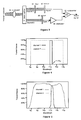
- Figure 3 depicts a block diagram of one embodiment of the infrared spectral difference detector.
- This embodiment is comprised of a collimator 10 which defines a field of view for the detector.
- Infrared radiation in the field of view is split by the beam splitter 11 into two channels.
- filter 21 passes only radiation having wavelengths within a predetermined bandwidth.
- the channel-one sensor 20 provides an output signal which is proportional to the radiation intensity passing through the filter 21.
- unfiltered radiation is passed directly to channel-two sensor 30 which produces a signal proportional to the intensity of the radiation in the second channel.
- the latter signal is normalized by a variable gain signal attenuator 35.
- the gain (or attenuation) of attenuator 35 is adjusted so that the inputs to the signal window comparator 40 are approximately equal when the distribution of infrared radiation in the field of view corresponds to the Planck formula for blackbody radiation.
- the window comparator 40 provides a null (zero) signal for blackbody radiation and a non-zero detect signal for deviations from the Planck formula.
- the size of the window desired for window comparator 40 depends upon the nature of the infrared signal source, the fluctuation characteristics of the transmission path (e.g., the atmosphere), the environmental noise levels, and the false alarm rate desired.
- the window comparator 40 can be a simple signal comparator which provides a detect signal when one input to the comparator is greater than the other and no detect signal otherwise.
- the gain of signal amplifier 35 is adjusted according to the relative pass-band characteristics of the two infrared radiation channels.
- Figure 4 provides an idealized case for discussion purposes, where channel two is sensitive to all radiation within a five micron band from 8 ⁇ to 13 ⁇ , and filter 21 passes only radiation within a 0.25 micron band from 11.0 ⁇ to 11.25 ⁇ . Thus filter 21 passes 5% of the overall wavelength bandwidth of channel two. Filter 21 has, in addition, no degradation of intensity with its passband and a sharp cutoff on each side of its passband. With this configuration, the infrared radiation power in channel one after filtering will be 5% of the power in channel two.
- the gain of attenuator 35 therefore, should be set to 0.05. With this setting the window comparator 40 will, in a system operated in a linear region, provide the appropriate null and detect signals.
- the foregoing normalization technique can be generalized for filters having non-ideal band pass shapes, such as those depicted, for example, in Figure 5.
- the measure of the area under the composite (collimator 10 plus filter 21) transmission curve for channel one is divided by the measure of the area under the transmission curve for channel two, and the quotient so derived is used for the fractional gain of signal attenuator 35.
- the zeroed or non-detect state is set by adjusting the gain for zero difference signal while pointing the detector at a surface which has emissivity near unity throughout the wavelength region of interest and which is controlled to be of the same general temperature as the expected targets.
- the normalization procedure is independent of the position of the channel-one transmission curve with respect to wavelength. Only the magnitude of the transmission area, not its position, is important for proper normalization of the amplifier 35.
- a source having a spectral intensity corresponding to that of blackbody radiation is preferably used for calibration, it will be appreciated that, depending upon the target characteristics, a non-blackbody source may be desired or required for calibration.
- the output of sensor 20 may be insufficient or undesirable for direct provision to window comparator 40. In this case it would be preferable to amplify the output of sensor 20 rather than attenuate the output of sensor 30. Therefore, a variable-gain signal amplifier would be placed in channel one rather than the attenuator in channel two. The normalization gain is then the reciprocal of the gains previously discussed, i.e., the proper gain is numerically equal to the quotient of the area under the channel-two transmission curve divided by the area under the composite channel-one transmission curve. It will also be appreciated that a combination of amplification of the output of sensor 20 (channel one) and attenuation of the output of sensor 30 (channel two) may be used to obtain signal levels most suitable for use with window comparator 40.
- neutral density filter of appropriate strength could replace the signal attenuator 35.
- the neutral density filter would be placed between the beam splitter 11 and the channel-two sensor 30.
- the neutral density filter has the characteristic of passing all wavelengths equally within the range of interest, but at reduced intensity. The reduction in radiation intensity prior to sensing has the same effect as attenuating the signal after sensing.
- the present invention can also be implemented with reflection-type filters, rather than absorption filters.
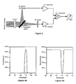
- a particularly advantageous arrangement is to combine the functions of filtering and beam splitting, as depicted in Figure 6.
- Infrared energy impinges on a surface 11 which passes infrared energy in a narrow band as shown in Figure 6A.
- the filter of Figure 6A having peak transmittance of about 90% at 11 ⁇ and a bandwidth of about 0.5 ⁇ at one-half peak transmittance, has been selected to detect a target emitting radiation at 11 ⁇ .
- the remainder of the infrared energy incident on the filter reflects from the surface, as shown in Figure 6B.
- the sharp reflection cut-off points at 8 ⁇ and 13 ⁇ are arbitrary and shown for illustrative purposes only.
- the reflected energy is focused onto sensor 30.
- the transmitted energy is focused onto sensor 20.
- the two channels of information thus created are processed according to the discussion above by amplifying the signal from sensor 20 or attenuating the signal from sensor 30 and providing them to a signal comparator 40.
- the output from the comparator 40 is detected by a meter 50 or other indicating means.
- the filter/beam splitter 11 can be an InfrabandTM narrow band pass filter from Optical Coating Laboratory, Inc., Santa Rosa, California or a Laser Line Interference Filter from Oriel, Stratford, Connecticut.
- filters with differing passband characteristics can be placed in both channels of the detector. With proper normalization, a subtraction of the signals from the sensors in the two channels will give a null output in the presence of blackbody radiation. Furthermore, the presence in the detector field of view of a source or absorber having a wavelength in either of the passbands of the two filters will provide a detect signal of either positive or negative polarity from the subtractor circuit.
- filter A has pass characteristics given by pass curve 60 in Figure 7
- filter B has pass characteristics given by the pass curve 65 in Figure 7.
- the area under the pass curve 60 is equal to the area under curve 65.
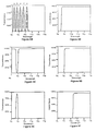
- Figure 8 depicts a six-channel analyzer with five filtered channels and a sixth channel which receives the remaining unfiltered energy incident within the field of view.
- the field of view is defined by a collimator 10 through which infrared radiation passes to impinge on filter/beam splitter 11a. Only energy within the 8.0 ⁇ to 8.5 ⁇ range is transmitted by filter/beam splitter 11a, as is shown in Figure 8A, curve a, after which it is detected by sensor 20a. The remaining energy is reflected, as is shown in Figure 8B.
- the reflected energy next encounters filter/beam splitter 11b which transmits energy within the 8.5 ⁇ to 9.0 ⁇ range, as shown in Figure 8A, curve b.
- the transmitted energy depicted in Figure 8E is detected by sensor 20b, while the remaining energy is reflected according to the reflection characteristic shown in Figure 8C.
- the infrared energy at point 15 has all of the energy with wavelengths above 9.0 ⁇ , as shown in Figure 8D.
- the reflection/transmission process is repeated three more times, by filters 11c, 11d and 11e having transmission characteristics shown in Figure 8A, curves c, d and e. This process provides five separate narrow-band signals at different wavelengths, followed by a "residue" signal provided by the last sensor 20f.
- the signal from this sensor is representative of the remaining energy shown in Figure 8F.
- the number of channels in the multichannel spectrum analyzer is limited only by the width of each filter transmission band as compared to the total bandwidth of the infrared frequencies of interest.
- filter bandwidths of 0.5 ⁇ would permit a multichannel analyzer of eight channels over the wavelength range 8.0 ⁇ to 12.0 ⁇ .
- Narrower band pass filters would allow for correspondingly more channels.
- the multichannel spectrum analyzer provides a number of signals, corresponding to the number of channels, each representative of the intensity of infrared radiation having wavelengths within the passband of the associated filter. These signals may be adjusted, combined or compared algebraically in any manner and sequence which would produce meaningful results for targets of interest. Alternatively, the outputs from all of the sensors may be quantified and displayed in histogram fashion to show spectral intensity density as a function of wavelength. In this manner, the multichannel spectral difference detector would present a direct representation of the variation of infrared radiation as a function of wavelength for the instantaneous field of view of the detector. As an example of the display produced by the alternative treatment of the sensor outputs, Figure 9A depicts the histogram produced by an eight-channel multichannel analyzer when its field of view contains radiation having the spectral distribution shown in Figure 9B.
- a focused or slightly defocused beam of infrared energy illuminates two small infrared sensors simultaneously.
- the sensors are sufficiently small and closely spaced enough that they gather energy emitted by the same object. They thus have essentially the same instantaneous field of view relative to the subtense of the target object.
- a transmission filter 21 is mounted directly over the sensor 20.
- Another transmission filter 31 is optionally mounted directly over sensor 30.
- the channel-one signal from sensor 20 is processed through a variable amplifier/attenuator 25 and passed to the comparator 40, where it is compared with the channel-two signal provided from sensor 30 through variable amplifier/attenuator 35.
- the comparator will provide a detect signal when abnormal amounts of infrared energy pass through filter 21 (or, if present, filter 31).
- the present invention can be simply and inexpensively housed in a "gun" or other aiming device to provide a hand-held unit.
- the hand-held unit can employ a single collimator and a beam splitter or dual collimators defining substantially identical fields of view as depicted in Figure 11.
- Filter 21 is mounted between collimator 10a and the channel-one sensor 20. Provision can be made for interchangeable filters.
- Sensor 30 senses infrared radiation passing through collimator 10b.
- the adjustable gain amplifier 25 is used to normalize the channel-one signal, as discussed above. The signals in the two channels are compared by comparator 40 and a detect signal is passed to the detect indicator 50.
- an on/off switch 12 operatively associated with the gun trigger is switched on.
- Power may be supplied by batteries mounted in the gun handle.
- the amplifier gain is adjusted by an adjustment control 28 operatively connected to the amplifier 25.
- the gun may then be pointed in the desired direction and the detect indicator 50, mounted at the rear of the gun as shown in Figure 11, is checked for a detect indication.
- a subtractor replaces the comparator 40 and the detect indicator 50 is a numeric readout.
- the numeric readout quantifies the magnitude of the difference signal produced by the subtractor, providing an indication of the relative strength of the infrared signal source or absorber as compared to the blackbody reference signal.
- the collimators should preferably provide a fairly narrow field of view so as to give a fairly precise indication of the direction of the infrared source of interest.
- the operator may easily hold and wave the device of Figure 11 around in the general direction of the sources to be investigated for spectral differences.
- the operator receives an immediate and continuous update on the strength of the target spectral differences detected within the narrow field of view. By continuing to point the device in differing directions, he can build a mental picture of the size, shape and location of the target object.
- the device is carried within a platform or turret which allows the device to be pointed throughout the area of interest, and signals representing the pointing angles and the device detection level are fed into a computer, an electronic picture of the objects of interest can be built up.
- the pictorial information may be displayed locally, or communicated to a distant central control station for display.
- the detect indicator 50 may also communicate by audible tones of varying intensity, frequency or pulse rate or by other visual means, such as a meter or lights of varying intensity, color or number.
- the device of Figure 11 may also, of course, be implemented, calibrated, and used with a single collimator and a beam splitter as shown in Figure 3 and Figure 6.
- the use of a single collimator and a conventional beam splitter automatically assures that both detectors are looking at the same target but, because the radiation is split between the two detectors, the radiation intensity provided to each detector is reduced.
- the use of dual collimator provides a higher radiation intensity to each detector but requires that the two collimators be boresighted so that both detectors view essentially the same target area.
- the present invention may also be used in conjunction with a so-called Forward-Looking InfraRed ("FLIR") imager, such as described in U.S. Patent No. 4,328,516, by modifications to the imager, such as those shown in Figure 12.
- FLIR Forward-Looking InfraRed
- a filter/beam splitter 130 is placed in the infrared radiation path between the scanning mirror 112 and the infrared lens 119 (if present) preceding the infrared sensor array 113.
- An infrared lens 139 and array of infrared sensors 133 identical to the array 113 is added and positioned to receive the reflected infrared energy.
- the filter/beam splitter 130 passes only a narrow preselected band of wavelengths, depending upon the choice of the filter/beam splitter 130.
- the passed radiation and the reflected radiation are scanned across the sensor arrays 113 and 133, respectively, by the action of the scanning mirror 112.
- the two arrays of sensors thus produce two multi-signal channels of information.
- the outputs from the existing and added arrays of sensors are amplified by the existing set of amplifiers 114 and a new set of amplifiers 134, respectively, and passed to an added array of signal subtractors 140.
- time delay of the sensor signals in one or the other of the two channels may be necessary, as those skilled in the art will appreciate.
- the outputs from the signal subtractors 140 may then be passed to the LED array 115 where subsequent processing proceeds by means of standard FLIR techniques.
- the modification just described will enable the modified imager to produce images on the CRT display 118 which are medium grey for blackbody radiation, with bright areas indicating sources of infrared radiation of the preselected band of wavelengths and dark areas indicating absorbers of infrared radiation within the preselected wavelength band.
- the outputs from the subtractor array 140 may be used to generate false color images of the kind well-known to those skilled in the art.
- any infrared imager such as unscanned, or staring, arrays of infrared sensors and scanned systems having only a single infrared sensor, such as shown in Figure 13.
- the imager may provide a real time, volatile display or may employ frame-store devices, as those skilled in the art will appreciate.
Landscapes
- Physics & Mathematics (AREA)
- Spectroscopy & Molecular Physics (AREA)
- General Physics & Mathematics (AREA)
- Health & Medical Sciences (AREA)
- Toxicology (AREA)
- Engineering & Computer Science (AREA)
- Multimedia (AREA)
- Signal Processing (AREA)
- Radiation Pyrometers (AREA)
- Transforming Light Signals Into Electric Signals (AREA)
- Photometry And Measurement Of Optical Pulse Characteristics (AREA)
Applications Claiming Priority (4)
| Application Number | Priority Date | Filing Date | Title |
|---|---|---|---|
| US22839488A | 1988-08-04 | 1988-08-04 | |
| US228394 | 1988-08-04 | ||
| US26191388A | 1988-10-24 | 1988-10-24 | |
| US261913 | 1988-10-24 |
Publications (2)
| Publication Number | Publication Date |
|---|---|
| EP0354066A2 true EP0354066A2 (fr) | 1990-02-07 |
| EP0354066A3 EP0354066A3 (fr) | 1990-11-14 |
Family
ID=26922338
Family Applications (2)
| Application Number | Title | Priority Date | Filing Date |
|---|---|---|---|
| EP19890307997 Withdrawn EP0354066A3 (fr) | 1988-08-04 | 1989-08-04 | Détecteur de differénce spectrale dans l'infrarouge |
| EP19890307998 Withdrawn EP0354067A3 (fr) | 1988-08-04 | 1989-08-04 | Détecteur de différence spectrale dans l'infrarouge |
Family Applications After (1)
| Application Number | Title | Priority Date | Filing Date |
|---|---|---|---|
| EP19890307998 Withdrawn EP0354067A3 (fr) | 1988-08-04 | 1989-08-04 | Détecteur de différence spectrale dans l'infrarouge |
Country Status (1)
| Country | Link |
|---|---|
| EP (2) | EP0354066A3 (fr) |
Cited By (8)
| Publication number | Priority date | Publication date | Assignee | Title |
|---|---|---|---|---|
| CH685520A5 (de) * | 1992-01-24 | 1995-07-31 | Lasertape Gmbh | Laufzeitmesser. |
| FR2738630A1 (fr) * | 1995-09-08 | 1997-03-14 | Thomson Csf | Procede de classification de menaces par detection infrarouge bispectrale et dispositif de veille correspondant |
| EP0747680A3 (fr) * | 1995-06-07 | 1998-04-22 | Santa Barbara Research Center | Système spectroscopique différentiel à haute résolution |
| WO2003041585A1 (fr) * | 2001-11-16 | 2003-05-22 | Caijie Yan | Procede medical et appareil d'obtention d'une image infrarouge |
| US9448134B2 (en) | 2014-06-23 | 2016-09-20 | Exxonmobil Upstream Research Company | Systems for detecting a chemical species and use thereof |
| US9501827B2 (en) | 2014-06-23 | 2016-11-22 | Exxonmobil Upstream Research Company | Methods and systems for detecting a chemical species |
| CN108489610A (zh) * | 2018-02-06 | 2018-09-04 | 中国科学院长春光学精密机械与物理研究所 | 基于多通路离焦差异的瞬时成像系统 |
| EP3564635A1 (fr) * | 2015-05-22 | 2019-11-06 | IRnova AB | Détecteur d'imagerie infrarouge |
Families Citing this family (11)
| Publication number | Priority date | Publication date | Assignee | Title |
|---|---|---|---|---|
| FR2665600A1 (fr) * | 1990-08-03 | 1992-02-07 | Thomson Csf | Procede de detection pour camera panoramique, camera pour sa mise en óoeuvre, et systeme de veille equipe d'une telle camera. |
| FR2670980A1 (fr) * | 1990-12-20 | 1992-06-26 | Thomson Csf | Detecteur infrarouge a haute capacite d'identification, et camera thermique comportant un tel detecteur. |
| DE19502521A1 (de) * | 1995-01-27 | 1996-08-01 | Abb Patent Gmbh | Passiv-Infrarot-Melder mit einer Optik, die von einem Strahlungsobjekt emittierte Wärmestrahlung auf einen Infrarotsensor fokussiert |
| US7315667B2 (en) * | 2005-12-22 | 2008-01-01 | Palo Alto Research Center Incorporated | Propagating light to be sensed |
| US9164037B2 (en) | 2007-01-26 | 2015-10-20 | Palo Alto Research Center Incorporated | Method and system for evaluation of signals received from spatially modulated excitation and emission to accurately determine particle positions and distances |
| US8821799B2 (en) | 2007-01-26 | 2014-09-02 | Palo Alto Research Center Incorporated | Method and system implementing spatially modulated excitation or emission for particle characterization with enhanced sensitivity |
| US8629981B2 (en) | 2008-02-01 | 2014-01-14 | Palo Alto Research Center Incorporated | Analyzers with time variation based on color-coded spatial modulation |
| US9029800B2 (en) | 2011-08-09 | 2015-05-12 | Palo Alto Research Center Incorporated | Compact analyzer with spatial modulation and multiple intensity modulated excitation sources |
| US8723140B2 (en) | 2011-08-09 | 2014-05-13 | Palo Alto Research Center Incorporated | Particle analyzer with spatial modulation and long lifetime bioprobes |
| WO2015199912A1 (fr) | 2014-06-23 | 2015-12-30 | Exxonmobil Upstream Research Company | Amélioration de qualité d'image différentielle pour un système à détecteurs multiples |
| CN110617887B (zh) * | 2019-09-26 | 2021-05-18 | 华中科技大学 | 一种目标辐射率测量方法及装置 |
Family Cites Families (7)
| Publication number | Priority date | Publication date | Assignee | Title |
|---|---|---|---|---|
| US3130308A (en) * | 1956-11-19 | 1964-04-21 | Barnes Eng Co | Three detector frequency sharing system for radiometers |
| US4056720A (en) * | 1976-03-08 | 1977-11-01 | Cincinnati Electronics Corporation | Scanning point source optical energy detector |
| US4086616A (en) * | 1976-12-23 | 1978-04-25 | The United States Of America As Represented By The Secretary Of The Navy | All-weather multi-spectral imaging system |
| US4409483A (en) * | 1980-10-07 | 1983-10-11 | Westinghouse Electric Corp. | Radiant energy differential sensor system |
| DE3041670A1 (de) * | 1980-11-05 | 1982-09-09 | Naamloze Vennootschap Philips' Gloeilampenfabrieken, 5621 Eindhoven | Vorrichtung zum detektieren eines warmen punktes in einer landschaftsszene mit hilfe von infrarotstrahlung und mit einer derartigen vorrichtung versehenes lenksystem fuer flugkoerper |
| DE3124716A1 (de) * | 1981-06-24 | 1983-05-19 | Licentia Patent-Verwaltungs-Gmbh, 6000 Frankfurt | "anordnung zur mehrspektralen abbildung von objekten, vorzugsweise von zielen" |
| US4419692A (en) * | 1981-12-31 | 1983-12-06 | Texas Medical Instruments, Inc. | High speed infrared imaging system |
-
1989
- 1989-08-04 EP EP19890307997 patent/EP0354066A3/fr not_active Withdrawn
- 1989-08-04 EP EP19890307998 patent/EP0354067A3/fr not_active Withdrawn
Cited By (11)
| Publication number | Priority date | Publication date | Assignee | Title |
|---|---|---|---|---|
| CH685520A5 (de) * | 1992-01-24 | 1995-07-31 | Lasertape Gmbh | Laufzeitmesser. |
| EP0747680A3 (fr) * | 1995-06-07 | 1998-04-22 | Santa Barbara Research Center | Système spectroscopique différentiel à haute résolution |
| FR2738630A1 (fr) * | 1995-09-08 | 1997-03-14 | Thomson Csf | Procede de classification de menaces par detection infrarouge bispectrale et dispositif de veille correspondant |
| WO2003041585A1 (fr) * | 2001-11-16 | 2003-05-22 | Caijie Yan | Procede medical et appareil d'obtention d'une image infrarouge |
| US9448134B2 (en) | 2014-06-23 | 2016-09-20 | Exxonmobil Upstream Research Company | Systems for detecting a chemical species and use thereof |
| US9501827B2 (en) | 2014-06-23 | 2016-11-22 | Exxonmobil Upstream Research Company | Methods and systems for detecting a chemical species |
| US9760995B2 (en) | 2014-06-23 | 2017-09-12 | Exxonmobil Upstream Research Company | Methods and systems for detecting a chemical species |
| EP3564635A1 (fr) * | 2015-05-22 | 2019-11-06 | IRnova AB | Détecteur d'imagerie infrarouge |
| US10527497B2 (en) | 2015-05-22 | 2020-01-07 | Irnova Ab | Infrared imaging detector |
| US10788372B2 (en) | 2015-05-22 | 2020-09-29 | Irnova Ab | Infrared imaging detector |
| CN108489610A (zh) * | 2018-02-06 | 2018-09-04 | 中国科学院长春光学精密机械与物理研究所 | 基于多通路离焦差异的瞬时成像系统 |
Also Published As
| Publication number | Publication date |
|---|---|
| EP0354066A3 (fr) | 1990-11-14 |
| EP0354067A2 (fr) | 1990-02-07 |
| EP0354067A3 (fr) | 1991-04-10 |
Similar Documents
| Publication | Publication Date | Title |
|---|---|---|
| EP0354066A2 (fr) | Détecteur de differénce spectrale dans l'infrarouge | |
| US5306913A (en) | Method and apparatus for remote optical detection of a gas present in an observed volume | |
| US4725733A (en) | Apparatus and method for remotely detecting the presence of chemical warfare nerve agents in an air-released thermal cloud | |
| US7186978B2 (en) | Compact emissivity and temperature measuring infrared detector | |
| US20040135989A1 (en) | Cloud sensor | |
| JP4217609B2 (ja) | 画像内電磁背景放射除去方法及び装置 | |
| CN110487514A (zh) | 一种共孔径多光谱光电探测系统的光轴平行性校准系统 | |
| US4495416A (en) | Remote sensing instrument | |
| EP0059025B1 (fr) | Système optique pour un spectrophotomètre | |
| GB2325049A (en) | Laser beam angle detection | |
| US5278402A (en) | Real-scene dispersion sensor detecting two wavelengths and determining time delay | |
| US5070239A (en) | Night vision goggle ambient illumination testing | |
| US6114683A (en) | Plant chlorophyll content imager with reference detection signals | |
| US6597457B1 (en) | Calibration of solar reflectance panel | |
| US6222618B1 (en) | Passive ranging to source of known spectral emission | |
| US20190294024A1 (en) | Methods and apparatus for acousto-optic non-uniformity correction and counter-countermeasure mechanisms | |
| US3765779A (en) | Calibration technique and apparatus | |
| US20080180678A1 (en) | Two-detector gas filter correlation radiometry (GFCR) system using two-dimensional array detection of defocused image and detected-signal summation | |
| Tipper et al. | Novel low-cost camera-based continuous wave laser detection | |
| US5369276A (en) | Method and system for real-time wavelength identification for infrared detectors | |
| AU697325B1 (en) | Passive identification and rangefinder apparatus | |
| GB2203010A (en) | Window circuit direction finder | |
| Simard et al. | Range-gated intensified spectrographic imager: an instrument for active hyperspectral imaging | |
| Watkins et al. | Characterizing atmospheric effects on target contrast | |
| CN110926515A (zh) | 一种不同大气能见度下光电传感器等效作用距离折算方法 |
Legal Events
| Date | Code | Title | Description |
|---|---|---|---|
| PUAI | Public reference made under article 153(3) epc to a published international application that has entered the european phase |
Free format text: ORIGINAL CODE: 0009012 |
|
| AK | Designated contracting states |
Kind code of ref document: A2 Designated state(s): BE DE FR GB NL |
|
| PUAL | Search report despatched |
Free format text: ORIGINAL CODE: 0009013 |
|
| AK | Designated contracting states |
Kind code of ref document: A3 Designated state(s): BE DE FR GB NL |
|
| 17P | Request for examination filed |
Effective date: 19910425 |
|
| 17Q | First examination report despatched |
Effective date: 19930910 |
|
| STAA | Information on the status of an ep patent application or granted ep patent |
Free format text: STATUS: THE APPLICATION IS DEEMED TO BE WITHDRAWN |
|
| 18D | Application deemed to be withdrawn |
Effective date: 19940121 |