EP0354157A2 - Ensemble de montage pour moteur électrique - Google Patents
Ensemble de montage pour moteur électrique Download PDFInfo
- Publication number
- EP0354157A2 EP0354157A2 EP89630049A EP89630049A EP0354157A2 EP 0354157 A2 EP0354157 A2 EP 0354157A2 EP 89630049 A EP89630049 A EP 89630049A EP 89630049 A EP89630049 A EP 89630049A EP 0354157 A2 EP0354157 A2 EP 0354157A2
- Authority
- EP
- European Patent Office
- Prior art keywords
- motor
- mounting
- shaft
- ears
- mounting plate
- Prior art date
- Legal status (The legal status is an assumption and is not a legal conclusion. Google has not performed a legal analysis and makes no representation as to the accuracy of the status listed.)
- Granted
Links
Images

Classifications
-
- D—TEXTILES; PAPER
- D06—TREATMENT OF TEXTILES OR THE LIKE; LAUNDERING; FLEXIBLE MATERIALS NOT OTHERWISE PROVIDED FOR
- D06F—LAUNDERING, DRYING, IRONING, PRESSING OR FOLDING TEXTILE ARTICLES
- D06F37/00—Details specific to washing machines covered by groups D06F21/00 - D06F25/00
- D06F37/20—Mountings, e.g. resilient mountings, for the rotary receptacle, motor, tub or casing; Preventing or damping vibrations
- D06F37/206—Mounting of motor
-
- H—ELECTRICITY
- H02—GENERATION; CONVERSION OR DISTRIBUTION OF ELECTRIC POWER
- H02K—DYNAMO-ELECTRIC MACHINES
- H02K5/00—Casings; Enclosures; Supports
- H02K5/26—Means for adjusting casings relative to their supports
-
- F—MECHANICAL ENGINEERING; LIGHTING; HEATING; WEAPONS; BLASTING
- F16—ENGINEERING ELEMENTS AND UNITS; GENERAL MEASURES FOR PRODUCING AND MAINTAINING EFFECTIVE FUNCTIONING OF MACHINES OR INSTALLATIONS; THERMAL INSULATION IN GENERAL
- F16H—GEARING
- F16H7/00—Gearings for conveying rotary motion by endless flexible members
- F16H7/08—Means for varying tension of belts, ropes or chains
- F16H2007/0889—Path of movement of the finally actuated member
- F16H2007/0893—Circular path
Definitions
- This invention relates to a dynamoelectric mounting assembly, and in particular, to a mounting assembly for an electric motor used in washing machine applications. While the invention is described in detail with respect to such applications, those skilled in the art will recognize the wider applicability of the inventive principles disclosed hereafter.
- motors are typically mounted relative to a power transmission assembly which transmits the power supplied by the motor to an agitator within a tub lying above the motor and transmission assembly.
- the transmission also supplies power conveyed by the motor to an interior perforated tub which holds the clothes so that when the perforated tub is spun by the transmission, liquid is removed from the clothes by centrifugal force.
- motor mountings used to position a motor relative to the transmission are typically adaptations for specific applications. If there is a typical motor mounting bracket, one might find that the bracket is symmetrical about the motor and that four mounting bolts are used to secure the motor to the machine support structure.
- a two point motor mounting assembly for attaching an electric motor to a mounting plate relative to a washing machine transmission, also mounted to that plate, is provided, which employs mounting ears extending outwardly from the front endshield of the motor.
- the combination of mounting ears which are an integral part of an endshield of the motor and specifically the front endshield through which the motor shaft extends with a mounting plate configured with an open ended slot like yoke on one end to embrace the motor and an adjoining circular opening to accommodate the rotating shaft of the washing machine transmission, both of which shafts are pointing downwardly, through the mounting plate, provides the mounting arrangement for accomplishing the objects of the present invention.
- the yoke arms which in the preferred embodiment partially encircle the motor, have respective parallel closed ended slots formed in them to position the motor. These slots align with square holes in each of the mounting ears of the front endshield of the motor so that when a bolt is keyed into the square hole in each of the mounting ears, and a threaded end extended into and through the slot in each of the yoke arms, the motor can be moved within the limitations of the yoke arm slots away from the transmission to apply tension to the belt between the pulley on the motor and the pulley on the transmission. Thereafter, when the bolt is then tightened down by means of a washer and nut being placed on its threaded end, the belt tension is set and the motor position is fixed.
- the two bolts, one in each of the mounting ears, are on a line apart from each other but normal to a line between the shaft of the transmission and the shaft of the motor.
- the motor mounting ears are fixed upon the top surface of the mounting plate with the motor supported within the yoke upon the top surface of the mounting plate, with the tension force upon the belt between the two pulleys below the surface of the mounting plate.
- the motor is caused to be pressed against the free end extremities of the yoke arms while simultaneously being fixed to the mounting plate by the bolts.
- the mounting ears are integrally constructed with the front endshield of the motor.
- a stiffener preferably is added to the underside of each of the mounting ears to increase their structural strength. Since the mounting ears are reduced in size dimensionally and the additional set of bolts that would normally be required in a typical installation have been eliminated, the length of the yoke arms of the mounting plate is reduced with with an additional result in savings in material cost.
- the combination of shortened yoke arms for a mounting plate which supports a motor by means of mounting ears which are part of the front motor endshield and which rest upon the top surface of the yoke arms, being secured thereto by means of bolts passing through the mounting ears above and the yoke arms below at two points provide support for the motor upon the mounting plate that securely holds the motor in place.
- a washing machine 10 is shown with an outer washtub 12 and the inner perforated wash tub 14 contained within the outer tub 12.
- the combined washtub 12 and inner perforated tub 14 are filled with water.
- the agitator 16 is churning the water within the two tub combination, water fills both the inner and outer tubs.
- the perforated tub 14 is spun so that the water in the clothes is forced out of them and through the perforations to the outer washtub 12 and then out of the machine in a conventional way.
- a transmission 18 and a mounting plate 20 Underlying the tubs 12 and 14 is a transmission 18 and a mounting plate 20 to which the transmission 18 is attached by means of a plurality of supports 22 which include a plurality of bolts 23 for connecting the plate 20 to the overall washing machine structure.
- a motor 28 Mounted along side the transmission 18 on the mounting plate 20 is a motor 28 which is supported upon the mounting plate 20 by means of a pair of mounting ears 32.
- the ears 32 are attached to the mounting plate 20 through bolts 30 and attached nuts 31. Other means of attachment may be employed, if desired.
- a shaft 42 of the motor having a pulley 44 attached to it is connected by means of a belt 46 to a pulley 26 on a shaft 24 of the transmission 18.
- the motor 28 includes of a front endshield 33, a rear end shield 34, with a rotor assembly 39 and stator assembly 35 lying in between.
- a fan 41 is located within the front endshield 33.
- the shaft or shaft extension 42 of the motor exits the front endshield 33.
- shaft 42 is in a vertical position facing downward, and the pulley 44 is attached to the shaft extension 42 after it exits front endshield 33.
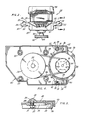
- FIG 4 is the reverse view of Figure 3 which shows that the belt 46 is held in tension between the pulley 44 of the motor 28 and the pulley 26 on the shaft 24 of the transmission 19.
- the mounting ears 32 are pulled against the extremities of the yoke arms 52 of the mounting plate 20 so that the motor 28 is held against the mounting plate by the effect of the belt pulling on the motor pulley 44 under the mounting plate 20 and the bolts 30 passing through the slots 36 in the mounting plate 20 and being secured by the nuts 31.
- the mounting ears 32 preferably have square bolt holes 38 formed in them. The bolt holes 38 are in registration with a part of slots 36 in the yoke arms 52 of the mounting plate 20.
- Figure 5 more clearly shows in cross-section the square hole 38 in the mounting ear 32 and the threaded portion of the bolt 30 passing through the slot 36, a washer 37 and the threaded nut 31 on the underlying side of the mounting plate 20.
- the slot 36 permits the preselected, adjustable movement of motor 28. That is, movement of the ears 32 and the bolts 30 on each side of the motor 28 along the slot 36 permit a user to set the correct tension on belt 46 between the pulley 44 on the motor 28 and the pulley 26 on the transmission 18.
- a stiffener 40 normal to the mounting ears 32 facing downward in the direction of the front endshield 33, as seen in Figure 4, may be provided in the mounting assembly in order to strengthen the mounting ear 32, thereby enabling the ears to withstand the forces being applied upward against the mounting ears 32 by the yoke arms 52 as a result of the forces being applied to the motor 28 by the effect of the belt 46 pulling on the pulley 44 during the operation of motor 28.
- the motor mounting assembly of the present invention is a simple structure and method for mounting a motor to a mounting plate, and to maintain alignment between the motor and a transmission of a working machine.
- the arrangement utilizes only a two point interconnection, enabling the system to use a minimum of material for both the mounting plate supporting the motor and the motor endshield, specifically the mounting ears which are a part of the endshield.
- the system employs only two bolts for mounting the motor, the electric motor is maintained in alignment with the transmission it drives by means of a belt and pulley system. The pulleys are maintained in alignment and a maximum amount of power is thus transmitted through the belt to the pulley on the transmission with a minimum of belt wear.
- the electric motor mounting assembly uses few parts, requires less material, and takes advantage of the structural relationships between the mounting ears on the motor and the yoke arms on the mounting plate to establish a stable relationship between the motor and the mounting plate and maintain a fixed alignment between the pulley on the motor and the pulley on the transmission.
- the fixed relationship of the transmission to the mounting plate and the belt tension between the transmission shaft pulley and the motor shaft pulley beneath the mounting plate act on and cause the side of the mounting ears opposite to the side bolted to the mounting plate to be held secure against the yoke arms at the top of the mounting plate.
- the invention as thus described may be varied to some extent and in some of its aspects by those skilled in the art who have knowledge of the structural dynamics of the present invention and the manner in which the various elements of the present invention can be varied and leveraged without going beyond the scope and spirit of the present invention.
- the physical design or appearance of the motor, or its components may be varied. While the mounting plate was described as having a yoke for supporting the motor, structures other than yokes may be used. The design of the stiffener may be varied or eliminated in other embodiments of this invention. These variations are merely illustrative.
Landscapes
- Engineering & Computer Science (AREA)
- Power Engineering (AREA)
- Textile Engineering (AREA)
- Connection Of Motors, Electrical Generators, Mechanical Devices, And The Like (AREA)
- Motor Or Generator Frames (AREA)
- Lock And Its Accessories (AREA)
- Main Body Construction Of Washing Machines And Laundry Dryers (AREA)
Applications Claiming Priority (2)
| Application Number | Priority Date | Filing Date | Title |
|---|---|---|---|
| US227162 | 1988-08-02 | ||
| US07/227,162 US4922151A (en) | 1988-08-02 | 1988-08-02 | Electric motor mounting assembly |
Publications (3)
| Publication Number | Publication Date |
|---|---|
| EP0354157A2 true EP0354157A2 (fr) | 1990-02-07 |
| EP0354157A3 EP0354157A3 (en) | 1990-11-22 |
| EP0354157B1 EP0354157B1 (fr) | 1994-06-01 |
Family
ID=22852014
Family Applications (1)
| Application Number | Title | Priority Date | Filing Date |
|---|---|---|---|
| EP89630049A Expired - Lifetime EP0354157B1 (fr) | 1988-08-02 | 1989-03-13 | Ensemble de montage pour moteur électrique |
Country Status (13)
| Country | Link |
|---|---|
| US (1) | US4922151A (fr) |
| EP (1) | EP0354157B1 (fr) |
| JP (1) | JP2759337B2 (fr) |
| KR (1) | KR0160494B1 (fr) |
| AU (1) | AU610364B2 (fr) |
| BR (1) | BR8901069A (fr) |
| CA (1) | CA1294660C (fr) |
| DE (1) | DE68915637T2 (fr) |
| DK (1) | DK136589A (fr) |
| ES (1) | ES2055148T3 (fr) |
| MX (1) | MX168119B (fr) |
| NO (1) | NO177476C (fr) |
| NZ (1) | NZ228572A (fr) |
Cited By (2)
| Publication number | Priority date | Publication date | Assignee | Title |
|---|---|---|---|---|
| AU610364B2 (en) * | 1988-08-02 | 1991-05-16 | Emerson Electric Co. | Electric motor mounting assembly |
| WO2006024643A1 (fr) * | 2004-08-31 | 2006-03-09 | BSH Bosch und Siemens Hausgeräte GmbH | Transmission par courroie |
Families Citing this family (18)
| Publication number | Priority date | Publication date | Assignee | Title |
|---|---|---|---|---|
| US5705870A (en) * | 1995-10-19 | 1998-01-06 | Thomsen; Bradley E. | Universally mountable automotive alternator |
| US5902202A (en) * | 1996-12-16 | 1999-05-11 | Maytag Corporation | Belt tensioning system |
| US6098950A (en) * | 1998-02-11 | 2000-08-08 | Zupan; Frank J. | Adjustable accessory mounting system for automobile motor |
| US6935216B1 (en) | 2000-08-02 | 2005-08-30 | Premark Feg L.L.C. | Belt tensioning device |
| US6883959B2 (en) * | 2002-12-23 | 2005-04-26 | Premark Feg L.L.C. | Power bowl lift, motor mount and tensioner for mixing machine |
| US7204774B2 (en) * | 2004-05-17 | 2007-04-17 | Emerson Electric Co. | One-piece drive pulley and belt guide |
| US20070095111A1 (en) * | 2005-10-31 | 2007-05-03 | Watkins Derek L | Belt drive washer |
| DE102005060362A1 (de) * | 2005-12-16 | 2007-06-21 | BSH Bosch und Siemens Hausgeräte GmbH | Befestigungsvorrichtung für einen Motor in einem Haushaltgerät |
| US8278793B2 (en) * | 2009-11-13 | 2012-10-02 | Nidec Motor Corporation | Motor endshield |
| DE102011083652A1 (de) | 2011-09-28 | 2013-03-28 | BSH Bosch und Siemens Hausgeräte GmbH | Anordnung mit einem Laugenbehälter einer Waschmaschine und einem Antriebsmotor sowie Waschmaschine |
| CN103286328B (zh) * | 2013-05-09 | 2016-01-27 | 沈阳第一机床厂 | 双主轴的卧式数控车床 |
| KR102091546B1 (ko) * | 2013-06-21 | 2020-03-23 | 삼성전자주식회사 | 세탁기 |
| CN104485181A (zh) * | 2014-12-19 | 2015-04-01 | 无锡市士民机械设备厂 | 成圈包膜一体机的驱动电机安装结构 |
| DE102015217216A1 (de) * | 2015-09-09 | 2017-03-09 | Frankl & Kirchner GmbH & Co KG Fabrik für Elektromotoren u. elektrische Apparate | Anbau-Antriebsmotor-Baugruppe für eine Nähmaschine |
| US20170098987A1 (en) * | 2015-10-06 | 2017-04-06 | Hamilton Sundstrand Corporation | Line start permanent magnet brushless motor |
| AU2016247118B2 (en) * | 2015-10-19 | 2020-08-06 | Fna Group, Inc. | Mounting alignment system |
| CN109434745A (zh) * | 2018-11-03 | 2019-03-08 | 邢二江 | 一种驱动电机拆装机构 |
| US12341402B2 (en) * | 2022-01-20 | 2025-06-24 | Schaeffler Technologies AG & Co. KG | Emotor rotor centering and shipping aid with annular disk and bolt holes |
Family Cites Families (10)
| Publication number | Priority date | Publication date | Assignee | Title |
|---|---|---|---|---|
| FR1282851A (fr) * | 1961-02-18 | 1962-01-27 | Borg Warner | Ensemble de transmission d'entraînement, notamment pour machine à laver |
| NL6400410A (fr) * | 1963-01-30 | 1964-07-31 | ||
| JPS53947Y2 (fr) * | 1972-07-18 | 1978-01-12 | ||
| US3848437A (en) * | 1973-02-23 | 1974-11-19 | Maytag Co | Precleaning a token-actuated laundry washing machine |
| US4260125A (en) * | 1979-06-20 | 1981-04-07 | Fred Levine | Brackets for mounting motors |
| JPS6346077Y2 (fr) * | 1980-06-05 | 1988-11-30 | ||
| EP0057294B1 (fr) * | 1981-01-29 | 1985-01-30 | BBC Aktiengesellschaft Brown, Boveri & Cie. | Dispositif de support pour paliers de machines électriques |
| DE3132211A1 (de) * | 1981-08-14 | 1983-03-03 | Licentia Patent-Verwaltungs-Gmbh, 6000 Frankfurt | "trommelwaschmaschine" |
| US4602176A (en) * | 1984-08-30 | 1986-07-22 | Emerson Electric Co. | Means for and method of reducing vibration of noise between a dynamoelectric machine and its application |
| US4922151A (en) * | 1988-08-02 | 1990-05-01 | Emerson Electric Co. | Electric motor mounting assembly |
-
1988
- 1988-08-02 US US07/227,162 patent/US4922151A/en not_active Expired - Lifetime
-
1989
- 1989-02-09 CA CA000590593A patent/CA1294660C/fr not_active Expired - Lifetime
- 1989-03-07 BR BR898901069A patent/BR8901069A/pt not_active IP Right Cessation
- 1989-03-07 NO NO890956A patent/NO177476C/no unknown
- 1989-03-13 DE DE68915637T patent/DE68915637T2/de not_active Expired - Fee Related
- 1989-03-13 ES ES89630049T patent/ES2055148T3/es not_active Expired - Lifetime
- 1989-03-13 EP EP89630049A patent/EP0354157B1/fr not_active Expired - Lifetime
- 1989-03-21 DK DK136589A patent/DK136589A/da not_active Application Discontinuation
- 1989-03-21 KR KR1019890003516A patent/KR0160494B1/ko not_active Expired - Fee Related
- 1989-03-27 MX MX015406A patent/MX168119B/es unknown
- 1989-03-28 AU AU31730/89A patent/AU610364B2/en not_active Ceased
- 1989-03-31 JP JP1083884A patent/JP2759337B2/ja not_active Expired - Fee Related
- 1989-03-31 NZ NZ228572A patent/NZ228572A/en unknown
Cited By (2)
| Publication number | Priority date | Publication date | Assignee | Title |
|---|---|---|---|---|
| AU610364B2 (en) * | 1988-08-02 | 1991-05-16 | Emerson Electric Co. | Electric motor mounting assembly |
| WO2006024643A1 (fr) * | 2004-08-31 | 2006-03-09 | BSH Bosch und Siemens Hausgeräte GmbH | Transmission par courroie |
Also Published As
| Publication number | Publication date |
|---|---|
| DE68915637T2 (de) | 1994-09-22 |
| US4922151A (en) | 1990-05-01 |
| EP0354157B1 (fr) | 1994-06-01 |
| EP0354157A3 (en) | 1990-11-22 |
| CA1294660C (fr) | 1992-01-21 |
| NZ228572A (en) | 1991-04-26 |
| NO890956D0 (no) | 1989-03-07 |
| KR900003470A (ko) | 1990-03-26 |
| NO177476C (no) | 1995-09-20 |
| NO890956L (no) | 1990-02-05 |
| DK136589A (da) | 1990-02-03 |
| JPH0246146A (ja) | 1990-02-15 |
| MX168119B (es) | 1993-05-04 |
| ES2055148T3 (es) | 1994-08-16 |
| KR0160494B1 (ko) | 1998-12-15 |
| NO177476B (no) | 1995-06-12 |
| DE68915637D1 (de) | 1994-07-07 |
| BR8901069A (pt) | 1990-08-28 |
| DK136589D0 (da) | 1989-03-21 |
| JP2759337B2 (ja) | 1998-05-28 |
| AU3173089A (en) | 1990-02-08 |
| AU610364B2 (en) | 1991-05-16 |
Similar Documents
| Publication | Publication Date | Title |
|---|---|---|
| CA1294660C (fr) | Support de montage de moteur electrique | |
| AU643162B2 (en) | Gearless direct drive switched reluctance motor for laundry application | |
| US4819460A (en) | Washing machine with direct drive system | |
| US20090064726A1 (en) | Driving apparatus for washing machine | |
| KR100211866B1 (ko) | 세탁기의 저수조 현가장치 | |
| EP0354158B1 (fr) | Ensemble de moteur à hauteur minimale, utilisant des flasques d'extrémité en aluminium | |
| EP3739105A1 (fr) | Dispositif d'entraînement pour une machine à laver | |
| US3270222A (en) | Vibration and noise isolation support and drive | |
| KR100214260B1 (ko) | 전자동 세탁기의 회전축 지지장치 | |
| RU2006133132A (ru) | Стиральная машина барабанного типа (варианты) и способ сборки узла вала (варианты) | |
| GB2104110A (en) | Drum-type washing machine | |
| KR100565483B1 (ko) | 세탁기 아우터 로터형 모터 | |
| KR100238825B1 (ko) | 세탁기의 구동축 결합구조 | |
| KR0118964Y1 (ko) | 세탁기의 모터취부장치 | |
| CN216250513U (zh) | 一种方便拆装的墙壁开关 | |
| CN219107184U (zh) | 一种便于安装的电机 | |
| CN221242568U (zh) | 一种煮汤机的搅拌传动装置 | |
| EP1707660A1 (fr) | Lave-linge amélioré et appareil ménager semblable avec un tambour | |
| KR200182889Y1 (ko) | 세탁기의 모터 고정장치 | |
| CN222654964U (zh) | 定子固定机构及定子绕线机 | |
| CN219787068U (zh) | 一种球罐焊接监测装置 | |
| KR200232032Y1 (ko) | 세탁기 | |
| CN222674010U (zh) | 一种洗衣机风干机电机的具有调心功能的滚动轴承支架组件 | |
| KR100379467B1 (ko) | 직결식 세탁기 | |
| CN116961304A (zh) | 衣物处理装置 |
Legal Events
| Date | Code | Title | Description |
|---|---|---|---|
| PUAI | Public reference made under article 153(3) epc to a published international application that has entered the european phase |
Free format text: ORIGINAL CODE: 0009012 |
|
| AK | Designated contracting states |
Kind code of ref document: A2 Designated state(s): BE DE ES FR GB IT NL SE |
|
| PUAL | Search report despatched |
Free format text: ORIGINAL CODE: 0009013 |
|
| AK | Designated contracting states |
Kind code of ref document: A3 Designated state(s): BE DE ES FR GB IT NL SE |
|
| 17P | Request for examination filed |
Effective date: 19910516 |
|
| 17Q | First examination report despatched |
Effective date: 19921202 |
|
| GRAA | (expected) grant |
Free format text: ORIGINAL CODE: 0009210 |
|
| AK | Designated contracting states |
Kind code of ref document: B1 Designated state(s): BE DE ES FR GB IT NL SE |
|
| ET | Fr: translation filed | ||
| REF | Corresponds to: |
Ref document number: 68915637 Country of ref document: DE Date of ref document: 19940707 |
|
| REG | Reference to a national code |
Ref country code: ES Ref legal event code: FG2A Ref document number: 2055148 Country of ref document: ES Kind code of ref document: T3 |
|
| ITF | It: translation for a ep patent filed | ||
| EAL | Se: european patent in force in sweden |
Ref document number: 89630049.8 |
|
| PLBE | No opposition filed within time limit |
Free format text: ORIGINAL CODE: 0009261 |
|
| STAA | Information on the status of an ep patent application or granted ep patent |
Free format text: STATUS: NO OPPOSITION FILED WITHIN TIME LIMIT |
|
| 26N | No opposition filed | ||
| PGFP | Annual fee paid to national office [announced via postgrant information from national office to epo] |
Ref country code: FR Payment date: 19990208 Year of fee payment: 11 |
|
| PGFP | Annual fee paid to national office [announced via postgrant information from national office to epo] |
Ref country code: SE Payment date: 19990216 Year of fee payment: 11 Ref country code: GB Payment date: 19990216 Year of fee payment: 11 |
|
| PGFP | Annual fee paid to national office [announced via postgrant information from national office to epo] |
Ref country code: NL Payment date: 19990224 Year of fee payment: 11 |
|
| PGFP | Annual fee paid to national office [announced via postgrant information from national office to epo] |
Ref country code: DE Payment date: 19990226 Year of fee payment: 11 |
|
| PGFP | Annual fee paid to national office [announced via postgrant information from national office to epo] |
Ref country code: BE Payment date: 19990302 Year of fee payment: 11 |
|
| PGFP | Annual fee paid to national office [announced via postgrant information from national office to epo] |
Ref country code: ES Payment date: 19990311 Year of fee payment: 11 |
|
| PG25 | Lapsed in a contracting state [announced via postgrant information from national office to epo] |
Ref country code: GB Free format text: LAPSE BECAUSE OF NON-PAYMENT OF DUE FEES Effective date: 20000313 |
|
| PG25 | Lapsed in a contracting state [announced via postgrant information from national office to epo] |
Ref country code: SE Free format text: LAPSE BECAUSE OF NON-PAYMENT OF DUE FEES Effective date: 20000314 Ref country code: ES Free format text: LAPSE BECAUSE OF NON-PAYMENT OF DUE FEES Effective date: 20000314 |
|
| PG25 | Lapsed in a contracting state [announced via postgrant information from national office to epo] |
Ref country code: BE Free format text: LAPSE BECAUSE OF NON-PAYMENT OF DUE FEES Effective date: 20000331 |
|
| BERE | Be: lapsed |
Owner name: EMERSON ELECTRIC CO. Effective date: 20000331 |
|
| PG25 | Lapsed in a contracting state [announced via postgrant information from national office to epo] |
Ref country code: NL Free format text: LAPSE BECAUSE OF NON-PAYMENT OF DUE FEES Effective date: 20001001 |
|
| GBPC | Gb: european patent ceased through non-payment of renewal fee |
Effective date: 20000313 |
|
| EUG | Se: european patent has lapsed |
Ref document number: 89630049.8 |
|
| PG25 | Lapsed in a contracting state [announced via postgrant information from national office to epo] |
Ref country code: FR Free format text: LAPSE BECAUSE OF NON-PAYMENT OF DUE FEES Effective date: 20001130 |
|
| NLV4 | Nl: lapsed or anulled due to non-payment of the annual fee |
Effective date: 20001001 |
|
| REG | Reference to a national code |
Ref country code: FR Ref legal event code: ST |
|
| PG25 | Lapsed in a contracting state [announced via postgrant information from national office to epo] |
Ref country code: DE Free format text: LAPSE BECAUSE OF NON-PAYMENT OF DUE FEES Effective date: 20010103 |
|
| REG | Reference to a national code |
Ref country code: ES Ref legal event code: FD2A Effective date: 20011010 |
|
| PG25 | Lapsed in a contracting state [announced via postgrant information from national office to epo] |
Ref country code: IT Free format text: LAPSE BECAUSE OF NON-PAYMENT OF DUE FEES;WARNING: LAPSES OF ITALIAN PATENTS WITH EFFECTIVE DATE BEFORE 2007 MAY HAVE OCCURRED AT ANY TIME BEFORE 2007. THE CORRECT EFFECTIVE DATE MAY BE DIFFERENT FROM THE ONE RECORDED. Effective date: 20050313 |