EP0354422A1 - Turbine à gaz avec espace de palier à côté du compresseur - Google Patents
Turbine à gaz avec espace de palier à côté du compresseur Download PDFInfo
- Publication number
- EP0354422A1 EP0354422A1 EP89113942A EP89113942A EP0354422A1 EP 0354422 A1 EP0354422 A1 EP 0354422A1 EP 89113942 A EP89113942 A EP 89113942A EP 89113942 A EP89113942 A EP 89113942A EP 0354422 A1 EP0354422 A1 EP 0354422A1
- Authority
- EP
- European Patent Office
- Prior art keywords
- flow
- gas turbine
- compressor
- turbine according
- sealing air
- Prior art date
- Legal status (The legal status is an assumption and is not a legal conclusion. Google has not performed a legal analysis and makes no representation as to the accuracy of the status listed.)
- Granted
Links
- 238000007789 sealing Methods 0.000 claims description 42
- 238000011144 upstream manufacturing Methods 0.000 claims description 2
- 238000010276 construction Methods 0.000 abstract description 2
- 239000003595 mist Substances 0.000 description 9
- 238000010586 diagram Methods 0.000 description 2
- 238000010926 purge Methods 0.000 description 2
- 230000002411 adverse Effects 0.000 description 1
- 238000002485 combustion reaction Methods 0.000 description 1
- 230000007423 decrease Effects 0.000 description 1
- 230000000694 effects Effects 0.000 description 1
- 238000004519 manufacturing process Methods 0.000 description 1
- 238000009420 retrofitting Methods 0.000 description 1
- 230000003068 static effect Effects 0.000 description 1
- 238000004804 winding Methods 0.000 description 1
Images

Classifications
-
- F—MECHANICAL ENGINEERING; LIGHTING; HEATING; WEAPONS; BLASTING
- F01—MACHINES OR ENGINES IN GENERAL; ENGINE PLANTS IN GENERAL; STEAM ENGINES
- F01D—NON-POSITIVE DISPLACEMENT MACHINES OR ENGINES, e.g. STEAM TURBINES
- F01D25/00—Component parts, details, or accessories, not provided for in, or of interest apart from, other groups
- F01D25/08—Cooling; Heating; Heat-insulation
- F01D25/12—Cooling
- F01D25/125—Cooling of bearings
-
- F—MECHANICAL ENGINEERING; LIGHTING; HEATING; WEAPONS; BLASTING
- F01—MACHINES OR ENGINES IN GENERAL; ENGINE PLANTS IN GENERAL; STEAM ENGINES
- F01D—NON-POSITIVE DISPLACEMENT MACHINES OR ENGINES, e.g. STEAM TURBINES
- F01D11/00—Preventing or minimising internal leakage of working-fluid, e.g. between stages
- F01D11/02—Preventing or minimising internal leakage of working-fluid, e.g. between stages by non-contact sealings, e.g. of labyrinth type
- F01D11/04—Preventing or minimising internal leakage of working-fluid, e.g. between stages by non-contact sealings, e.g. of labyrinth type using sealing fluid, e.g. steam
- F01D11/06—Control thereof
-
- Y—GENERAL TAGGING OF NEW TECHNOLOGICAL DEVELOPMENTS; GENERAL TAGGING OF CROSS-SECTIONAL TECHNOLOGIES SPANNING OVER SEVERAL SECTIONS OF THE IPC; TECHNICAL SUBJECTS COVERED BY FORMER USPC CROSS-REFERENCE ART COLLECTIONS [XRACs] AND DIGESTS
- Y02—TECHNOLOGIES OR APPLICATIONS FOR MITIGATION OR ADAPTATION AGAINST CLIMATE CHANGE
- Y02T—CLIMATE CHANGE MITIGATION TECHNOLOGIES RELATED TO TRANSPORTATION
- Y02T50/00—Aeronautics or air transport
- Y02T50/60—Efficient propulsion technologies, e.g. for aircraft
Definitions
- the invention relates to a gas turbine with a compressor-side bearing chamber for the compressor-side bearing of a first and a second shaft, each of which is connected to a multi-stage compressor and a turbine, and a turbine-side bearing chamber for the turbine-side bearing of both shafts, in which the compressor-side bearing chamber is separated from one Low-pressure compressor-operated sealing air chamber is surrounded, the turbine-side bearing chamber is surrounded by a sealing air chamber which is acted upon by a high-pressure compressor by means of a sealing air line and both bearing chambers are connected in terms of flow via an intermediate shaft space between the first and second shaft.
- the shafts are usually supported on the turbine side by means of ball or roller bearings.
- the bearings are connected by means of a common cavity, the bearing chamber. Since the bearings are lubricated with oil, there is a risk that the resulting oil mist through the gaps between the rotating and fixed door Binary parts escape and get into the flow channel. In addition to increased oil loss and pollution, oil fires can occur on hot turbine parts. For this reason, a sealing air chamber is designed around the storage chamber, which is pressurized with compressed air of higher static pressure than that in the storage chamber. This prevents oil mist from escaping from the storage chamber. The sealing air chamber is supplied with compressed air from the high pressure compressor.
- the compressor-side mounting of the shafts is carried out radially inside the compressor.
- two compressor-side bearing chambers are usually provided, one for the storage of the low-pressure shaft, one for the medium and high-pressure compressor shaft.
- the compressor-side sealing air chamber is fed by the low-pressure compressor or, in the case of a 3-shaft version, by the medium-pressure compressor.
- the object of the invention is to reliably prevent the breakout of intermediate shaft fires in any flight conditions in a gas turbine of the generic type, at the same time preventing the escape of oil mist into the main gas duct.
- the invention has the advantage that the pressure of the rear sealing air chamber can be adjusted depending on the flight condition, as a result of which the necessary ISF is guaranteed while at the same time maintaining a sufficient compressor-side pressure difference between sealing air chamber and storage chamber.
- the pressure in the high-pressure compressor rises because of the increased dynamic pressure, so that the pressure of the turbine-side sealing air chamber and storage chamber also rises via the sealing air line. This leads to an increased ISF and, due to the inflowing oil mist, to an increased compressor chamber pressure. If the sealing air chamber pressure on the compressor side is only slightly controlled, the pressure difference on the compressor side decreases, which entails the risk that oil mist escapes from the compressor side storage chamber and enters the flow channel. When flying slowly at high altitude, however, a Mach number shift occurs in the engine due to the low back pressure, which further adversely reduces the pressure ratio at the compressor-side sealing air chamber, which means that oil mist escapes from the compressor-side bearing chamber and enters the flow channel.
- the arrangement according to the invention then, controlled by flight parameters, lowers the pressure of the turbine-side sealing air chamber, which in turn improves the compressor-side pressure difference is serbar. It is therefore possible to achieve an ISF that is optimal in the entire characteristic field while maintaining a sufficiently large compressor-side pressure difference.
- the flow control valve is controlled by means of the engine inlet pressure or the engine inlet temperature or the ambient temperature or the ambient pressure or the movement speed or the movement height or a combination thereof.
- the valve can be moved by electronic, electrical or pneumatic force.
- the control can take place via the electronic engine control (map control). By measuring one or more of these parameters, an exact determination of the necessary ISF can advantageously be determined.
- Another embodiment of the invention provides that the flow control valve can be controlled by means of the gas temperature in the sealing air line. This enables a particularly simple design of the flow control valve without the need to lay lines from distant measuring sensors.
- the flow control valve is preferably a slide valve.
- the gas temperature is preferably measured using a bimetal sensor.
- a structurally particularly simple flow control valve is possible in connection with a crescent-shaped slide which forms a slide valve and is moved by a bimetallic helix.
- the flow control valve has the following control characteristic: in a lower temperature range rich T1 an average flow value V ⁇ 1 of the volume flow is set. In a medium temperature range T2 a low flow value V ⁇ 2 is set and in a high temperature range T3 a high flow value V ⁇ 3 is set. This control characteristic ensures that the turbine-side sealing air pressure and thus the ISF and the compressor-side pressure difference are optimized over the entire operating range of the engine.
- a preferred embodiment of the flow control valve has a tube section with an 8-shaped cross section, which consists of a flow channel which is adapted to the flow cross section of the sealing air line and is open at both ends and a parallel control tube which is connected to it and is closed at both ends.
- a bimetallic helix is provided and fixed at one end inside the head tube, which is attached to a slide at the other end, the slide being insertable transversely into the flow channel.
- an axial, rotatably mounted holding pin is provided radially inside the bimetal helix, the slide-side end of the bimetal helix being attached to the slide and the other end being connected to the holding pin.
- the axial, rotatably mounted holding pin can also be used to calibrate the system and thus to compensate for manufacturing tolerances of the bimetal helix, since an opening / closing angle associated with a defined temperature can be precisely adjusted.
- the slide is sickle-shaped, and in the V Stellung3 position there is a concave edge just outside the flow channel, in the V ⁇ 2 position completely in the flow channel and in the V ⁇ 1 position with the concave edge partially in the flow channel.
- the desired control characteristic of the flow control valve is achieved in a simple manner, the associated values V ⁇ 1, V ⁇ 2 and V ⁇ 3 can be achieved by changing the geometric dimensions of the slide.
- a preferred development of the invention provides that a flow control valve is provided in a valve line of one or more storage chambers.
- This has the advantage that the pressure differences can be optimized as a function of the above-mentioned control parameters for all the bearing chambers located in the engine, so that there is no risk of oil fire and / or oil mist leakage.
- the entire system in the operating area can be kept at tight pressure differences, as a result of which as much (sealing) air is no longer extracted from the cycle and the effectiveness (performance) increases.
- the gas turbine is designed with three shafts, a third shaft being concentric within the is arranged first and second shaft and is supported on the turbine side together with these in the turbine-side bearing chamber.
- the third shaft is supported in a separate storage chamber on the compressor side.
- a compressor-side bearing chamber two are to be provided, the low-pressure shaft being supported at two bearing points in a front compressor bearing chamber.
- a rear compressor storage chamber is used to support the medium and high pressure shaft on the compressor side.
- the flow control valve according to the invention is then installed in the sealing air line, which leads from the high pressure compressor to the sealing air chamber of the turbine-side bearing chamber. In this case, the control of the sealing air flow mainly influences the flow in the intermediate shaft space between the medium-pressure turbine shaft and the high-pressure turbine shaft.
- An advantageous development of the invention provides that the signal processing for the flow control valve takes place in an engine control unit (MECU, DECU, FADEC).
- the control signals are implemented in a map control.
- the valve can be controlled by an electric motor, electrically or pneumatically.
- Another advantageous embodiment of the invention provides that fixed flow orifices are connected upstream and / or downstream of the flow control valve. A system pre-adjustment can thereby advantageously be achieved.
- the flow control valve is designed as a bypass valve and controls an air flow that is only up to 50% of a main flow.
- the flow control valve could advantageously be made smaller and lighter, or in the event of a failure the functionality of the engine would be maintained.
- the flow control valve can also effect a purge air blow-off instead of the purge air restriction. H. the air is blown into the atmosphere or the bypass duct of the engine.
- the gas turbine 1 shown in axial section in FIG. 1 essentially consists of a low-pressure compressor 16, which is coupled to a low-pressure turbine 18 via a low-pressure turbine shaft 17.
- the low-pressure turbine shaft 17 is mounted in bearing brackets 21 and 22 via a compressor-side bearing 19a and a turbine-side bearing 20b.
- the bearing supports 21 and 22 are fixed in the gas turbine housing 25 by means of support ribs 23 and 24.
- a high-pressure compressor 3 is arranged axially behind the low-pressure compressor 16 and is coupled to a high-pressure turbine 27 via a high-pressure turbine shaft 26.
- the high-pressure turbine shaft 26 is supported in the bearing brackets 21 and 22 via a compressor-side bearing 19b and a turbine-side bearing 20a.
- a sealing air line 29 is branched off from the low pressure compressor 16, which is guided through the compressor-side support rib 23 and acts on a compressor-side sealing air chamber 30.
- a compressor-side bearing chamber 31 is provided radially inside the compressor-side sealing air chamber 30, in which the bearings 19a and 19b are arranged.
- a sealing air line 2 branches off from the high pressure compressor 3 and acts on a turbine-side sealing air chamber 32 via the flow control valve 5 and a turbine-side support rib 24.
- a turbine-side bearing chamber 33 in which the bearings 20a and 20b are located, is provided within the turbine-side sealing air chamber 32.
- An annular intermediate shaft space 34 is arranged between the low-pressure turbine shaft 17 and the high-pressure turbine shaft 26 and communicates with the turbine-side bearing chamber 33 and the compressor-side bearing chamber 31.
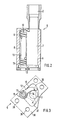
- the flow control valve 5 is shown in section, which is arranged in the sealing air line 2 according to FIG. 1.
- This consists of a tubular section 6 shaped in cross section 8, one part of which is the flow channel 7, which is axially connected to the sealing air line 2.
- the other part of the tube section 6 consists of a control tube 8 which is closed on both sides and in which a bimetallic helix 9 which is wound on an axially arranged holding pin 13 is attached.
- the bimetallic helix 9 is fixed at one end to the holding pin 13 and at the other end to the slide 12.
- Fig. 3 the flow control valve 5 is shown in cross section.
- the sickle-like slide 12 fastened to the holding pin 13 is guided in a circular sector-like recess 35 in the valve housing 36, so that it can be inserted into the flow chamber 7.
- the maximum possible flow channel is released, which is the Position V3 of the flow diagram attached as Fig. 4 corresponds.
- part of the flow channel 7 is covered by the concave edge 15 of the slide 12, so that the flow channel is partially narrowed in accordance with the position V 1.
- the holes 38 serve to fix and mount the flow control valve 5.
- a control diagram for controlling the flow control valve 5 is shown schematically in FIG. 4.
- the flow through the flow control valve 5 or the sealing air line 2 is plotted as an ordinate, while the temperature T of the sealing air is plotted to the right as the abscissa.
- a medium flow value V ⁇ 1 is set, in a medium temperature range ⁇ T2 a low flow value V ⁇ 2 and a high temperature range ⁇ T3 is assigned a high flow value V ⁇ 3.
- the temperature range ⁇ T1 corresponds to the position of the slide 37 (V ⁇ 1) shown in broken lines in FIG. 3, while the flow value V ⁇ 3 corresponds to the position of the slide 12 shown in FIG. 3.
- the slide 12 In the V ⁇ 2 position, the slide 12 is inserted into the flow channel 7 such that both its concave edge 14 and its convex edge 15 lie within the flow channel 7.
Landscapes
- Engineering & Computer Science (AREA)
- Mechanical Engineering (AREA)
- General Engineering & Computer Science (AREA)
- Supercharger (AREA)
- Structures Of Non-Positive Displacement Pumps (AREA)
Applications Claiming Priority (2)
| Application Number | Priority Date | Filing Date | Title |
|---|---|---|---|
| DE3826217A DE3826217A1 (de) | 1988-08-02 | 1988-08-02 | Gasturbine mit einer verdichterseitigen lagerkammer |
| DE3826217 | 1988-08-02 |
Publications (2)
| Publication Number | Publication Date |
|---|---|
| EP0354422A1 true EP0354422A1 (fr) | 1990-02-14 |
| EP0354422B1 EP0354422B1 (fr) | 1992-06-03 |
Family
ID=6360080
Family Applications (1)
| Application Number | Title | Priority Date | Filing Date |
|---|---|---|---|
| EP89113942A Expired - Lifetime EP0354422B1 (fr) | 1988-08-02 | 1989-07-28 | Turbine à gaz avec espace de palier à côté du compresseur |
Country Status (3)
| Country | Link |
|---|---|
| EP (1) | EP0354422B1 (fr) |
| DE (2) | DE3826217A1 (fr) |
| ES (1) | ES2032633T3 (fr) |
Cited By (6)
| Publication number | Priority date | Publication date | Assignee | Title |
|---|---|---|---|---|
| FR2698406A1 (fr) * | 1992-11-25 | 1994-05-27 | Snecma | Procédé de pressurisation d'enceintes lubrifiées d'une turbomachine. |
| WO1994023184A1 (fr) * | 1993-04-01 | 1994-10-13 | Bmw Rolls-Royce Gmbh | Systeme propulseur a turbines a gaz comportant des chambres de paliers et des chambres d'air de barrage |
| EP2824289A1 (fr) * | 2013-07-10 | 2015-01-14 | Rolls-Royce Deutschland Ltd & Co KG | Dispositif et procédé d'évacuation d'air de barrage dans un turboréacteur à double flux et turboréacteur à double flux associé |
| RU2699870C1 (ru) * | 2018-08-03 | 2019-09-11 | Публичное акционерное общество "ОДК-Уфимское моторостроительное производственное объединение" (ПАО "ОДК-УМПО") | Охлаждаемая турбина двухконтурного газотурбинного двигателя |
| RU2700110C1 (ru) * | 2018-11-07 | 2019-09-12 | Публичное акционерное общество "ОДК-Уфимское моторостроительное производственное объединение" (ПАО "ОДК-УМПО") | Двухконтурный газотурбинный двигатель |
| EP3929407A1 (fr) * | 2020-06-23 | 2021-12-29 | ABB Schweiz AG | Bague de tuyère modulaire pour une étage de turbine d'une turbomachine |
Families Citing this family (2)
| Publication number | Priority date | Publication date | Assignee | Title |
|---|---|---|---|---|
| DE19956919A1 (de) * | 1999-11-26 | 2001-05-31 | Rolls Royce Deutschland | Gasturbinen-Triebwerk mit einer Lagerkammer |
| EP2383440A1 (fr) | 2010-04-28 | 2011-11-02 | Siemens Aktiengesellschaft | Turbine incluant un système d'étanchéité à air avec clapet |
Citations (6)
| Publication number | Priority date | Publication date | Assignee | Title |
|---|---|---|---|---|
| US2603420A (en) * | 1948-10-07 | 1952-07-15 | Tacchi Percy George | Thermostatically controlled mixing valve |
| GB702931A (en) * | 1951-04-18 | 1954-01-27 | Bristol Aeroplane Co Ltd | Improvements in or relating to rotary machines comprising fluid compressing means |
| FR2278024A1 (fr) * | 1974-07-08 | 1976-02-06 | Gen Electric | Valve de reglage pour fluides |
| GB2111607A (en) * | 1981-12-08 | 1983-07-06 | Rolls Royce | Bearing chamber pressurisation system for a machine |
| GB2119858A (en) * | 1982-05-13 | 1983-11-23 | United Technologies Corp | Means for controlling air scavenge pressure in the bearing compartment of gas turbines |
| EP0128850A2 (fr) * | 1983-05-31 | 1984-12-19 | United Technologies Corporation | Système d'équilibrage et de refroidissement |
Family Cites Families (2)
| Publication number | Priority date | Publication date | Assignee | Title |
|---|---|---|---|---|
| GB1301282A (fr) * | 1969-07-15 | 1972-12-29 | ||
| US4433539A (en) * | 1982-05-13 | 1984-02-28 | United Technologies Corporation | Means for controlling air scavenge pressure in the bearing compartment of gas turbines |
-
1988
- 1988-08-02 DE DE3826217A patent/DE3826217A1/de not_active Withdrawn
-
1989
- 1989-07-28 ES ES198989113942T patent/ES2032633T3/es not_active Expired - Lifetime
- 1989-07-28 DE DE8989113942T patent/DE58901578D1/de not_active Expired - Lifetime
- 1989-07-28 EP EP89113942A patent/EP0354422B1/fr not_active Expired - Lifetime
Patent Citations (6)
| Publication number | Priority date | Publication date | Assignee | Title |
|---|---|---|---|---|
| US2603420A (en) * | 1948-10-07 | 1952-07-15 | Tacchi Percy George | Thermostatically controlled mixing valve |
| GB702931A (en) * | 1951-04-18 | 1954-01-27 | Bristol Aeroplane Co Ltd | Improvements in or relating to rotary machines comprising fluid compressing means |
| FR2278024A1 (fr) * | 1974-07-08 | 1976-02-06 | Gen Electric | Valve de reglage pour fluides |
| GB2111607A (en) * | 1981-12-08 | 1983-07-06 | Rolls Royce | Bearing chamber pressurisation system for a machine |
| GB2119858A (en) * | 1982-05-13 | 1983-11-23 | United Technologies Corp | Means for controlling air scavenge pressure in the bearing compartment of gas turbines |
| EP0128850A2 (fr) * | 1983-05-31 | 1984-12-19 | United Technologies Corporation | Système d'équilibrage et de refroidissement |
Non-Patent Citations (1)
| Title |
|---|
| PATENT ABSTRACTS OF JAPAN, Band 9, Nr. 215 (M-409)[1938], 3. September 1985; & JP-A-60 73 174 (ISHIKAWAJIMA HARIMA JUKOGYO K.K.) 25-04-1985 * |
Cited By (8)
| Publication number | Priority date | Publication date | Assignee | Title |
|---|---|---|---|---|
| FR2698406A1 (fr) * | 1992-11-25 | 1994-05-27 | Snecma | Procédé de pressurisation d'enceintes lubrifiées d'une turbomachine. |
| WO1994023184A1 (fr) * | 1993-04-01 | 1994-10-13 | Bmw Rolls-Royce Gmbh | Systeme propulseur a turbines a gaz comportant des chambres de paliers et des chambres d'air de barrage |
| US5611661A (en) * | 1993-04-01 | 1997-03-18 | Bmw Rolls-Royce Gmbh | Gas turbine engine with bearing chambers and barrier air chambers |
| EP2824289A1 (fr) * | 2013-07-10 | 2015-01-14 | Rolls-Royce Deutschland Ltd & Co KG | Dispositif et procédé d'évacuation d'air de barrage dans un turboréacteur à double flux et turboréacteur à double flux associé |
| RU2699870C1 (ru) * | 2018-08-03 | 2019-09-11 | Публичное акционерное общество "ОДК-Уфимское моторостроительное производственное объединение" (ПАО "ОДК-УМПО") | Охлаждаемая турбина двухконтурного газотурбинного двигателя |
| RU2700110C1 (ru) * | 2018-11-07 | 2019-09-12 | Публичное акционерное общество "ОДК-Уфимское моторостроительное производственное объединение" (ПАО "ОДК-УМПО") | Двухконтурный газотурбинный двигатель |
| EP3929407A1 (fr) * | 2020-06-23 | 2021-12-29 | ABB Schweiz AG | Bague de tuyère modulaire pour une étage de turbine d'une turbomachine |
| WO2021259862A1 (fr) * | 2020-06-23 | 2021-12-30 | Abb Switzerland Ltd. | Couronne directrice modulaire pour un étage de turbine d'une turbomachine |
Also Published As
| Publication number | Publication date |
|---|---|
| DE3826217A1 (de) | 1990-02-08 |
| DE58901578D1 (de) | 1992-07-09 |
| EP0354422B1 (fr) | 1992-06-03 |
| ES2032633T3 (es) | 1993-02-16 |
Similar Documents
| Publication | Publication Date | Title |
|---|---|---|
| EP1148221B1 (fr) | Méthode et dispositif de refroidissement du boítier de turboréacteurs | |
| DE69109305T2 (de) | Regelung des schaufelspritzenspiels für eine gasturbine. | |
| DE3546839C2 (de) | Gasturbinenstrahltriebwerk in Mehrwellen-Zweistrombauweise | |
| DE69933601T2 (de) | Gasturbine | |
| DE102010061592B4 (de) | Temperaturaktivierte Ventile für Gasturbinen | |
| DE2547229C2 (de) | Luftabzweigeinrichtung für einen Axialverdichter eines Gasturbinentriebwerks | |
| DE3909606C2 (de) | Spaltsteueranordnung | |
| DE69527254T2 (de) | System zur aktiven Beeinflussung von dynamischen Druckstössen in Gasturbinenbrennkammern | |
| EP2148977B1 (fr) | Turbine à gaz | |
| DE2645349C3 (de) | Gasturbinen-Triebwerksanlage für Flugzeuge | |
| DE3002823C2 (fr) | ||
| DE3012026A1 (de) | Turbomaschinenkuehlluftfoerdersystem | |
| WO2006120206A1 (fr) | Procede et dispositif pour reguler le fonctionnement d'une chambre de combustion de turbine a gaz | |
| DE69220548T2 (de) | System zum Abtransport der Heizflüssigkeit aus einer Anti-Vereisung-Vorrichtung in die Luftzuführung eines Turbostrahltriebwerkes bei niedrigem Druck und mit einem hohen Mischgrad | |
| DE3239637A1 (de) | Verfahren und vorrichtung zur spaltsteuerung in einem gasturbinentriebwerk | |
| DE4313805A1 (de) | Dichtungsanordnung für zumindest eine Durchführung einer Welle durch ein Gehäuse | |
| DE10011441C2 (de) | Gasdichtungsvorrichtung für einen Auflader mit variabler Leistung | |
| EP0354422B1 (fr) | Turbine à gaz avec espace de palier à côté du compresseur | |
| DE69024849T2 (de) | Beschleunigungsregelung für ein Gasturbinenflugtriebwerk mit Ausgleich der Druckverluste in den Strömungskanälen | |
| EP3434905B1 (fr) | Pompe à vide et procédé destiné au fonctionnement d'une pompe à vide | |
| EP1904717B1 (fr) | Element de carter conducteur de gaz chaud, enveloppe de protection d'arbre et systeme de turbine a gaz | |
| EP0690204B1 (fr) | Turbine à vapeur ayant au moins deux joint pour assurer l'étanchéité du carter | |
| DE2126270A1 (de) | Selbsttätige Regeleinrichtung zur Konstanthaltung des Sollwertes der Breite eines Spaltes zwischen zwei Teilen | |
| DE2209713C3 (de) | Gasturbinentriebwerk | |
| EP2087208A1 (fr) | Turbomachine |
Legal Events
| Date | Code | Title | Description |
|---|---|---|---|
| PUAI | Public reference made under article 153(3) epc to a published international application that has entered the european phase |
Free format text: ORIGINAL CODE: 0009012 |
|
| AK | Designated contracting states |
Kind code of ref document: A1 Designated state(s): DE ES FR GB IT SE |
|
| 17P | Request for examination filed |
Effective date: 19900321 |
|
| 17Q | First examination report despatched |
Effective date: 19900529 |
|
| ITF | It: translation for a ep patent filed | ||
| GRAA | (expected) grant |
Free format text: ORIGINAL CODE: 0009210 |
|
| AK | Designated contracting states |
Kind code of ref document: B1 Designated state(s): DE ES FR GB IT SE |
|
| REF | Corresponds to: |
Ref document number: 58901578 Country of ref document: DE Date of ref document: 19920709 |
|
| ET | Fr: translation filed | ||
| GBT | Gb: translation of ep patent filed (gb section 77(6)(a)/1977) | ||
| REG | Reference to a national code |
Ref country code: ES Ref legal event code: FG2A Ref document number: 2032633 Country of ref document: ES Kind code of ref document: T3 |
|
| PLBE | No opposition filed within time limit |
Free format text: ORIGINAL CODE: 0009261 |
|
| STAA | Information on the status of an ep patent application or granted ep patent |
Free format text: STATUS: NO OPPOSITION FILED WITHIN TIME LIMIT |
|
| 26N | No opposition filed | ||
| PGFP | Annual fee paid to national office [announced via postgrant information from national office to epo] |
Ref country code: GB Payment date: 19940613 Year of fee payment: 6 |
|
| PGFP | Annual fee paid to national office [announced via postgrant information from national office to epo] |
Ref country code: FR Payment date: 19940616 Year of fee payment: 6 |
|
| PGFP | Annual fee paid to national office [announced via postgrant information from national office to epo] |
Ref country code: DE Payment date: 19940617 Year of fee payment: 6 |
|
| PGFP | Annual fee paid to national office [announced via postgrant information from national office to epo] |
Ref country code: SE Payment date: 19940623 Year of fee payment: 6 |
|
| PGFP | Annual fee paid to national office [announced via postgrant information from national office to epo] |
Ref country code: ES Payment date: 19940715 Year of fee payment: 6 |
|
| EAL | Se: european patent in force in sweden |
Ref document number: 89113942.0 |
|
| PG25 | Lapsed in a contracting state [announced via postgrant information from national office to epo] |
Ref country code: GB Effective date: 19950728 |
|
| PG25 | Lapsed in a contracting state [announced via postgrant information from national office to epo] |
Ref country code: SE Effective date: 19950729 Ref country code: ES Free format text: LAPSE BECAUSE OF THE APPLICANT RENOUNCES Effective date: 19950729 |
|
| GBPC | Gb: european patent ceased through non-payment of renewal fee |
Effective date: 19950728 |
|
| PG25 | Lapsed in a contracting state [announced via postgrant information from national office to epo] |
Ref country code: DE Effective date: 19960402 |
|
| EUG | Se: european patent has lapsed |
Ref document number: 89113942.0 |
|
| PG25 | Lapsed in a contracting state [announced via postgrant information from national office to epo] |
Ref country code: FR Effective date: 19960430 |
|
| REG | Reference to a national code |
Ref country code: FR Ref legal event code: ST |
|
| REG | Reference to a national code |
Ref country code: FR Ref legal event code: ST |
|
| REG | Reference to a national code |
Ref country code: FR Ref legal event code: ST |
|
| REG | Reference to a national code |
Ref country code: ES Ref legal event code: FD2A Effective date: 19991007 |
|
| PG25 | Lapsed in a contracting state [announced via postgrant information from national office to epo] |
Ref country code: IT Free format text: LAPSE BECAUSE OF NON-PAYMENT OF DUE FEES;WARNING: LAPSES OF ITALIAN PATENTS WITH EFFECTIVE DATE BEFORE 2007 MAY HAVE OCCURRED AT ANY TIME BEFORE 2007. THE CORRECT EFFECTIVE DATE MAY BE DIFFERENT FROM THE ONE RECORDED. Effective date: 20050728 |