EP0354438B1 - Luftfederung mit konstanter Lage für Kraftfahrzeuge - Google Patents
Luftfederung mit konstanter Lage für Kraftfahrzeuge Download PDFInfo
- Publication number
- EP0354438B1 EP0354438B1 EP89114098A EP89114098A EP0354438B1 EP 0354438 B1 EP0354438 B1 EP 0354438B1 EP 89114098 A EP89114098 A EP 89114098A EP 89114098 A EP89114098 A EP 89114098A EP 0354438 B1 EP0354438 B1 EP 0354438B1
- Authority
- EP
- European Patent Office
- Prior art keywords
- solenoid valves
- air
- suspension
- valve
- connectors
- Prior art date
- Legal status (The legal status is an assumption and is not a legal conclusion. Google has not performed a legal analysis and makes no representation as to the accuracy of the status listed.)
- Expired
Links
- 239000000725 suspension Substances 0.000 title claims description 26
- 230000001105 regulatory effect Effects 0.000 claims description 9
- 238000004891 communication Methods 0.000 claims description 4
- 230000001276 controlling effect Effects 0.000 claims description 2
- 230000000737 periodic effect Effects 0.000 claims description 2
- 230000009849 deactivation Effects 0.000 claims 1
- 230000000063 preceeding effect Effects 0.000 claims 1
- 230000006835 compression Effects 0.000 description 2
- 238000007906 compression Methods 0.000 description 2
- 238000007789 sealing Methods 0.000 description 2
- 230000004913 activation Effects 0.000 description 1
- 238000007796 conventional method Methods 0.000 description 1
- 238000010586 diagram Methods 0.000 description 1
- 238000009434 installation Methods 0.000 description 1
- 238000011084 recovery Methods 0.000 description 1
Images


Classifications
-
- B—PERFORMING OPERATIONS; TRANSPORTING
- B60—VEHICLES IN GENERAL
- B60G—VEHICLE SUSPENSION ARRANGEMENTS
- B60G17/00—Resilient suspensions having means for adjusting the spring or vibration-damper characteristics, for regulating the distance between a supporting surface and a sprung part of vehicle or for locking suspension during use to meet varying vehicular or surface conditions, e.g. due to speed or load
- B60G17/02—Spring characteristics, e.g. mechanical springs and mechanical adjusting means
- B60G17/04—Spring characteristics, e.g. mechanical springs and mechanical adjusting means fluid spring characteristics
- B60G17/052—Pneumatic spring characteristics
- B60G17/0523—Regulating distributors or valves for pneumatic springs
- B60G17/0525—Height adjusting or levelling valves
-
- B—PERFORMING OPERATIONS; TRANSPORTING
- B60—VEHICLES IN GENERAL
- B60G—VEHICLE SUSPENSION ARRANGEMENTS
- B60G17/00—Resilient suspensions having means for adjusting the spring or vibration-damper characteristics, for regulating the distance between a supporting surface and a sprung part of vehicle or for locking suspension during use to meet varying vehicular or surface conditions, e.g. due to speed or load
- B60G17/02—Spring characteristics, e.g. mechanical springs and mechanical adjusting means
- B60G17/04—Spring characteristics, e.g. mechanical springs and mechanical adjusting means fluid spring characteristics
- B60G17/052—Pneumatic spring characteristics
- B60G17/0523—Regulating distributors or valves for pneumatic springs
-
- B—PERFORMING OPERATIONS; TRANSPORTING
- B60—VEHICLES IN GENERAL
- B60G—VEHICLE SUSPENSION ARRANGEMENTS
- B60G21/00—Interconnection systems for two or more resiliently-suspended wheels, e.g. for stabilising a vehicle body with respect to acceleration, deceleration or centrifugal forces
- B60G21/10—Interconnection systems for two or more resiliently-suspended wheels, e.g. for stabilising a vehicle body with respect to acceleration, deceleration or centrifugal forces not permanently interconnected, e.g. operative only on acceleration, only on deceleration or only at off-straight position of steering
- B60G21/106—Interconnection systems for two or more resiliently-suspended wheels, e.g. for stabilising a vehicle body with respect to acceleration, deceleration or centrifugal forces not permanently interconnected, e.g. operative only on acceleration, only on deceleration or only at off-straight position of steering transversally
Definitions
- the present invention relates to a constant-level pneumatic suspension for vehicles, particularly commercial vehicles and buses, including a pneumatic circuit for connecting a compressed-air supply to the air springs of the suspension, regulating valve means associated with the pneumatic circuit for controlling the admission and discharge of compressed air to and from these springs as a result of variations in the load on the vehicle, on/off solenoid valves interposed between the regulating valves and the air springs for isolating the air springs from the pneumatic circuit when the vehicle exceeds a predetermined speed.
- a pneumatic suspension of the above type is known from US-A-2.787.475.
- This suspension has the disadvantage of a consumption of compressed air due to continual pressurization/depressurization of the pneumatic circuit comprised between the on/off solenoid valve and the regulating valve.
- the object of the present invention is to provide a pneumatic suspension of the type specified at the beginning of the specification, which enables this disadvantage to be overcome simply and economically.
- the pneumatic suspension includes auxiliary on/off solenoid valves interposed between the compressed air supply and the regulating valve means and operated in synchronism with the aforesaid on/off solenoid valve to isolate the portions of the pneumatic circuit between the latter and the auxiliary on/off solenoid valves.
- this also avoids the consumption of air due to the continual pressurization/depressurization of the portions of pipe between the levelling valve and the on/off solenoid valve, bringing the compressed air consumption of the pneumatic suspension during travel of the vehicle to almost zero (save for any losses in the pneumatic circuit).
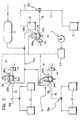
- a pneumatic circuit for a constant-level pneumatic suspension for buses or commercial vehicles is arranged to supply air springs 12 associated with wheels R of the vehicle and is pressurised by means of a compressed-air reservoir S in its turn supplied by a compressor C.
- the pneumatic circuit 10 has a central portion 10a connected directly to the reservoir S and branch portions 10b and 10c associated with the pairs of rear wheels and with the front axle of the vehicle, respectively.
- Levelling valves 14 of known type are interposed between the central portion 10a of the pneumatic circuit 10 and the branch portions 10b, 10c and are arranged to modulate the pressure of the air springs 12 in dependence on the conditions of loading of the vehicle.
- On/off solenoid valves 18 controlled by an electrical circuit 20 are mounted in pipes 16 connecting the levelling valves 14 and the air springs 12.
- the electrical circuit includes a tachometric switch 22 associated with the tachometer V of the vehicle, and a central electronic control unit 24 whose function will become clearer in the description below.
- the solenoid valves 18 When the vehicle is stationary, the solenoid valves 18 are open and enable the pressure of the air springs 12 to be regulated in order to keep the attitude of the vehicle constant (one is considering typical conditions with the bus stationary). When the vehicle starts to move, the solenoid valves 18 are activated at a predetermined speed imposed by means of the tachometric switch 22 and isolate the air springs 12 from the central portion 10a of the pneumatic circuit 10.
- auxiliary on/off valves 26 are interposed between the levelling valves 14 and the compressed-air reservoir S, such valves 26 being linked to the electric circuit 20.
- the simultaneous activation of the solenoid valves 18 and 26 by the tachometric switch 22 isolates both the air springs 12 and the levelling valves 14 completely from the remaining part of the pneumatic circuit.
- Figure 3 illustrates schematically a suspension which, according to a second embodiment, enables each pair constituted by an on/off solenoid valve 18 and an auxiliary on/off solenoid valve 26 to be combined in a single four-way pneumatic solenoid valve 28 having two first connectors 28a for connection to a closed-loop pipeline 30 in which the levelling valve 14 is mounted, and two second connectors 28b and 28c for connection to the compressed-air reservoir S and to the air springs 12, respectively.
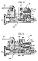
- FIG 4 illustrates a levelling valve 32 adapted for installation in a circuit of the type illustrated in Figure 2.
- the solenoid valve 32 has the advantage of combining the levelling valve and the on/off solenoid valve in a single body. This has a portion 32a which corresponds essentially to the known levelling valves and is operated by a lever 34 connected, for example, to an arm of the suspension.
- a second portion 32b of the levelling solenoid valve 32 is integral with the first portion 32a and enables the advantages described above to be achieved.
- the valve 32 includes a first connector 36 connected to the reservoir S, a second discharge connector 38, and a third connector 40 connected to the air springs 12.
- the portion 32b of the solenoid valve 32 has a valve seat 42 for cooperating with an obturator 44 constituted by the end of a rod 45 of an electromagnet 46.
- the rod 45 may take up a first, rest position (illustrated in Figure 4) under the action of a compression spring 47 and a second, operative position in which the obturator 44 cooperates with the seat 42 to isolate the connector 40 communicating with the air springs from the remaining portion 32a of the valve 32 which, being of known type, will not be described in detail.
- a T-connector is arranged on the axle controlled by one of these levelling valves 14, in known manner, in order to connect the main pipe 16 with two branch pipes 17.
- the T-connector in order to avoid a "transfer" of pressure from one air spring to the other during travel around bends, has a calibrated orifice for delaying or minimising the influence of the compressed-air flow from a spring which is outermost on the bend to a spring which is innermost on the bend. In each case, after cornering, a certain period is needed for the vehicle to regain its attitude as a result of the equalization of the pressure in the air springs.
- a further embodiment of the invention illustrated in Figure 5 has the additional object of preventing the said "transfer" of air from one spring to the other and thus of enabling the vehicle to regain its attitude more quickly when travelling along a straight line after the bend.
- an integrated levelling valve 50 is located in correspondence with the connector between the main pipe 16 and the branch pipe 17 connected to the air springs 12.
- the valve 50 has a first portion 50a entirely corresponding to the known levelling valves and a second portion 50b with an electromagnet 52 connected to the electrical circuit 20 of the suspension.
- the valve 50 has a first connector 54 communicating with the compressed-air reservoir S, a second discharge connector 56, and two third connectors 58a and 58b connected respectively to a right-hand spring and a left-hand spring of an axle of the suspension.
- the second portion 50b of the valve 50 has a seat 60 for cooperating with an obturator 62 constituted by the end of a rod 63 of the electromagnet 52.
- the rod 63 Adjacent the obturator 62, the rod 63 has an annular groove 64 which houses an annular sealing washer 66, for example an O-ring, adapted to slide sealingly on a cylindrical wall 68 coaxial with the seat 60.
- annular sealing washer 66 for example an O-ring
- Two apertures 68a and 68b which are spaced apart axially and which communicate with the two third connectors 58a and 58b are disposed in correspondence with the cylindrical wall 68.
- the obturator 62 In the operative configuration of the solenoid valve associated with the portion 50b of the valve 50 (the configuration illustrated in Figure 6), the obturator 62 is urged against the seat 60 so as to prevent communication between the third connectors 58a and 58b and the portion 50a of the valve.
- the washer 66 also prevents communication between the connectors 58a and 58b, isolating the right-hand and left-hand air springs of one axle of the suspension from each other.
- a compression spring 70 makes the rod 63 move so as to become disengaged from the seat 60 and brings the sealing washer 66 into a position such as to allow communication between the connectors 58a and 58b, enabling the regulating operation of the portion 50a of the valve 50.
Landscapes
- Engineering & Computer Science (AREA)
- Mechanical Engineering (AREA)
- Vehicle Body Suspensions (AREA)
- Fluid-Damping Devices (AREA)
Claims (5)
- Luft-Federung mit konstanter Lage für Fahrzeuge, insbesondere kommerzielle Fahrzeuge und Busse, die einen Druckluftkreis zum Verbinden einer Druckluftversorgungseinrichtung (S) mit Luftfedern (12) der Federung, eine Regelventileinrichtung (14), die dem Druckluftkreis zugeordnet ist, zum Regeln des Zuführens und Abführens von Druckluft zu oder von den Federn (12) als Ergebnis von Änderungen der Last des Fahrzeugs und Ein/Aus-Elektromagnetventile (18) enthält, die zwischen den Regelventilen (14) und den Luftfedern (12) angeordnet sind, zum Trennen der Luftfedern (12) von dem Druckluftkreis (10a), wenn das Fahrzeug eine vorbestimmte Geschwindigkeit überschreitet, dadurch gekennzeichnet, daß sie ferner Hilfs-Ein/Aus-Elektromagnetventile (26) enthält, die zwischen der Druckluftversorgungseinrichtung (S) und der Regelventileinrichtung (14) angeordnet sind und in Synchronismus mit den Ein/Aus-Elektromagnetventilen (18) betätigt werden, um die Teile des Druckluftkreises (16a) zwischen letzteren (18) und den Hilfs-Ein/Aus-Elektromagnetventilen (26) zu trennen.
- Federung nach Anspruch 1, dadurch gekennzeichnet daß die Ein/Aus-Elektromagnetventile (18) und die Hilfs-Ein/Aus-Elektromagnetventile (26) zu Paaren in einem einzigen Vierwege-Elektromagnetventil (28) kombiniert sind.
- Federung nach Anspruch 1, dadurch gekennzeichnet, daß der Druckluftkreis zumindest ein Paar von entsprechenden rechten und linken Luft-Federn (12) enthält, wobei ein Paar von Abzweigungsrohren (17) mit den Luftfedern (12) kommunizieren und mit einem einzigen Hauptrohr (16) für die Verbindung mit der Druckluftversorgungseinrichtung (S) verbunden sind und wobei die Federung für das Paar von Federn (12) ein Ausgleichsventil (50) enthält, das ein erstes Verbindungsteil (54), welches mit dem Hauptrohr (16) verbunden ist, ein zweites Abführungs-Verbindungsteil (56) und ein Paar von dritten Verbindungsteilen (58a, 58b) hat, wovon jedes mit dem betreffenden Abzweigungsrohr (17) verbunden ist, welches Ausgleichsventil (50) einen ersten Teil (50a) zum Modulieren des Drucks in den dritten Verbindungsteilen (58a, 58b) in Abhängigkeit von der Last des Fahrzeugs und einen zweiten Teil (50b) enthält, der einen Sitz (60) und einen entsprechenden Verschlußteil (62) zum Freigeben des Kommunizierens zwischen den Abzweigungsrohren (17) und dem ersten Teil (50a) des Elektromagnetventils in einer ersten Stellung und zum Unterbrechen der Luftströmung zwischen den dritten Verbindungsteilen (58a, 58b) und dem ersten und dem zweiten Verbindungsteilen (54, 56) und zum gleichzeitigen Trennen der dritten Verbindungsteile (58a, 58b) voneinander in einer zweiten Stellung enthält.
- Federung nach Anspruch 3, dadurch gekennzeichnet, daß der zweite Teil (50b) des Ausgleichsventils (50) einen Sitz (60) für den Verschlußteil (62) enthält, der koaxial mit einer zylindrischen Wand (68) angeordnet ist, wobei axial einen Abstand voneinander aufweisenden Öffnungen (68a, 68b) mit den Abzweigungsrohren (17) kommunizieren und wobei der Verschlußteil (62) einen ringförmigen luftdichten Teil (66) zur Positionierung in der zweiten Stellung des Verschlußteils (62) zwischen den Öffnungen (68a, 68b), um die Verzweigungsrohre (17) voneinander zu trennen, hat.
- Federung nach einem der vorhergehenden Ansprüche, dadurch gekennzeichnet, daß den Ein/Aus-Elektromagnetventilen Regelmittel zugeordnet sind, die einen Zeitschalter (24) für die periodische Deaktivierung der Ein/Aus-Elektromagnetventile (18, 26, 28, 32b, 50b), wenn sich das Fahrzeug bewegt, enthalten.
Applications Claiming Priority (2)
| Application Number | Priority Date | Filing Date | Title |
|---|---|---|---|
| IT6773388 | 1988-08-02 | ||
| IT67733/88A IT1223749B (it) | 1988-08-02 | 1988-08-02 | Sospensione pneumatica a livello costante per autoveicoli |
Publications (2)
| Publication Number | Publication Date |
|---|---|
| EP0354438A1 EP0354438A1 (de) | 1990-02-14 |
| EP0354438B1 true EP0354438B1 (de) | 1992-12-16 |
Family
ID=11304868
Family Applications (1)
| Application Number | Title | Priority Date | Filing Date |
|---|---|---|---|
| EP89114098A Expired EP0354438B1 (de) | 1988-08-02 | 1989-07-31 | Luftfederung mit konstanter Lage für Kraftfahrzeuge |
Country Status (4)
| Country | Link |
|---|---|
| EP (1) | EP0354438B1 (de) |
| DE (1) | DE68903903T2 (de) |
| ES (1) | ES2036764T3 (de) |
| IT (1) | IT1223749B (de) |
Cited By (1)
| Publication number | Priority date | Publication date | Assignee | Title |
|---|---|---|---|---|
| US7946603B2 (en) | 2005-06-24 | 2011-05-24 | Ride & Glide Pty Ltd | Air suspension system |
Families Citing this family (9)
| Publication number | Priority date | Publication date | Assignee | Title |
|---|---|---|---|---|
| FR2701069A1 (fr) * | 1993-01-29 | 1994-08-05 | Peugeot | Dispositif de commande de sécurité pour vérin hydraulique asservi. |
| US5333645A (en) * | 1993-06-07 | 1994-08-02 | Nai Neway, Inc. | Height control valve and dump valve therefor |
| US5326229A (en) * | 1993-06-28 | 1994-07-05 | Ford Motor Company | Integral air suspension compressor and engine air pump |
| DE9403577U1 (de) * | 1994-03-03 | 1994-06-30 | Xaver Fendt GmbH & Co, 87616 Marktoberdorf | Druckmittelversorgung für eine hydropneumatische, niveaugeregelte Achsfederung eines Arbeitsfahrzeuges |
| GB2298699B (en) * | 1995-03-02 | 1998-08-19 | Rover Group | A vehicle suspension system |
| KR0138404B1 (ko) * | 1995-07-31 | 1998-06-01 | 전성원 | 캡 에어 서스팬션용 레벨링 밸브 |
| ES2159453B1 (es) * | 1998-06-08 | 2002-04-01 | Accesorios Y Elevadores Valenc | Mecanismo de control de suspension de vehiculos. |
| DE102007001342A1 (de) | 2007-01-03 | 2008-07-17 | Siemens Ag | Regelung einer Luftfeder |
| CN101244685B (zh) * | 2008-01-24 | 2010-06-09 | 一汽解放青岛汽车厂 | 一种空气悬挂随动桥用气囊的电气控制装置及其控制方法 |
Family Cites Families (5)
| Publication number | Priority date | Publication date | Assignee | Title |
|---|---|---|---|---|
| US2687311A (en) * | 1949-12-08 | 1954-08-24 | Daimler Benz Ag | Device for regulating the vertical level of motor vehicles |
| US2787475A (en) * | 1955-08-30 | 1957-04-02 | Gen Motors Corp | Load controlled valve assembly for vehicle air spring |
| GB810644A (en) * | 1956-06-18 | 1959-03-18 | Gen Motors Corp | Improved height control system for motor vehicle air suspension |
| DE2129846A1 (de) * | 1971-06-16 | 1972-12-21 | Langen & Co | Stabilisierungsvorrichtung fuer Kraftfahrzeuge |
| US4733876A (en) * | 1986-12-17 | 1988-03-29 | Heider Merle J | Suspension and leveling system for a vehicle |
-
1988
- 1988-08-02 IT IT67733/88A patent/IT1223749B/it active
-
1989
- 1989-07-31 ES ES198989114098T patent/ES2036764T3/es not_active Expired - Lifetime
- 1989-07-31 EP EP89114098A patent/EP0354438B1/de not_active Expired
- 1989-07-31 DE DE8989114098T patent/DE68903903T2/de not_active Expired - Fee Related
Cited By (2)
| Publication number | Priority date | Publication date | Assignee | Title |
|---|---|---|---|---|
| US7946603B2 (en) | 2005-06-24 | 2011-05-24 | Ride & Glide Pty Ltd | Air suspension system |
| US8360451B2 (en) | 2005-06-24 | 2013-01-29 | Base Suspension Pty Ltd | Air suspension system |
Also Published As
| Publication number | Publication date |
|---|---|
| EP0354438A1 (de) | 1990-02-14 |
| DE68903903D1 (de) | 1993-01-28 |
| IT1223749B (it) | 1990-09-29 |
| DE68903903T2 (de) | 1993-04-22 |
| IT8867733A0 (it) | 1988-08-02 |
| ES2036764T3 (es) | 1993-06-01 |
Similar Documents
| Publication | Publication Date | Title |
|---|---|---|
| US5322321A (en) | Vehicle active suspension system | |
| US4421151A (en) | Tire-pressure regulating system | |
| US4483409A (en) | Integral hydraulic tilt-cab suspension and tilting apparatus | |
| EP0443613B1 (de) | Arbeitsfluidumkreis mit Leitungsdrucksteuerung für das Aktivaufhängungssystem eines Fahrzeugs | |
| EP0280740B1 (de) | Bremsdrucksteuersystem | |
| US4238128A (en) | Combination load-leveling and kneeling air suspension system | |
| JP2576834B2 (ja) | 機関車用ブレーキ制御システムのブレーキ管装気遮断装置 | |
| EP0354438A1 (de) | Luftfederung mit konstanter Lage für Kraftfahrzeuge | |
| EP0837806B1 (de) | Bremsanlage für anhänger und ein ventil zur anwendung darin | |
| JP3583255B2 (ja) | トレーラの制動制御のための制動装置 | |
| US2882068A (en) | Air suspension control system | |
| US3848932A (en) | Vehicle braking systems having height sensing proportioning valve | |
| US4629256A (en) | Fluid pressure braking system | |
| GB1532310A (en) | Vehicle brake system | |
| EP1091860A1 (de) | Verbesserte antriebsschlupf- und aufhängungsregelungseinrichtung | |
| US2962296A (en) | Fluid suspension and control system therefor | |
| US2882069A (en) | Air suspension control system | |
| EP0638036B1 (de) | Pilotrelaisventil mit lastkolben | |
| EP0367759B1 (de) | Druckverhältnisventil | |
| US3112118A (en) | Pneumatic spring system for motor vehicles | |
| EP0221031B1 (de) | Bremsventil für Anhänger-Druckluftbremsanlage | |
| PL77053B3 (pl) | Pneumatyczny przeciwslizgowy uklad hamulcowy | |
| US3232677A (en) | Fluid pressure brake control apparatus | |
| JPS58206409A (ja) | 自動車高調整装置 | |
| JPS6337723B2 (de) |
Legal Events
| Date | Code | Title | Description |
|---|---|---|---|
| PUAI | Public reference made under article 153(3) epc to a published international application that has entered the european phase |
Free format text: ORIGINAL CODE: 0009012 |
|
| AK | Designated contracting states |
Kind code of ref document: A1 Designated state(s): DE ES FR GB IT NL SE |
|
| 17P | Request for examination filed |
Effective date: 19900703 |
|
| 17Q | First examination report despatched |
Effective date: 19910910 |
|
| GRAA | (expected) grant |
Free format text: ORIGINAL CODE: 0009210 |
|
| AK | Designated contracting states |
Kind code of ref document: B1 Designated state(s): DE ES FR GB IT NL SE |
|
| ITF | It: translation for a ep patent filed | ||
| REF | Corresponds to: |
Ref document number: 68903903 Country of ref document: DE Date of ref document: 19930128 |
|
| ET | Fr: translation filed | ||
| REG | Reference to a national code |
Ref country code: ES Ref legal event code: FG2A Ref document number: 2036764 Country of ref document: ES Kind code of ref document: T3 |
|
| ET1 | Fr: translation filed ** revision of the translation of the patent or the claims | ||
| PLBE | No opposition filed within time limit |
Free format text: ORIGINAL CODE: 0009261 |
|
| STAA | Information on the status of an ep patent application or granted ep patent |
Free format text: STATUS: NO OPPOSITION FILED WITHIN TIME LIMIT |
|
| 26N | No opposition filed | ||
| EAL | Se: european patent in force in sweden |
Ref document number: 89114098.0 |
|
| REG | Reference to a national code |
Ref country code: GB Ref legal event code: IF02 |
|
| PGFP | Annual fee paid to national office [announced via postgrant information from national office to epo] |
Ref country code: SE Payment date: 20020531 Year of fee payment: 14 |
|
| PGFP | Annual fee paid to national office [announced via postgrant information from national office to epo] |
Ref country code: ES Payment date: 20020603 Year of fee payment: 14 |
|
| PGFP | Annual fee paid to national office [announced via postgrant information from national office to epo] |
Ref country code: GB Payment date: 20020612 Year of fee payment: 14 |
|
| PGFP | Annual fee paid to national office [announced via postgrant information from national office to epo] |
Ref country code: NL Payment date: 20020619 Year of fee payment: 14 Ref country code: DE Payment date: 20020619 Year of fee payment: 14 |
|
| PGFP | Annual fee paid to national office [announced via postgrant information from national office to epo] |
Ref country code: FR Payment date: 20020731 Year of fee payment: 14 |
|
| PG25 | Lapsed in a contracting state [announced via postgrant information from national office to epo] |
Ref country code: GB Free format text: LAPSE BECAUSE OF NON-PAYMENT OF DUE FEES Effective date: 20030731 |
|
| PG25 | Lapsed in a contracting state [announced via postgrant information from national office to epo] |
Ref country code: SE Free format text: LAPSE BECAUSE OF NON-PAYMENT OF DUE FEES Effective date: 20030801 Ref country code: ES Free format text: LAPSE BECAUSE OF NON-PAYMENT OF DUE FEES Effective date: 20030801 |
|
| PG25 | Lapsed in a contracting state [announced via postgrant information from national office to epo] |
Ref country code: NL Free format text: LAPSE BECAUSE OF NON-PAYMENT OF DUE FEES Effective date: 20040201 |
|
| PG25 | Lapsed in a contracting state [announced via postgrant information from national office to epo] |
Ref country code: DE Free format text: LAPSE BECAUSE OF NON-PAYMENT OF DUE FEES Effective date: 20040203 |
|
| GBPC | Gb: european patent ceased through non-payment of renewal fee |
Effective date: 20030731 |
|
| EUG | Se: european patent has lapsed | ||
| PG25 | Lapsed in a contracting state [announced via postgrant information from national office to epo] |
Ref country code: FR Free format text: LAPSE BECAUSE OF NON-PAYMENT OF DUE FEES Effective date: 20040331 |
|
| NLV4 | Nl: lapsed or anulled due to non-payment of the annual fee |
Effective date: 20040201 |
|
| REG | Reference to a national code |
Ref country code: FR Ref legal event code: ST |
|
| REG | Reference to a national code |
Ref country code: ES Ref legal event code: FD2A Effective date: 20030801 |
|
| PG25 | Lapsed in a contracting state [announced via postgrant information from national office to epo] |
Ref country code: IT Free format text: LAPSE BECAUSE OF NON-PAYMENT OF DUE FEES;WARNING: LAPSES OF ITALIAN PATENTS WITH EFFECTIVE DATE BEFORE 2007 MAY HAVE OCCURRED AT ANY TIME BEFORE 2007. THE CORRECT EFFECTIVE DATE MAY BE DIFFERENT FROM THE ONE RECORDED. Effective date: 20050731 |