EP0354467A2 - Machine-outil - Google Patents
Machine-outil Download PDFInfo
- Publication number
- EP0354467A2 EP0354467A2 EP89114304A EP89114304A EP0354467A2 EP 0354467 A2 EP0354467 A2 EP 0354467A2 EP 89114304 A EP89114304 A EP 89114304A EP 89114304 A EP89114304 A EP 89114304A EP 0354467 A2 EP0354467 A2 EP 0354467A2
- Authority
- EP
- European Patent Office
- Prior art keywords
- tool holder
- gripper
- tool
- receptacle
- fingers
- Prior art date
- Legal status (The legal status is an assumption and is not a legal conclusion. Google has not performed a legal analysis and makes no representation as to the accuracy of the status listed.)
- Granted
Links
Images


Classifications
-
- B—PERFORMING OPERATIONS; TRANSPORTING
- B23—MACHINE TOOLS; METAL-WORKING NOT OTHERWISE PROVIDED FOR
- B23Q—DETAILS, COMPONENTS, OR ACCESSORIES FOR MACHINE TOOLS, e.g. ARRANGEMENTS FOR COPYING OR CONTROLLING; MACHINE TOOLS IN GENERAL CHARACTERISED BY THE CONSTRUCTION OF PARTICULAR DETAILS OR COMPONENTS; COMBINATIONS OR ASSOCIATIONS OF METAL-WORKING MACHINES, NOT DIRECTED TO A PARTICULAR RESULT
- B23Q3/00—Devices holding, supporting, or positioning work or tools, of a kind normally removable from the machine
- B23Q3/155—Arrangements for automatic insertion or removal of tools, e.g. combined with manual handling
- B23Q3/157—Arrangements for automatic insertion or removal of tools, e.g. combined with manual handling of rotary tools
- B23Q3/15706—Arrangements for automatic insertion or removal of tools, e.g. combined with manual handling of rotary tools a single tool being inserted in a spindle directly from a storage device, i.e. without using transfer devices
-
- B—PERFORMING OPERATIONS; TRANSPORTING
- B23—MACHINE TOOLS; METAL-WORKING NOT OTHERWISE PROVIDED FOR
- B23Q—DETAILS, COMPONENTS, OR ACCESSORIES FOR MACHINE TOOLS, e.g. ARRANGEMENTS FOR COPYING OR CONTROLLING; MACHINE TOOLS IN GENERAL CHARACTERISED BY THE CONSTRUCTION OF PARTICULAR DETAILS OR COMPONENTS; COMBINATIONS OR ASSOCIATIONS OF METAL-WORKING MACHINES, NOT DIRECTED TO A PARTICULAR RESULT
- B23Q3/00—Devices holding, supporting, or positioning work or tools, of a kind normally removable from the machine
- B23Q3/155—Arrangements for automatic insertion or removal of tools, e.g. combined with manual handling
- B23Q3/1552—Arrangements for automatic insertion or removal of tools, e.g. combined with manual handling parts of devices for automatically inserting or removing tools
- B23Q3/1554—Transfer mechanisms, e.g. tool gripping arms; Drive mechanisms therefore
-
- B—PERFORMING OPERATIONS; TRANSPORTING
- B23—MACHINE TOOLS; METAL-WORKING NOT OTHERWISE PROVIDED FOR
- B23Q—DETAILS, COMPONENTS, OR ACCESSORIES FOR MACHINE TOOLS, e.g. ARRANGEMENTS FOR COPYING OR CONTROLLING; MACHINE TOOLS IN GENERAL CHARACTERISED BY THE CONSTRUCTION OF PARTICULAR DETAILS OR COMPONENTS; COMBINATIONS OR ASSOCIATIONS OF METAL-WORKING MACHINES, NOT DIRECTED TO A PARTICULAR RESULT
- B23Q3/00—Devices holding, supporting, or positioning work or tools, of a kind normally removable from the machine
- B23Q3/155—Arrangements for automatic insertion or removal of tools, e.g. combined with manual handling
- B23Q3/1552—Arrangements for automatic insertion or removal of tools, e.g. combined with manual handling parts of devices for automatically inserting or removing tools
- B23Q3/1554—Transfer mechanisms, e.g. tool gripping arms; Drive mechanisms therefore
- B23Q2003/155404—Transfer mechanisms, e.g. tool gripping arms; Drive mechanisms therefore the transfer mechanism comprising a single gripper
- B23Q2003/155411—Transfer mechanisms, e.g. tool gripping arms; Drive mechanisms therefore the transfer mechanism comprising a single gripper pivotable
-
- Y—GENERAL TAGGING OF NEW TECHNOLOGICAL DEVELOPMENTS; GENERAL TAGGING OF CROSS-SECTIONAL TECHNOLOGIES SPANNING OVER SEVERAL SECTIONS OF THE IPC; TECHNICAL SUBJECTS COVERED BY FORMER USPC CROSS-REFERENCE ART COLLECTIONS [XRACs] AND DIGESTS
- Y10—TECHNICAL SUBJECTS COVERED BY FORMER USPC
- Y10S—TECHNICAL SUBJECTS COVERED BY FORMER USPC CROSS-REFERENCE ART COLLECTIONS [XRACs] AND DIGESTS
- Y10S483/00—Tool changing
- Y10S483/90—Gripping portion engages tool simultanous with tool rotating in spindle
-
- Y—GENERAL TAGGING OF NEW TECHNOLOGICAL DEVELOPMENTS; GENERAL TAGGING OF CROSS-SECTIONAL TECHNOLOGIES SPANNING OVER SEVERAL SECTIONS OF THE IPC; TECHNICAL SUBJECTS COVERED BY FORMER USPC CROSS-REFERENCE ART COLLECTIONS [XRACs] AND DIGESTS
- Y10—TECHNICAL SUBJECTS COVERED BY FORMER USPC
- Y10T—TECHNICAL SUBJECTS COVERED BY FORMER US CLASSIFICATION
- Y10T483/00—Tool changing
- Y10T483/17—Tool changing including machine tool or component
- Y10T483/1733—Rotary spindle machine tool [e.g., milling machine, boring, machine, grinding machine, etc.]
- Y10T483/1736—Tool having specific mounting or work treating feature
- Y10T483/1743—Tool having specific mounting or work treating feature including means for angularly orienting tool and spindle
- Y10T483/1745—Spindle angularly oriented to align with tool
-
- Y—GENERAL TAGGING OF NEW TECHNOLOGICAL DEVELOPMENTS; GENERAL TAGGING OF CROSS-SECTIONAL TECHNOLOGIES SPANNING OVER SEVERAL SECTIONS OF THE IPC; TECHNICAL SUBJECTS COVERED BY FORMER USPC CROSS-REFERENCE ART COLLECTIONS [XRACs] AND DIGESTS
- Y10—TECHNICAL SUBJECTS COVERED BY FORMER USPC
- Y10T—TECHNICAL SUBJECTS COVERED BY FORMER US CLASSIFICATION
- Y10T483/00—Tool changing
- Y10T483/17—Tool changing including machine tool or component
- Y10T483/1733—Rotary spindle machine tool [e.g., milling machine, boring, machine, grinding machine, etc.]
- Y10T483/1748—Tool changer between spindle and matrix
- Y10T483/1752—Tool changer between spindle and matrix including tool holder pivotable about axis
Definitions
- the invention relates to a machine tool with a magazine containing a plurality of tool holders, from which a selected tool holder can be removed by means of an arm having a gripper and inserted into a working position in a rotating first receptacle of the machine tool, the tool holder in the gripper by means of a tool holder is held ring-shaped second receptacle, which has two mutually pivotable, each approximately a semicircular arc of the fingers forming the receptacle and the fingers are preferably provided with a profile that engages in a form-fitting manner in a circumferential groove of the tool holder, such that the tool holder is also in the gripper in the working position remains and turns in it.
- the known machine tool is a machining center for milling and drilling work, in which a plurality of arms are arranged around a vertical-axis spindle, which can be pivoted radially to the spindle axis and are provided with grippers for tool holders at their lower free ends.
- the tool holders are arranged in a ring above the spindle holder.
- one of the arms is pivoted downward and radially inward so that the tool holder is aligned with the spindle axis.
- the tool holder is now inserted into the rotating holder of the spindle.
- the grippers are designed in such a way that they encircle the tool holder in a ring shape, but allow the tool holder to rotate in the working position. As a result, the gripper can remain on the tool holder even while the tool is working and does not need to be swiveled towards or away from the tool holder in order to be replaced and replaced.
- the grippers in the known machine tool are provided with two fingers, each of which forms an approximately semicircular section of the ring-shaped receptacle for the tool holder.
- the fingers can be pivoted apart for loading the grippers, either about an axis parallel to the tool holder axis or about an axis perpendicular to it.
- the tool holder can now be inserted between the open fingers of the gripper in a direction that is essentially in the plane of the gripper receptacle, in order to then produce the all-encompassing receptacle for the tool holder by closing and latching the fingers.
- the tool holder is inserted into the rotating receptacle of the spindle in a defined rotational position.
- considerable path speeds of the arms and grippers occur when changing tools, the path of movement of the tool holder between spindle holder and magazine position when changing tools does not run in a straight line but along a multiple curved spatial path.
- the tool holders are therefore exposed to considerable dynamic loads when changing tools, so that it is by no means guaranteed that the rotational position of the tool holder between the magazine position and the working position or vice versa is maintained.
- the known machine tool has a vertical-axis headstock, which is arranged at a lateral distance from a magazine of tool holders.
- the tool holders are held in grippers, which in turn are arranged on a chain conveyor rotating in a horizontal plane.
- the grippers have an essentially U-shaped receptacle, ie they only encompass the standardized circumferential groove of the tool holder approximately over half the circumference.
- a transport device for the tool holder is provided between the headstock and the magazine and can be moved between the headstock and the magazine.
- the transport device has a horizontally arranged and rotatable symmetrical arm about a vertical axis, which is also provided at its two free ends with U-shaped receptacles for the tool holder. If a tool holder is to be removed from the magazine, the transport device moves one of the arm holders to a holder of the magazine, which is in a transfer position, and a tool holder is moved from the U-shaped holder of the magazine into the U by means of a slide -shaped shot of the arm pushed over. The arm is now swiveled by 180 ° and the tool is moved to the spindle holder and pulled into the spindle by moving it vertically.
- pawls are provided on each of the above-mentioned receptacles, which are each arranged in front of the free ends of the two legs of the U-shaped receptacles and on both sides from above or below engage standardized recesses on the circumference of the tool holder.
- a piston-cylinder unit is provided on the magazine, with which the locking pawls can be pivoted upwards or downwards out of the movement path of the tool holder when a tool is transferred via a linkage.
- the arrangement is such that the pawls on the magazine side also actuate the pawls of the arm of the transport device when they are actuated.
- the pawls of the transport device are spring-loaded and have no independent actuating device.
- the invention is based on the object of further developing a machine tool of the type mentioned in such a way that while maintaining the concept of the grippers remaining on the tool holder, a reliable definition of the Rotational position of the tool holder is also possible with a quick tool change and that the gripper can be loaded with tools manually in a simple manner.
- the gripper is provided with a spring-loaded locking lever, the free end of which engages as a locking lug in the unloaded state of the spring in a recess on the circumference of the tool holder and when inserting the tool holder into the first receptacle by means of a fixed stop against the Force of the spring is brought out of engagement with the recess, and that an actuating element spaced apart from the latching lug is provided on the latching lever for manually pivoting out the latching lug.
- the object on which the invention is based is completely achieved in this way because the locking lug engaging in the recess ensures a defined rotational position of the tool holder, even when high tool changing speeds are set. This is all the more so since in a gripper with a receptacle that surrounds the tool holder in a ring-shaped manner, only slight rotary movements with relatively low inertial forces can occur anyway, so that the latching lug can be fully effective even with a relatively small dimensioning.
- the actuating element which is spaced apart from the latching lug, is particularly advantageous for manually pivoting the latching lug out, because in this way the grippers can be equipped with tool holders in a particularly simple manner and additional servo devices are unnecessary.
- the locking lug is pivoted in a plane which is directed essentially at right angles to the direction in which the tool holder is removed from the gripper.
- This measure has the advantage that an unintentional pivoting of the locking lug due to inertial forces exerted by the tool holder is excluded because the direction of movement of the tool holder in the event of an unintentional rotation on the one hand and the locking lug on the other hand are perpendicular to each other for unlocking.
- yet another embodiment of the invention is particularly preferred, in which one of the fingers is provided with a latch and the movement paths of the latch partially overlap when the fingers are pivoted and the latching lever partially overlaps when the latch is pivoted, such that when the fingers are closed they form a circular receptacle which surrounds the tool holder on all sides only lies in the pivoted-in position of the locking lug outside the movement path of the bolt.
- This measure has the advantage that the fingers of the gripper can only be closed when the latch is pivoted completely into the recess. Otherwise, the locking lever acts as a baffle for the bolt and prevents the fingers from closing mechanically.
- standardized tool holders are provided with the mentioned recesses at circumferential positions offset by 180 °, so that it is conceivable that the tool holder sits incorrectly in the gripper by 180 °.
- the recesses are of different depths in standardized tool holders, so that it is possible to dimension the locking lug so large that it only fits into the deeper of the two recesses. Then it can be ensured with the arrangement described that the fingers of the gripper can only be closed when the latch actually sits in the lower of the two recesses and thus a clear rotational position of the tool holder is reached.
- the mechanical baffle described makes this easily recognizable for the assembly person, so that errors can be excluded.
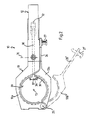
- 10 designates a tool changer overall, with which tool holder 11 can be exchanged and exchanged in a drilling and milling center for carrying out different machining operations.
- the tool changer 10 has an arm 12 which is provided at its free end with a gripper 13 for gripping and enclosing the tool holder 11.
- the movements of the tool changer 10 can be exerted, for example, via articulated rods 14 which act on the arm 12, as is known per se.
- Each of the tool holders used in the machine tool is. a separate arm is assigned and, depending on which tool is required, the arm in question is swiveled towards the spindle.
- the gripper 13 has two fingers 13a, 13b, which define a circular first receptacle 20.
- the arrangement is chosen such that the fingers 13a, 13b each form approximately a semicircular section of the first receptacle 20.
- the fingers 13a, 13b as can be seen from FIG. 1, are provided with a circumferential profile 21 which, with a certain amount of play, is adapted to a standardized circumferential groove 22 of the tool holder 11.
- the tool holder 11 is therefore axially fixed in the gripper 13, but is rotatably arranged.
- the fingers 13a, 13b can be pivoted against each other from the position shown in solid line in FIG. 2, for example about a first axis 25 which runs perpendicular to the plane of the drawing in FIG. 2.
- the dot-dash line 13b ' is shown in a partially pivoted position. It can easily be seen from this that if the finger 13b is pivoted sufficiently far relative to the finger 13a rigidly connected to the gripper 13, a tool holder can be inserted into the receptacle 20 and then fixed by closing the fingers 13a, 13b.
- the direction of loading or unloading the tool holder 11 lies in the plane of the drawing in FIG. 2.
- the finger 13b is provided with an extension 26 which carries a push button 27 at its free end.
- the push button 27 can be designed in the manner of a ballpoint pen mechanism, such that when the fingers 13a, 13b are closed, the push button 27 engages in a corresponding socket in the arm 12 and, on the other hand, by pressing the push button 27 again, this latching connection for opening the fingers 13a, 13b can be solved again.
- a locking lever 30 is arranged in the arm 12, which can be pivoted about a second axis 31 perpendicular to the plane of the drawing in FIG. 1.
- an actuating button 32 is formed to the In Fig. 1 upper free end of the two-armed locking lever 30, an actuating button 32 is formed.
- the actuation button 30 is on the other hand connected to a compression spring 34, the other end of which is arranged in a blind hole 35 of the arm 12.
- the locking lever 30 In the idle state, ie with the spring 34 relaxed, the locking lever 30 is in the position shown continuously in FIG. 1. In this rest position, the actuation button 32 projects beyond the rear of the arm 12.
- a locking lug 37 is formed, which has a T-shaped shape in the plan view of FIG. 2.
- the locking lug 37 is dimensioned such that it engages in a recess 38 on the circumference of the tool holder 11.
- tool holders 11 of the type of interest here are provided on their circumference 39 with two cutouts 38a, 38b which are diametrically opposite one another.
- One of the cutouts, in FIG. 3 the cutout 38a, is formed radially deeper than the other cutout 38b.
- the locking lug 37 is now dimensioned such that it completely fills the deeper recess 38a. This is the case with the rest position of the locking lever 30 shown in solid lines in FIG. 1.
- the locking lever 30 is provided on the lower lever arm between the second axis 31 and the locking lug 37 with an upwardly projecting projection 45.
- the projection 45 protrudes through a through hole 46 in the arm 12 and is therefore accessible from above.
- a fixed stop 48 is arranged in the form of a pin projecting below. If the tool changer 10 is now moved upward in the direction of the arrow 50 shown in FIG. 1, or the spindle is moved downward, around the tool holder 11 with its standard cone in the direction of its axis 51 into a second holder 52, namely the rotating conical holder of the Bring headstock, the projection 45 comes into contact with the stop 48, so that the locking lever 30 is rotated counterclockwise in the illustration of FIG. 1 with further movement of the tool changer 10. This is done against the force of the compression spring 34 and causes the latch 37 from the position shown in solid line in Fig. 1 in the dash-dotted position 37 '. In this position, the locking lug 37 'is disengaged from the recess 38a, so that the tool holder 11 can now freely rotate about its axis 51.
- the finger 13b is provided on its underside with a bolt 55, the path of movement of which when the fingers 13a, 13b are closed intersects the path of movement of the locking lever 30 when it is pivoted about the second axis 31. If the locking lever 30 is in the basic position shown in solid line in FIG. 1, the underside of the locking lever 30 including the locking lug 37 is aligned with the underside of the gripper 13. In this case, the finger 13b can be pivoted towards the gripper 13 because the top side of the bolt 55 is also aligned with the underside of the gripper 13.
Landscapes
- Engineering & Computer Science (AREA)
- Mechanical Engineering (AREA)
- Automatic Tool Replacement In Machine Tools (AREA)
- Auxiliary Devices For Machine Tools (AREA)
Applications Claiming Priority (2)
| Application Number | Priority Date | Filing Date | Title |
|---|---|---|---|
| DE3827053 | 1988-08-10 | ||
| DE3827053A DE3827053A1 (de) | 1988-08-10 | 1988-08-10 | Werkzeugmaschine |
Publications (3)
| Publication Number | Publication Date |
|---|---|
| EP0354467A2 true EP0354467A2 (fr) | 1990-02-14 |
| EP0354467A3 EP0354467A3 (en) | 1990-08-29 |
| EP0354467B1 EP0354467B1 (fr) | 1993-02-24 |
Family
ID=6360537
Family Applications (1)
| Application Number | Title | Priority Date | Filing Date |
|---|---|---|---|
| EP89114304A Expired - Lifetime EP0354467B1 (fr) | 1988-08-10 | 1989-08-03 | Machine-outil |
Country Status (5)
| Country | Link |
|---|---|
| US (1) | US4827599A (fr) |
| EP (1) | EP0354467B1 (fr) |
| JP (1) | JPH0725003B2 (fr) |
| DE (2) | DE3827053A1 (fr) |
| ES (1) | ES2039772T3 (fr) |
Cited By (2)
| Publication number | Priority date | Publication date | Assignee | Title |
|---|---|---|---|---|
| EP1477269A1 (fr) * | 2003-05-16 | 2004-11-17 | Chiron-Werke GmbH & Co. KG | Machine outil |
| US7115082B2 (en) | 2003-05-16 | 2006-10-03 | Chiron-Werke Gmbh & Co. Kg | Machine tool |
Families Citing this family (7)
| Publication number | Priority date | Publication date | Assignee | Title |
|---|---|---|---|---|
| JP3687857B2 (ja) * | 1992-05-29 | 2005-08-24 | 澁谷工業株式会社 | 回転式容器処理装置のワークヘッド交換装置 |
| DE19716491C2 (de) * | 1997-04-19 | 1999-07-29 | Chiron Werke Gmbh | Werkzeugmaschine zur Bearbeitung von Werkstückhohlräumen |
| DE10039525A1 (de) | 2000-08-08 | 2002-02-21 | Grob Werke Dr H C Mult Dipl In | Werkzeugmaschine mit Greifer und oder Werkzeugmagazinsystem |
| US6641511B2 (en) * | 2000-08-31 | 2003-11-04 | Hurco Companies, Inc. | Movable arm activated tool changer for machine tool system |
| GB0207298D0 (en) * | 2002-03-28 | 2002-05-08 | Renishaw Plc | Apparatus for changing operating modules on a coordinate positioning machine |
| CN102528509A (zh) * | 2012-02-08 | 2012-07-04 | 昆山北钜机械有限公司 | 中心加工机刀库机构 |
| JP6882234B2 (ja) * | 2018-07-13 | 2021-06-02 | ファナック株式会社 | 工作機械 |
Family Cites Families (24)
| Publication number | Priority date | Publication date | Assignee | Title |
|---|---|---|---|---|
| US3327386A (en) * | 1965-12-27 | 1967-06-27 | De Vlieg Machine Co | Tool handling mechanism and tool for use therewith |
| DE1904093C3 (de) * | 1967-09-25 | 1975-06-12 | The Carlton Machine Tool Company, Cincinnati, Ohio (V.St.A.) | Werkzeugmaschine mit selbsttätigem Werkzeugwechsel |
| US3526033A (en) * | 1967-09-19 | 1970-09-01 | Pratt & Whitney Inc | Machine tool with tool changer |
| US3722711A (en) * | 1970-04-15 | 1973-03-27 | Cincinnati Milacron Inc | Machine tool |
| GB1394571A (en) * | 1971-09-09 | 1975-05-21 | Molins Ltd | Tool-holding devices |
| DE2525212B2 (de) * | 1975-06-06 | 1980-02-07 | Norte-Klessmann Gmbh & Co Kg, 4830 Guetersloh | Werkzeugaufnahme |
| SU657954A1 (ru) * | 1977-03-23 | 1979-04-25 | Ульяновское Головное Специальное Конструкторское Бюро Тяжелых И Фрезерных Станков | Устройство дл автоматической смены инструмента |
| SU703300A1 (ru) * | 1978-01-02 | 1979-12-18 | Ордена Трудового Красного Знамени Экспериментальный Научно-Исследовательский Институт Металлорежущих Станков | Захват дл автоматической смены инструментальных оправок |
| DE2819607C2 (de) * | 1978-05-05 | 1984-08-23 | Ex-Cell-O Gmbh, 7332 Eislingen | Magazin zum Speichern von mit Werkzeugen bestückten Werkzeughaltern für Werkzeugmaschinen |
| DD137676A1 (de) * | 1978-07-13 | 1979-09-19 | Gerhard Starke | Greifer fuer die werkzeugwechseleinrichtung einer werkzeugmaschine |
| JPS5558943A (en) * | 1978-10-27 | 1980-05-02 | Toyoda Mach Works Ltd | Tool exchanger |
| JPS55120943A (en) * | 1979-03-09 | 1980-09-17 | Brother Ind Ltd | Tool replacing device for machine tool |
| JPS55144944A (en) * | 1979-04-25 | 1980-11-12 | Toyoda Mach Works Ltd | Finger locking unit for tool exchange device |
| US4338709A (en) * | 1979-05-01 | 1982-07-13 | Straub Hans F | Magazine for storing toolholders with tools mounted therein for machine tools |
| SU904980A1 (ru) * | 1980-04-14 | 1982-02-15 | Предприятие П/Я В-8889 | Устройство дл фиксации инструмента |
| IT1136067B (it) * | 1980-10-03 | 1986-08-27 | Pear Mecc Arrigo Pecchioli | Attrezzatura per la manipolazione di utensili tradizionali in una macchina utensile fresatrice o simile |
| JPS5845834A (ja) * | 1981-09-09 | 1983-03-17 | Toyoda Mach Works Ltd | 工具交換装置 |
| JPS5988236A (ja) * | 1982-11-04 | 1984-05-22 | Enshu Ltd | 主軸無制動式工具交換装置 |
| DD214322A1 (de) * | 1983-03-10 | 1984-10-10 | Werkzeugmasch Heckert Veb | Greifer fuer rotationssymmetrische teile |
| DE3320874A1 (de) * | 1983-06-09 | 1984-12-13 | Chiron-Werke Gmbh, 7200 Tuttlingen | Werkzeugmaschine |
| DE3404497A1 (de) * | 1984-02-09 | 1985-08-29 | Kelch Gmbh + Co Werkzeugmaschinenfabrik, 7060 Schorndorf | Verfahren und vorrichtung zur drehausrichtung einer werkzeugmaschinen-arbeitsspindel |
| SU1187949A1 (ru) * | 1984-05-28 | 1985-10-30 | Одесское Специальное Конструкторское Бюро Алмазно-Расточных И Радиально-Сверлильных Станков | Инструментальный магазин |
| DE3531160A1 (de) * | 1985-08-31 | 1987-03-12 | Honsberg Gmbh Geb | Werkzeugwechsler fuer eine werkzeugmaschine |
| DE3620364C1 (de) * | 1986-06-18 | 1988-01-21 | Chiron Werke Gmbh | Greifer fuer einen Werkzeughalter einer Werkzeugmaschine |
-
1988
- 1988-08-10 DE DE3827053A patent/DE3827053A1/de active Granted
- 1988-08-22 US US07/234,884 patent/US4827599A/en not_active Expired - Fee Related
-
1989
- 1989-08-03 DE DE8989114304T patent/DE58903594D1/de not_active Expired - Fee Related
- 1989-08-03 ES ES198989114304T patent/ES2039772T3/es not_active Expired - Lifetime
- 1989-08-03 EP EP89114304A patent/EP0354467B1/fr not_active Expired - Lifetime
- 1989-08-09 JP JP1204945A patent/JPH0725003B2/ja not_active Expired - Fee Related
Cited By (5)
| Publication number | Priority date | Publication date | Assignee | Title |
|---|---|---|---|---|
| EP1477269A1 (fr) * | 2003-05-16 | 2004-11-17 | Chiron-Werke GmbH & Co. KG | Machine outil |
| DE10323592A1 (de) * | 2003-05-16 | 2004-12-09 | Chiron-Werke Gmbh & Co Kg | Werkzeugmaschine |
| DE10323592B4 (de) * | 2003-05-16 | 2006-03-23 | Chiron-Werke Gmbh & Co Kg | Werkzeugmaschine |
| US7115082B2 (en) | 2003-05-16 | 2006-10-03 | Chiron-Werke Gmbh & Co. Kg | Machine tool |
| US7211033B2 (en) | 2003-05-16 | 2007-05-01 | Chiron-Werke Gmbh & Co. Kg | Machine tool |
Also Published As
| Publication number | Publication date |
|---|---|
| JPH0283136A (ja) | 1990-03-23 |
| JPH0725003B2 (ja) | 1995-03-22 |
| US4827599A (en) | 1989-05-09 |
| EP0354467A3 (en) | 1990-08-29 |
| DE3827053A1 (de) | 1990-02-15 |
| ES2039772T3 (es) | 1993-10-01 |
| DE58903594D1 (de) | 1993-04-01 |
| DE3827053C2 (fr) | 1992-03-19 |
| EP0354467B1 (fr) | 1993-02-24 |
Similar Documents
| Publication | Publication Date | Title |
|---|---|---|
| DE60005074T2 (de) | Batteriebetriebene Handwerkzeugmaschine | |
| EP0291828B1 (fr) | Pince de préhension pour outils de machine-outil | |
| DE4407854B4 (de) | Bohrfutter | |
| EP0620068B1 (fr) | Mandrin de perçage | |
| DE69800727T2 (de) | Verriegelungsvorrichtung eines Mechanismus zum Schnappen und Trennen eines elektrischen Schalters | |
| DE3112097C2 (de) | "Sicherheitsschalter" | |
| EP0023951B1 (fr) | Outil à main entraîné par un moteur, en particulier outil à usages multiples pour bricoleurs | |
| DE10249179A1 (de) | Spannfutter mit Schnellwechselmechanismus | |
| DE4000928C2 (fr) | ||
| DE19624486A1 (de) | Werkzeughalter zur Verwendung in einem automatischen Werkzeugwechsler | |
| DE3105951C2 (de) | Kraftwerkzeug | |
| EP0354467B1 (fr) | Machine-outil | |
| EP1572403B1 (fr) | Mandrin de serrage et tige de serrage destinee a celui-ci | |
| DE3734718C2 (fr) | ||
| DE69418195T2 (de) | Handhabungsvorrichtung für bohrgestänge | |
| DE2516586A1 (de) | Werkzeugtransportvorrichtung | |
| EP0598207B1 (fr) | Mandrin de forage | |
| DE3507349A1 (de) | Schloss | |
| DE885510C (de) | Spannfutter | |
| DE3423959A1 (de) | Greifschuhvorrichtung zur anordnung an einem fahrzeugrad | |
| EP1314499B1 (fr) | Mandrin de serrage sans clé | |
| DE8514675U1 (de) | Rohrzange | |
| DE3404220C2 (de) | Versenkbar angeordneter Türgriff, insbesondere für Backofentüren von Herden | |
| EP0308822B1 (fr) | Machine-outil | |
| DE102006009432B4 (de) | Greifvorrichtung für eine Werkzeugwechselvorrichtung |
Legal Events
| Date | Code | Title | Description |
|---|---|---|---|
| PUAI | Public reference made under article 153(3) epc to a published international application that has entered the european phase |
Free format text: ORIGINAL CODE: 0009012 |
|
| AK | Designated contracting states |
Kind code of ref document: A2 Designated state(s): CH DE ES FR GB IT LI SE |
|
| PUAL | Search report despatched |
Free format text: ORIGINAL CODE: 0009013 |
|
| AK | Designated contracting states |
Kind code of ref document: A3 Designated state(s): CH DE ES FR GB IT LI SE |
|
| 17P | Request for examination filed |
Effective date: 19901220 |
|
| 17Q | First examination report despatched |
Effective date: 19910802 |
|
| GRAA | (expected) grant |
Free format text: ORIGINAL CODE: 0009210 |
|
| AK | Designated contracting states |
Kind code of ref document: B1 Designated state(s): CH DE ES FR GB IT LI SE |
|
| PG25 | Lapsed in a contracting state [announced via postgrant information from national office to epo] |
Ref country code: SE Effective date: 19930224 |
|
| ITF | It: translation for a ep patent filed | ||
| REF | Corresponds to: |
Ref document number: 58903594 Country of ref document: DE Date of ref document: 19930401 |
|
| ET | Fr: translation filed | ||
| GBT | Gb: translation of ep patent filed (gb section 77(6)(a)/1977) |
Effective date: 19930526 |
|
| PG25 | Lapsed in a contracting state [announced via postgrant information from national office to epo] |
Ref country code: LI Effective date: 19930831 Ref country code: CH Effective date: 19930831 |
|
| REG | Reference to a national code |
Ref country code: ES Ref legal event code: FG2A Ref document number: 2039772 Country of ref document: ES Kind code of ref document: T3 |
|
| PLBE | No opposition filed within time limit |
Free format text: ORIGINAL CODE: 0009261 |
|
| STAA | Information on the status of an ep patent application or granted ep patent |
Free format text: STATUS: NO OPPOSITION FILED WITHIN TIME LIMIT |
|
| 26N | No opposition filed | ||
| REG | Reference to a national code |
Ref country code: CH Ref legal event code: PL |
|
| PGFP | Annual fee paid to national office [announced via postgrant information from national office to epo] |
Ref country code: GB Payment date: 20010724 Year of fee payment: 13 |
|
| PGFP | Annual fee paid to national office [announced via postgrant information from national office to epo] |
Ref country code: FR Payment date: 20010726 Year of fee payment: 13 |
|
| REG | Reference to a national code |
Ref country code: GB Ref legal event code: IF02 |
|
| PG25 | Lapsed in a contracting state [announced via postgrant information from national office to epo] |
Ref country code: GB Free format text: LAPSE BECAUSE OF NON-PAYMENT OF DUE FEES Effective date: 20020803 |
|
| GBPC | Gb: european patent ceased through non-payment of renewal fee |
Effective date: 20020803 |
|
| PG25 | Lapsed in a contracting state [announced via postgrant information from national office to epo] |
Ref country code: FR Free format text: LAPSE BECAUSE OF NON-PAYMENT OF DUE FEES Effective date: 20030430 |
|
| REG | Reference to a national code |
Ref country code: FR Ref legal event code: ST |
|
| PGFP | Annual fee paid to national office [announced via postgrant information from national office to epo] |
Ref country code: ES Payment date: 20030807 Year of fee payment: 15 |
|
| PG25 | Lapsed in a contracting state [announced via postgrant information from national office to epo] |
Ref country code: ES Free format text: LAPSE BECAUSE OF NON-PAYMENT OF DUE FEES Effective date: 20040804 |
|
| PG25 | Lapsed in a contracting state [announced via postgrant information from national office to epo] |
Ref country code: IT Free format text: LAPSE BECAUSE OF NON-PAYMENT OF DUE FEES;WARNING: LAPSES OF ITALIAN PATENTS WITH EFFECTIVE DATE BEFORE 2007 MAY HAVE OCCURRED AT ANY TIME BEFORE 2007. THE CORRECT EFFECTIVE DATE MAY BE DIFFERENT FROM THE ONE RECORDED. Effective date: 20050803 |
|
| PGFP | Annual fee paid to national office [announced via postgrant information from national office to epo] |
Ref country code: DE Payment date: 20050921 Year of fee payment: 17 |
|
| REG | Reference to a national code |
Ref country code: ES Ref legal event code: FD2A Effective date: 20040804 |
|
| PG25 | Lapsed in a contracting state [announced via postgrant information from national office to epo] |
Ref country code: DE Free format text: LAPSE BECAUSE OF NON-PAYMENT OF DUE FEES Effective date: 20070301 |