EP0354468A2 - Flächenhafter Strahler - Google Patents
Flächenhafter Strahler Download PDFInfo
- Publication number
- EP0354468A2 EP0354468A2 EP89114320A EP89114320A EP0354468A2 EP 0354468 A2 EP0354468 A2 EP 0354468A2 EP 89114320 A EP89114320 A EP 89114320A EP 89114320 A EP89114320 A EP 89114320A EP 0354468 A2 EP0354468 A2 EP 0354468A2
- Authority
- EP
- European Patent Office
- Prior art keywords
- mounting plate
- reflectors
- flat
- transparent mounting
- plastic body
- Prior art date
- Legal status (The legal status is an assumption and is not a legal conclusion. Google has not performed a legal analysis and makes no representation as to the accuracy of the status listed.)
- Withdrawn
Links
Images

Classifications
-
- H—ELECTRICITY
- H10—SEMICONDUCTOR DEVICES; ELECTRIC SOLID-STATE DEVICES NOT OTHERWISE PROVIDED FOR
- H10W—GENERIC PACKAGES, INTERCONNECTIONS, CONNECTORS OR OTHER CONSTRUCTIONAL DETAILS OF DEVICES COVERED BY CLASS H10
- H10W90/00—Package configurations
-
- B—PERFORMING OPERATIONS; TRANSPORTING
- B60—VEHICLES IN GENERAL
- B60Q—ARRANGEMENT OF SIGNALLING OR LIGHTING DEVICES, THE MOUNTING OR SUPPORTING THEREOF OR CIRCUITS THEREFOR, FOR VEHICLES IN GENERAL
- B60Q1/00—Arrangement of optical signalling or lighting devices, the mounting or supporting thereof or circuits therefor
- B60Q1/26—Arrangement of optical signalling or lighting devices, the mounting or supporting thereof or circuits therefor the devices being primarily intended to indicate the vehicle, or parts thereof, or to give signals, to other traffic
- B60Q1/2696—Mounting of devices using LEDs
-
- F—MECHANICAL ENGINEERING; LIGHTING; HEATING; WEAPONS; BLASTING
- F21—LIGHTING
- F21S—NON-PORTABLE LIGHTING DEVICES; SYSTEMS THEREOF; VEHICLE LIGHTING DEVICES SPECIALLY ADAPTED FOR VEHICLE EXTERIORS
- F21S41/00—Illuminating devices specially adapted for vehicle exteriors, e.g. headlamps
- F21S41/10—Illuminating devices specially adapted for vehicle exteriors, e.g. headlamps characterised by the light source
- F21S41/14—Illuminating devices specially adapted for vehicle exteriors, e.g. headlamps characterised by the light source characterised by the type of light source
- F21S41/141—Light emitting diodes [LED]
- F21S41/143—Light emitting diodes [LED] the main emission direction of the LED being parallel to the optical axis of the illuminating device
-
- F—MECHANICAL ENGINEERING; LIGHTING; HEATING; WEAPONS; BLASTING
- F21—LIGHTING
- F21S—NON-PORTABLE LIGHTING DEVICES; SYSTEMS THEREOF; VEHICLE LIGHTING DEVICES SPECIALLY ADAPTED FOR VEHICLE EXTERIORS
- F21S41/00—Illuminating devices specially adapted for vehicle exteriors, e.g. headlamps
- F21S41/10—Illuminating devices specially adapted for vehicle exteriors, e.g. headlamps characterised by the light source
- F21S41/14—Illuminating devices specially adapted for vehicle exteriors, e.g. headlamps characterised by the light source characterised by the type of light source
- F21S41/141—Light emitting diodes [LED]
- F21S41/151—Light emitting diodes [LED] arranged in one or more lines
- F21S41/153—Light emitting diodes [LED] arranged in one or more lines arranged in a matrix
-
- F—MECHANICAL ENGINEERING; LIGHTING; HEATING; WEAPONS; BLASTING
- F21—LIGHTING
- F21S—NON-PORTABLE LIGHTING DEVICES; SYSTEMS THEREOF; VEHICLE LIGHTING DEVICES SPECIALLY ADAPTED FOR VEHICLE EXTERIORS
- F21S41/00—Illuminating devices specially adapted for vehicle exteriors, e.g. headlamps
- F21S41/30—Illuminating devices specially adapted for vehicle exteriors, e.g. headlamps characterised by reflectors
- F21S41/32—Optical layout thereof
- F21S41/322—Optical layout thereof the reflector using total internal reflection
-
- F—MECHANICAL ENGINEERING; LIGHTING; HEATING; WEAPONS; BLASTING
- F21—LIGHTING
- F21S—NON-PORTABLE LIGHTING DEVICES; SYSTEMS THEREOF; VEHICLE LIGHTING DEVICES SPECIALLY ADAPTED FOR VEHICLE EXTERIORS
- F21S43/00—Signalling devices specially adapted for vehicle exteriors, e.g. brake lamps, direction indicator lights or reversing lights
- F21S43/10—Signalling devices specially adapted for vehicle exteriors, e.g. brake lamps, direction indicator lights or reversing lights characterised by the light source
- F21S43/13—Signalling devices specially adapted for vehicle exteriors, e.g. brake lamps, direction indicator lights or reversing lights characterised by the light source characterised by the type of light source
- F21S43/14—Light emitting diodes [LED]
-
- F—MECHANICAL ENGINEERING; LIGHTING; HEATING; WEAPONS; BLASTING
- F21—LIGHTING
- F21S—NON-PORTABLE LIGHTING DEVICES; SYSTEMS THEREOF; VEHICLE LIGHTING DEVICES SPECIALLY ADAPTED FOR VEHICLE EXTERIORS
- F21S43/00—Signalling devices specially adapted for vehicle exteriors, e.g. brake lamps, direction indicator lights or reversing lights
- F21S43/20—Signalling devices specially adapted for vehicle exteriors, e.g. brake lamps, direction indicator lights or reversing lights characterised by refractors, transparent cover plates, light guides or filters
- F21S43/281—Materials thereof; Structures thereof; Properties thereof; Coatings thereof
- F21S43/28135—Structures encapsulating the light source
-
- F—MECHANICAL ENGINEERING; LIGHTING; HEATING; WEAPONS; BLASTING
- F21—LIGHTING
- F21Y—INDEXING SCHEME ASSOCIATED WITH SUBCLASSES F21K, F21L, F21S and F21V, RELATING TO THE FORM OR THE KIND OF THE LIGHT SOURCES OR OF THE COLOUR OF THE LIGHT EMITTED
- F21Y2105/00—Planar light sources
- F21Y2105/10—Planar light sources comprising a two-dimensional [2D] array of point-like light-generating elements
-
- F—MECHANICAL ENGINEERING; LIGHTING; HEATING; WEAPONS; BLASTING
- F21—LIGHTING
- F21Y—INDEXING SCHEME ASSOCIATED WITH SUBCLASSES F21K, F21L, F21S and F21V, RELATING TO THE FORM OR THE KIND OF THE LIGHT SOURCES OR OF THE COLOUR OF THE LIGHT EMITTED
- F21Y2109/00—Light sources with light-generating elements disposed on transparent or translucent supports or substrates
-
- F—MECHANICAL ENGINEERING; LIGHTING; HEATING; WEAPONS; BLASTING
- F21—LIGHTING
- F21Y—INDEXING SCHEME ASSOCIATED WITH SUBCLASSES F21K, F21L, F21S and F21V, RELATING TO THE FORM OR THE KIND OF THE LIGHT SOURCES OR OF THE COLOUR OF THE LIGHT EMITTED
- F21Y2115/00—Light-generating elements of semiconductor light sources
- F21Y2115/10—Light-emitting diodes [LED]
-
- H—ELECTRICITY
- H10—SEMICONDUCTOR DEVICES; ELECTRIC SOLID-STATE DEVICES NOT OTHERWISE PROVIDED FOR
- H10H—INORGANIC LIGHT-EMITTING SEMICONDUCTOR DEVICES HAVING POTENTIAL BARRIERS
- H10H20/00—Individual inorganic light-emitting semiconductor devices having potential barriers, e.g. light-emitting diodes [LED]
- H10H20/80—Constructional details
- H10H20/85—Packages
- H10H20/852—Encapsulations
- H10H20/853—Encapsulations characterised by their shape
-
- H—ELECTRICITY
- H10—SEMICONDUCTOR DEVICES; ELECTRIC SOLID-STATE DEVICES NOT OTHERWISE PROVIDED FOR
- H10H—INORGANIC LIGHT-EMITTING SEMICONDUCTOR DEVICES HAVING POTENTIAL BARRIERS
- H10H20/00—Individual inorganic light-emitting semiconductor devices having potential barriers, e.g. light-emitting diodes [LED]
- H10H20/80—Constructional details
- H10H20/85—Packages
- H10H20/852—Encapsulations
- H10H20/854—Encapsulations characterised by their material, e.g. epoxy or silicone resins
-
- H—ELECTRICITY
- H10—SEMICONDUCTOR DEVICES; ELECTRIC SOLID-STATE DEVICES NOT OTHERWISE PROVIDED FOR
- H10H—INORGANIC LIGHT-EMITTING SEMICONDUCTOR DEVICES HAVING POTENTIAL BARRIERS
- H10H20/00—Individual inorganic light-emitting semiconductor devices having potential barriers, e.g. light-emitting diodes [LED]
- H10H20/80—Constructional details
- H10H20/85—Packages
- H10H20/855—Optical field-shaping means, e.g. lenses
- H10H20/856—Reflecting means
-
- H—ELECTRICITY
- H10—SEMICONDUCTOR DEVICES; ELECTRIC SOLID-STATE DEVICES NOT OTHERWISE PROVIDED FOR
- H10W—GENERIC PACKAGES, INTERCONNECTIONS, CONNECTORS OR OTHER CONSTRUCTIONAL DETAILS OF DEVICES COVERED BY CLASS H10
- H10W72/00—Interconnections or connectors in packages
- H10W72/851—Dispositions of multiple connectors or interconnections
- H10W72/874—On different surfaces
- H10W72/884—Die-attach connectors and bond wires
-
- H—ELECTRICITY
- H10—SEMICONDUCTOR DEVICES; ELECTRIC SOLID-STATE DEVICES NOT OTHERWISE PROVIDED FOR
- H10W—GENERIC PACKAGES, INTERCONNECTIONS, CONNECTORS OR OTHER CONSTRUCTIONAL DETAILS OF DEVICES COVERED BY CLASS H10
- H10W90/00—Package configurations
- H10W90/701—Package configurations characterised by the relative positions of pads or connectors relative to package parts
- H10W90/731—Package configurations characterised by the relative positions of pads or connectors relative to package parts of die-attach connectors
- H10W90/734—Package configurations characterised by the relative positions of pads or connectors relative to package parts of die-attach connectors between a chip and a stacked insulating package substrate, interposer or RDL
-
- Y—GENERAL TAGGING OF NEW TECHNOLOGICAL DEVELOPMENTS; GENERAL TAGGING OF CROSS-SECTIONAL TECHNOLOGIES SPANNING OVER SEVERAL SECTIONS OF THE IPC; TECHNICAL SUBJECTS COVERED BY FORMER USPC CROSS-REFERENCE ART COLLECTIONS [XRACs] AND DIGESTS
- Y10—TECHNICAL SUBJECTS COVERED BY FORMER USPC
- Y10S—TECHNICAL SUBJECTS COVERED BY FORMER USPC CROSS-REFERENCE ART COLLECTIONS [XRACs] AND DIGESTS
- Y10S362/00—Illumination
- Y10S362/80—Light emitting diode
Definitions
- the invention relates to a surface radiator.
- Incandescent lamps usually together with a reflector, are generally used in planar spotlights, for example automotive lights.
- incandescent lamps have a limited lifespan and, due to the dimensions of the bulb, they also have a relatively large overall depth.
- luminescent diodes have the advantage that they have a longer lifespan and therefore work more reliably, that they have better electro-optical efficiency and therefore lower energy requirements, and that their flat structure allows smaller installation depths. Luminescent diodes are therefore preferred wherever replacing individual lamps is cumbersome and expensive and where high demands are placed on the reliability, safety and long-term stability of the spotlight.
- the invention has for its object to avoid these disadvantages and to provide a radiator that can be manufactured inexpensively, with high efficiency and in a flat design.
- This is achieved according to the invention in that a transparent mounting plate with a conductor track structure is provided, on which a multiplicity of luminescent semiconductor bodies connected to the conductor track structure are fastened in a planar distribution, and in that each semiconductor body is surrounded by a reflector which is that of the semiconductor body emitted portion of light striking the reflector is reflected by the mounting plate.
- the number of reflectors is evenly distributed on the mounting plate in accordance with the respective needs.
- the reflectors adjoin each other so that the surface of the mounting plate is optimally used.
- the luminescence semiconductor bodies are mounted and contacted on a plate, no vertical strips are required for the connections, so that an inexpensive manufacturing process at the same time reduced construction depth is possible.
- the high luminous flux use, the effective bundling of light and the simple design of the reflectors require a high efficiency of the spotlight, combined with a relatively low energy consumption.
- FIG. 1 The production method and the mode of operation of the planar radiator according to the invention is explained using the exemplary embodiment in FIG. 1.
- the transparent mounting plate 2 for example a glass plate, by means of the known photoli applied traces 12, which are used according to FIG. 4 for contacting and interconnecting the semiconductor body 1.
- the semiconductor bodies 1, which have an expansion of 250 ⁇ ⁇ 250 ⁇ , for example, are glued or soldered onto the mounting plate 2, preferably by automatic assembly, and connected to the interconnects 12 by bonding wires 7.
- a casting mold which may have, for example, the same shape as the shaped body 4 in FIG. 2, is poured out with a plastic casting compound, for example silicone resin, epoxy resin, polyimide or polyphenylene sulfide.
- the transparent mounting plate 2 with interconnect structure 12 and the semiconductor bodies 1 fastened thereon is immersed in the casting compound in such a way that each semiconductor body 1 is in the focal point of the preferably parabolic plastic body 5.
- the outer surface 6 of the plastic body can be coated by means of a highly reflective material, for example aluminum or silver, to form the reflectors 3a. Due to the parabolic shape of the reflector, the entire reflected radiation 9 is bundled in parallel so that the greatest possible light intensity is obtained.
- the plastic body 5 should have approximately the same refractive index as the transparent mounting plate 2. For example, a glass plate has a refractive index of approximately 1.5. If the casting mold is needed for reasons of stability or as protection for the reflecting surfaces, it is not removed after the casting compound has hardened.
- the inside of the casting mold is then designed to be highly reflective, for which purpose it can be coated, for example, with a highly reflective material before the casting compound is introduced.
- the direct radiation 10 is not bundled in parallel but rather isotropically distributed, so that it only contributes to an increase in the light intensity to a small extent. Therefore, the contact surface 8 on the back of the semiconductor body is designed to be highly reflective. This means that the radiation 10 emitted in the direction of the mounting plate is largely reflected and contributes to the radiation 9 emitted directly in the direction of the reflector and reflected there and thus to the total emission, so that there is a high collection efficiency.
- the reflectors 3b by virtue of a shaped body 4, are designed as a hollow shape.
- the assembly and contacting of the semiconductor body 1 on the mounting plate 2 is carried out in exactly the same way as was described with reference to the exemplary embodiment in FIG. 1.
- the semiconductor bodies are dripped with a synthetic resin 5a which has a refractive index of approximately 1.5.
- the mounting plate 2 is connected to the molded body 4 without potting.
- the inside 6 of the molded body is highly reflective and can be coated with a highly reflective material, for example, before joining the mounting plate.
- predominantly only the radiation 9 reflected by means of the reflector 3b is coupled out.
- a spotlight according to FIG. 1 or 2 is first designed as a full shape or hollow shape and then further reflectors 11, which can be produced by means of separate casting molds or injection molds, for example by means of an optical adhesive, are attached to the top side 2a of the mounting plate.
- additional reflectors 11, shown in full form in FIG. 3 have the shape of a parabolic stump and are glued to the top 2a of the mounting plate such that the reflectors 3a, 11 below and above the mounting plate 2 together produce a parabolic profile.
- both a large part of the radiation 10 emitted upwards and the radiation emitted downwards and reflected 9 are bundled, so that the light intensity and the light utilization rate increase.
- the plastic bodies 5b of the reflectors 11 above the mounting plate preferably consist of the same material as the plastic bodies 5 of the reflectors 3a below the mounting plate.
- the upper reflectors 11 therefore have the same refractive index as the transparent mounting plate and thus enable good radiation transmission without additional reflection or refraction at the mounting plate / reflector interface.
- FIG. 4 shows the contacting and wiring of semiconductor bodies 1 on the mounting plate 2.
- semiconductor bodies 1 can be attached to the entire available area of the mounting plate and can be increased the operating voltage are connected in series and / or connected in parallel to achieve the necessary light intensity.
- This interconnection can be varied as desired in accordance with the predetermined layout of the interconnect structure 12.
- the semiconductor bodies 1 are preferably arranged on the mounting plate 2 in such a way that a maximum light intensity is achieved for certain requirements.
- the reflectors 3 can adjoin each other and thus make optimal use of the space available on the mounting plate.
- the number of luminescent diodes used, their interconnection and the wavelength of the emitted radiation can be specified exactly according to the specific requirements and easily in the infrared range, eg. B. shifted by equipping with GaAs diodes.
- the luminescent diodes used typically have a forward voltage of 2 V and a permissible current of 50 mA, so that for example for an operating voltage of 12 V approximately 5-6 diodes have to be connected in series.
- the luminous flux of a single luminescent diode is typically 1-4 lm, the luminous intensity is approximately 1-3 cd; for a motor vehicle brake light, for example, the light intensity must be between 40 cd and 100 cd.
- GaAlAs heterostructure diodes can be used, the maximum emission of which is 660 nm.
- the radiator according to the invention can be used in a variety of ways; For example, it is conceivable to use it as a motor vehicle light, signal light, position light or in traffic lights.
Landscapes
- Engineering & Computer Science (AREA)
- General Engineering & Computer Science (AREA)
- Physics & Mathematics (AREA)
- Microelectronics & Electronic Packaging (AREA)
- Optics & Photonics (AREA)
- Mechanical Engineering (AREA)
- Mathematical Physics (AREA)
- Led Device Packages (AREA)
- Arrangement Of Elements, Cooling, Sealing, Or The Like Of Lighting Devices (AREA)
- Led Devices (AREA)
- Non-Portable Lighting Devices Or Systems Thereof (AREA)
Abstract
Die Erfindung betrifft einen flächenhaften Strahler und besteht darin, daß eine transparente Montageplatte mit Leitbahnstruktur vorgesehen ist, auf der eine Vielzahl mit der Leitbahnstruktur in Verbindung stehender Lumineszenz-Halbleiterkörper in einer flächenhaften Verteilung befestigt ist. Jeder Halbleiterkörper ist dabei von einem Reflektor umgeben, wobei die Reflektoren auf der Montageplatte angeordnet sind und das von den Halbleiterkörpern emittierte Licht durch die Montageplatte reflektieren.
Description
- Die Erfindung betrifft einen flächenhaften Strahler. In flächenhaften Strahlern, beispielsweise Kfz-Leuchten, werden in der Regel Glühlampen, meist zusammen mit einem Reflektor, eingesetzt. Glühlampen besitzen aber nur eine begrenzte Lebensdauer, zudem hat man, bedingt durch die Abmessungen der Birne, eine relativ große Bautiefe.
- Lumineszenzdioden haben demgegenüber den Vorteil, daß sie eine größere Lebensdauer besitzen und daher zuverlässiger arbeiten, daß sie einen besseren elektro-optischen Wirkungsgrad und deshalb geringeren Energiebedarf aufweisen und daß wegen ihrer flachen Struktur kleinere Bautiefen möglich sind. Lumineszenzdioden werden daher bevorzugt dort eingesetzt, wo ein Austausch einzelner Lampen umständlich und teuer ist und wo hohe Anforderungen an die Zuverlässigkeit, Sicherheit und Langzeitstabilität des Strahlers gestellt werden.
- Aus der Zeitschrift "elektronik industrie" 6, 1987, Seite 43 - 44, sind Strahler für Rotsignale mit Höchstleistungs-LEDs bekannt, die elektrische Anschlüsse in konventioneller Senkrechtstreifentechnik aufweisen, d. h. die Richtung der LED-Anschlüsse steht senkrecht auf der großen Fläche der ursprünglichen Halbleiterscheibe, aus der der LED-Körper herausgeschnitten wurde. Diese LEDs können mittels einer Platine in Reihe geschaltet werden.
- Diese Strahler besitzen jedoch den Nachteil, daß die Lichtausbeute nicht optimal ist, daß die Anschlüsse als Senkrechtstreifen recht aufwendig hergestellt werden müssen und daß keine besonders flache Bauweise möglich ist.
- Der Erfindung liegt die Aufgabe zugrunde, diese Nachteile zu vermeiden und einen Strahler anzugeben, der kostengünstig, mit hohem Wirkungsgrad und in flacher Bauweise hergestellt werden kann.
Dies wird erfindungsgemäß dadurch erreicht, daß eine transparente Montageplatte mit Leitbahnstruktur vorgesehen ist, auf der eine Vielzahl mit der Leitbahnstruktur in Verbindung stehender Lumineszenz-Halbleiterkörper in einer flächenhaften Verteilung befestigt ist, und daß jeder Halbleiterkörper von einem Reflektor umgeben ist, der den von dem Halbleiterkörper emittierten, auf den Reflektor auftreffenden Lichtanteil durch die Montageplatte reflektiert. - Die Reflektoren sind in einer den jeweiligen Bedürfnissen entsprechenden Anzahl gleichmäßig verteilt auf der Montageplatte angebracht. Bei einer geforderten hohen Strahlungsleistung grenzen die Reflektoren dicht aneinander, so daß die Fläche der Montageplatte optimal ausgenutzt wird.
- Weitere vorteilhafte Ausgestaltungen der Erfindung ergeben sich aus den Unteransprüchen.
- Dadurch, daß die Montage und die Kontaktierung der Lumineszenz-Halbleiterkörper auf einer Platte erfolgt, werden keine Senkrechtstreifen für die Anschlüsse benötigt, so daß ein preiswertes Herstellungsverfahren bei gleichzei tig reduzierter Bautiefe möglich ist. Die hohe Lichtstromnutzung, die wirksame Lichtbündelung und die einfache Ausbildung der Reflektoren bedingt einen hohen Wirkungsgrad des Strahlers, verbunden mit einem relativ geringen Energieverbrauch.
- Der erfindungsgemäße Strahler und seine Ausführungsformen sollen nun anhand der Figuren 1 -4 beschrieben werden. Es zeigen:
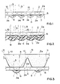
- Figur 1 Eine Schnittdarstellung des flächenhaften Strahlers, bei dem die als Vollform ausgebildeten Reflektoren unterhalb der transparenten Montageplatte angebracht sind.
- Figur 2 Eine Schnittdarstellung des flächenhaften Strahlers, bei dem die als Hohlform ausgebildeten Reflektoren unterhalb der transparenten Montageplatte angebracht sind.
- Figur 3 Eine Schnittdarstellung des flächenhaften Strahlers, bei dem die als Vollform ausgebildeten Reflektoren sowohl unterhalb als auch oberhalb der transparenten Montageplatte angeordnet sind.
- Figur 4 Eine Aufsicht auf die Montageplatte mit Leitbahnstruktur und Halbleiterkörpern.
- Das Herstellungsverfahren und die Wirkungsweise des erfindungsgemäßen flächenhaften Strahlers wird anhand des Ausführungsbeispiels in Figur 1 erläutert.
Auf die transparente Montageplatte 2, beispielsweise eine Glasplatte, werden mittels des bekannten photoli thographischen Verfahrens Leitbahnen 12 aufgebracht, die gemäß Figur 4 zur Kontaktierung und Zusammenschaltung der Halbleiterkörper 1 dienen.
Die Halbleiterkörper 1, die beispielsweise eine Ausdehnung von 250 µ x 250 µ besitzen, werden, vorzugsweise durch automatische Bestückung, auf die Montageplatte 2 aufgeklebt oder aufgelötet und durch Bonddrähte 7 mit den Leitbahnen 12 verbunden. Zur Herstellung der Reflektoren 3a wird eine Gießform, die beispielsweise die gleiche Form wie dem Formkörper 4 in Fig. 2 besitzen kann, mit einer Kunststoff-Vergußmasse, beispielsweise Siliconharz, Epoxidharz, Polyimid oder Polyphenylensulfid ausgegossen. Die transparente Montageplatte 2 mit Leitbahnstruktur 12 und den darauf befestigten Halbleiterkörpern 1 wird in die Vergußmasse so eingetaucht, daß sich jeder Halbleiterkörper 1 im Brennpunkt des vorzugsweise parabolischen Kunststoffkörpers 5 befindet. - Nach dem Härten der Vergußmasse und der Entformung durch die Entfernung der Gießform kann die Außenfläche 6 des Kunststoffkörpers zur Bildung der Reflektoren 3a mittels eines hochreflektierenden Materials, beispielsweise durch Aluminium oder Silber beschichtet werden. Durch die parabolische Form des Reflektors wird die gesamte reflektierte Strahlung 9 parallel gebündelt, so daß man die größtmögliche Lichtstärke erhält. Um eine gute Transmission der Strahlung 9 ohne Reflexion und Brechung an der Grenzfläche Reflektor/Montageplatte sicherzustellen, sollte der Kunststoffkörper 5 in etwa den gleichen Brechungsindex wie die transparente Montageplatte 2 aufweisen. Eine Glasplatte hat beispielsweise einen Brechungsindex von ca. 1,5.
Falls die Gießform z.B. aus Stabilitätsgründen oder als Schutz für die reflektierenden Flächen benötigt wird, wird sie nach dem Aushärten der Vergußmasse nicht entfernt. Die Innenseite der Gießform ist dann hochreflektierend ausgebildet, wozu sie vor dem Einbringen der Vergußmasse beispielsweise mit einem hochreflektierenden Material beschichtet werden kann.
Die direkte Strahlung 10 ist, im Gegensatz zur reflektierten Strahlung 9, nicht parallel gebündelt sondern isotrop verteilt, so daß sie nur in geringem Maße zu einer Erhöhung der Lichtstärke beiträgt. Daher wird die Kontaktfläche 8 auf der Rückseite des Halbleiterkörpers möglichst hochreflektierend ausgebildet. Dies bedingt, daß die in Richtung Montageplatte emittierte Strahlung 10 größtenteils reflektiert wird und zu der direkt in Richtung Reflektor emittierten und dort reflektierten Strahlung 9 und somit zur Gesamtemission beiträgt, so daß sich ein hoher Sammelwirkungsgrad ergibt. - In einer anderen Ausführungsform gemäß Figur 2, sind die Reflektoren 3b, vermöge eines Formkörpers 4, als Hohlform ausgebildet. Die Montage und Kontaktierung der Halbleiterkörper 1 auf der Montageplatte 2 wird genauso durchgeführt, wie dies anhand des Ausführungsbeispiels in Figur 1 beschrieben wurde. Um die Strahlungsauskopplung aus dem Lumineszenz-Halbleiterkörper 1 zu verbessern, werden die Halbleiterkörper mit einem Kunstharz 5a, der einen Brechungsindex von ca. 1,5 besitzt, betropft. Anschließend wird die Montageplatte 2 ohne Vergießen mit dem Formkörper 4 verbunden. Die Innenseite 6 des Formkörpers ist hochreflektierend und kann beispielsweise vor dem Zusammenschluß mit der Montageplatte mit einem hochreflektierenden Material beschichtet werden. Auch hier wird überwiegend nur die mittels des Reflektors 3b reflektierte Strahlung 9 ausgekoppelt.
- Bei einer weiteren Ausführungsform wird zunächst ein Strahler gemäß Figur 1 oder 2 als Vollform oder Hohlform ausgebildet und anschließend weitere Reflektoren 11, die mittels separater Gießformen oder Spritzformen hergestellt werden können, beispielsweise vermöge eines optischen Klebers auf der Oberseite 2a der Montageplatte angebracht. Diese zusätzlichen Reflektoren 11, in Figur 3 als Vollform dargestellt, besitzen die Form eines Parabelstumpfs und werden so auf die Oberseite 2a der Montageplatte geklebt, daß die Reflektoren 3a, 11 unterhalb und oberhalb der Montageplatte 2 zusammen ein parabolisches Profil ergeben.
- Bei dieser Ausführungsform wird sowohl ein Großteil der nach oben emittierten Strahlung 10 als auch die nach unten emittierte und reflektierte Strahlung 9 gebündelt, so daß die Lichtstärke und der Lichtnutzungsgrad ansteigt.
- In Figur 3 bestehen die Kunststoffkörper 5b der Reflektoren 11 oberhalb der Montageplatte vorzugsweise aus dem gleichen Material wie die Kunststoffkörper 5 der Reflektoren 3a unterhalb der Montageplatte. Die oberen Reflektoren 11 besitzen daher den gleichen Brechungsindex wie die transparente Montageplatte und ermöglichen somit eine gute Transmission der Strahlung ohne zusätzliche Reflexion oder Brechung an der Grenzfläche Montageplatte/Reflektor.
- In Figur 4 ist die Kontaktierung und Verdrahtung von Halbleiterkörpern 1 auf der Montageplatte 2 dargestellt. Je nach Erfordernissen und Spezifikation können mehrere Halbleiterkörper 1 auf der gesamten zu Verfügung stehenden Fläche der Montageplatte angebracht und zur Erhöhung der Betriebsspannung hintereinander geschaltet und/oder zur Erzielung der notwendigen Lichtstärke parallel geschaltet werden. Diese Zusammensschaltung ist dabei gemäß des vorgegebenen Layouts der Leitbahnstruktur 12 beliebig variierbar.
- Vorzugsweise werden die Halbleiterkörper 1 derart auf der Montageplatte 2 angeordnet, daß für bestimmte Anforderungen eine maximale Lichtstärke erzielt wird. Dazu können beispielsweise die Reflektoren 3 dicht aneinandergrenzen und so den auf der Montageplatte zur Verfügung stehenden Platz optimal ausnützen.
- Die Zahl der verwendeten Lumineszenzdioden, deren Verschaltung sowie die Wellenlänge der emittierten Strahlung kann dabei exakt nach den spezifischen Anforderungen vorgegeben werden und ohne weiteres auch in den infraroten Bereich, z. B. durch Bestückung mit GaAs-Dioden, verschoben werden.
Die verwendeten Lumineszenzdioden besitzen typischerweise eine Flußspannung von 2 V und eine zulässige Stromstärke von 50 mA, so daß beispielsweise für eine Betriebsspannung von 12 V ca. 5 - 6 Dioden hintereinander geschaltet werden müssen.
Der Lichtstrom einer Einzel-Lumineszenzdiode beträgt typischerweise 1 - 4 lm, die Lichtstärke ca. 1 - 3 cd; für eine Kfz-Bremsleuchte beispielsweise muß die Lichtstärke zwischen 40 cd und 100 cd liegen.
Um beispielsweise Rotlicht-emittierende Strahler zu erhalten, können GaAlAs-Heterostrukturdioden eingesetzt werden, deren maximale Emission bei 660 nm liegt. - Der erfindungsgemäße Strahler ist vielfältig einsetzbar; denkbar ist beispielsweise die Verwendung als Kfz-Leuchte, Signalleuchte, Begrenzungsleuchte oder in Ampeln.
Claims (15)
1) Flächenhafter Strahler, dadurch gekennzeichnet, daß eine transparente Montageplatte (2) mit Leitbahnstruktur (12) vorgesehen ist, auf der eine Vielzahl mit der Leitbahnstruktur (12) in Verbindung stehender Lumineszenz-Halbleiterkörper (1) in einer flächenhaften Verteilung befestigt ist, und daß jeder Halbleiterkörper (1) von einem Reflektor (3) umgeben ist, der den von dem Halbleiterkörper emittierten, auf den Reflektor (3) auftreffenden Lichtanteil durch die Montageplatte (2) reflektiert.
2) Flächenhafter Strahler nach Anspruch 1, dadurch gekennzeichnet, daß die Reflektoren (3) gleichmäßig verteilt auf der Montageplatte (2) angeordnet sind.
3) Flächenhafter Strahler nach Anspruch 1, dadurch gekennzeichnet, daß die Reflektoren (3) dicht aneinandergrenzend unter optimaler Ausnutzung der Fläche auf der Montageplatte (2) angeordnet sind.
4) Flächenhafter Strahler nach einem der vorangehenden Ansprüche, dadurch gekennzeichnet, daß jeder Halbleiterkörper (1) an der Unterseite (2b) der transparenten Montageplatte in einem Kunststoffkörper (5) eingebettet ist.
5) Flächenhafter Strahler nach Anspruch 4, dadurch gekennzeichnet, daß die Außenflächen (6) der Kunststoffkörper hochreflektierend ausgebildet sind.
6) Flächenhafter Strahler nach Anspruch 4, dadurch gekennzeichnet, daß die Kunststoffkörper (5) von einer Gießform umgeben sind, deren Innenseite die Reflektoren bildet.
7) Flächenhafter Strahler nach Anspruch 4-6, dadurch gekennzeichnet, daß der Brechungsindex des Kunststoffkörpers (5) in etwa so groß wie der Brechungsindex der transparenten Montageplatte (2) ist.
8) Flächenhafter Strahler nach Anspruch 1 oder 2, dadurch gekennzeichnet, daß die Halbleiterkörper (1) an der Unterseite (2b) der transparenten Montageplatte angebracht und von einem Formkörper (4) umgeben sind, dessen Innenseite (6) die Reflektoren (3b) bildet und sich zwischen Kunststoffkörper (5) und Formkörper (4) Luft befindet.
9) Flächenhafter Strahler nach einem der vorangehenden Ansprüche, dadurch gekennzeichnet, daß die Reflektoren (3a, 3b) parabolisch geformt sind, wobei jeweils ein Halbleiterkörper (1) im Brennpunkt eines Reflektors (3a, 3b) angeordnet ist.
10) Flächenhafter Strahler nach einem der vorangehenden Ansprüche, dadurch gekennzeichnet, daß an der Oberseite (2a) der transparenten Montageplatte zusätzliche Reflektoren (11) angebracht sind, die als Parabelstumpf ausgebildet sind und zusammen mit den Reflektoren (3a, 3b) an der Unterseite (2a) der Montageplatte die Struktur eines Paraboloids besitzen.
11) Flächenhafter Strahler nach Anspruch 10, dadurch gekennzeichnet, daß die zusätzlichen Reflektoren (11) an der Oberseite der transparenten Montageplatte als Kunststoffkörper (5b), deren Außenflächen hochreflektieren, ausgebildet sind.
12) Flächenhafter Strahler nach Anspruch 11, dadurch gekennzeichnet, daß der Brechungsindex des Kunststoffkörpers (5b) in etwa so groß wie der Brechungsindex der transparenten Montageplatte (2) ist.
13) Flächenhafter Strahler nach Anspruch 10, dadurch gekennzeichnet, daß die zusätzlichen Reflektoren an der Oberseite der transparenten Montageplatte mittels eines Formkörpers als Hohlform, deren Innenseite hochreflektierend ist, ausgebildet sind.
14) Flächenhafter Strahler nach einem der vorangehenden Ansprüche, dadurch gekennzeichnet, daß die Halbleiterkörper (1) mittels der Leitbahnstruktur (12) auf der transparenten Montageplatte (2) parallel- und/oder hintereinandergeschaltet werden.
15) Verwendung eines flächenhaften Strahlers nach einem der vorangehenden Ansprüche für Kfz-Leuchten, Signalleuchten, Begrenzungsleuchten oder Ampeln.
Applications Claiming Priority (2)
| Application Number | Priority Date | Filing Date | Title |
|---|---|---|---|
| DE3827083A DE3827083A1 (de) | 1988-08-10 | 1988-08-10 | Flaechenhafter strahler |
| DE3827083 | 1988-08-10 |
Publications (2)
| Publication Number | Publication Date |
|---|---|
| EP0354468A2 true EP0354468A2 (de) | 1990-02-14 |
| EP0354468A3 EP0354468A3 (de) | 1991-09-04 |
Family
ID=6360557
Family Applications (1)
| Application Number | Title | Priority Date | Filing Date |
|---|---|---|---|
| EP19890114320 Withdrawn EP0354468A3 (de) | 1988-08-10 | 1989-08-03 | Flächenhafter Strahler |
Country Status (4)
| Country | Link |
|---|---|
| US (1) | US4975814A (de) |
| EP (1) | EP0354468A3 (de) |
| JP (1) | JPH02119256A (de) |
| DE (1) | DE3827083A1 (de) |
Cited By (19)
| Publication number | Priority date | Publication date | Assignee | Title |
|---|---|---|---|---|
| EP0495685A1 (de) * | 1991-01-18 | 1992-07-22 | Nippon Sheet Glass Co. Ltd. | An der Heckscheibe eines Fahzeuges montierte Bremsleuchte |
| EP0534509A3 (en) * | 1991-09-25 | 1993-06-16 | Dhollandia, Naamloze Vennootschap | Signal light |
| US5241457A (en) * | 1991-01-18 | 1993-08-31 | Nippon Sheet Glass Co., Ltd. | Rear window stop lamp for motor vehicles |
| WO1997022147A3 (de) * | 1995-12-13 | 1997-08-14 | Loptique Ges Fuer Lichtsysteme | Leuchte mit geringem stromverbrauch |
| WO1999040364A1 (de) * | 1998-02-05 | 1999-08-12 | Zumtobel Staff Gmbh | Beleuchtungsanordnung |
| EP0921568A3 (de) * | 1997-11-25 | 2000-04-12 | Matsushita Electric Works, Ltd. | Leuchte mit lichtemittierenden Dioden |
| WO2002013231A3 (de) * | 2000-08-04 | 2002-06-20 | Osram Opto Semiconductors Gmbh | Strahlungsquelle und verfahren zur herstellung einer linsenform |
| US6809475B2 (en) | 2000-06-15 | 2004-10-26 | Lednium Pty Limited | Led lamp with light-emitting junctions arranged in a three-dimensional array |
| US7320632B2 (en) | 2000-06-15 | 2008-01-22 | Lednium Pty Limited | Method of producing a lamp |
| WO2008114200A1 (en) * | 2007-03-22 | 2008-09-25 | Koninklijke Philips Electronics N.V. | Flexible light source |
| EP1981147A1 (de) * | 2007-04-11 | 2008-10-15 | FELA Hitzinger GmbH | Beleuchtungseinheit mit einer transparenten Trägerplatte und daraufsitzender Leuchtdiode |
| US7704762B2 (en) | 2002-06-14 | 2010-04-27 | Lednium Technology Pty Limited | Lamp and method of producing a lamp |
| DE202010003621U1 (de) | 2010-03-15 | 2010-07-15 | Irlbacher Blickpunkt Glas Gmbh | Beleuchtungseinheit |
| EP1521313A3 (de) * | 2003-10-03 | 2010-12-29 | Philips Lumileds Lighting Company LLC | Integrierter Reflektor für eine Leuchtdioden-Montageplatte |
| DE102010002885A1 (de) | 2010-03-15 | 2011-09-15 | Irlbacher Blickpunkt Glas Gmbh | Beleuchtungseinheit mit organischer Leuchtdiode, deren Verwendung als Display sowie Verfahren zur Herstellung der Beleuchtungseinheit |
| DE102010002884A1 (de) | 2010-03-15 | 2011-09-15 | Irlbacher Blickpunkt Glas Gmbh | Beleuchtungseinheit, deren Verwendung als Display sowie Verfahren zur Herstellung der Beleuchtungseinheit |
| CN105782846A (zh) * | 2016-03-28 | 2016-07-20 | 广州维思车用部件有限公司 | Led车用照明装置、led车用前照灯以及led车用照明装置的发光方法 |
| EP3168530A1 (de) * | 2015-11-12 | 2017-05-17 | emdedesign GmbH | Leuchte umfassend eine anzahl led-leuchtmittel |
| WO2017187204A1 (en) * | 2016-04-29 | 2017-11-02 | Design Led Products Limited | Modular light panel |
Families Citing this family (77)
| Publication number | Priority date | Publication date | Assignee | Title |
|---|---|---|---|---|
| DE4208922C1 (en) * | 1992-03-19 | 1993-05-27 | Wustlich, Hans-Dieter | Flat display background illuminator - has plastics-sealed PCB housing which displays by reflection using diffusing glass in sealing material |
| US6590502B1 (en) | 1992-10-12 | 2003-07-08 | 911Ep, Inc. | Led warning signal light and movable support |
| DE9314709U1 (de) | 1993-09-29 | 1994-01-27 | Mayerhofer, Rosa, 73734 Esslingen | Flexible Leuchtbänder |
| US5469347A (en) * | 1994-02-07 | 1995-11-21 | Area Lighting Research, Inc. | Retro-fit illuminated sign module and method |
| DE19531295A1 (de) * | 1995-08-25 | 1997-02-27 | Reitter & Schefenacker Gmbh | Optikkörper für mindestens eine LED |
| US6095663A (en) * | 1997-07-02 | 2000-08-01 | Truck-Lite Co., Inc. | Combination clearance and marker light assembly |
| US5924788A (en) * | 1997-09-23 | 1999-07-20 | Teledyne Lighting And Display Products | Illuminating lens designed by extrinsic differential geometry |
| US6273596B1 (en) | 1997-09-23 | 2001-08-14 | Teledyne Lighting And Display Products, Inc. | Illuminating lens designed by extrinsic differential geometry |
| US6113248A (en) * | 1997-10-20 | 2000-09-05 | The Standard Products Company | Automated system for manufacturing an LED light strip having an integrally formed connector |
| GB2330679B (en) | 1997-10-21 | 2002-04-24 | 911 Emergency Products Inc | Warning signal light |
| DE29805743U1 (de) * | 1998-03-28 | 1998-12-24 | Büchner, Thomas, 86459 Gessertshausen | Auflichtbeleuchtungsvorrichtung |
| DE29809093U1 (de) | 1998-05-22 | 1998-07-16 | Rosa, Christoph, 60486 Frankfurt | Lichtmatte |
| US5960942A (en) * | 1998-07-08 | 1999-10-05 | Ericsson, Inc. | Thin profile keypad with integrated LEDs |
| WO2000049332A1 (en) * | 1999-02-16 | 2000-08-24 | Tokheim Corporation | Led backlighting apparatus for use in fuel dispensers |
| US6462669B1 (en) | 1999-04-06 | 2002-10-08 | E. P . Survivors Llc | Replaceable LED modules |
| US6614359B2 (en) | 1999-04-06 | 2003-09-02 | 911 Emergency Products, Inc. | Replacement led lamp assembly and modulated power intensity for light source |
| US6705745B1 (en) | 1999-06-08 | 2004-03-16 | 911Ep, Inc. | Rotational led reflector |
| WO2000074972A1 (en) | 1999-06-08 | 2000-12-14 | 911 Emergency Products, Inc. | Led light stick assembly |
| US6700502B1 (en) | 1999-06-08 | 2004-03-02 | 911Ep, Inc. | Strip LED light assembly for motor vehicle |
| EP1119058A4 (de) * | 1999-07-29 | 2006-08-23 | Citizen Electronics | Lichtemittierende diode |
| US6367949B1 (en) | 1999-08-04 | 2002-04-09 | 911 Emergency Products, Inc. | Par 36 LED utility lamp |
| US6443594B1 (en) * | 2000-03-31 | 2002-09-03 | Koninklijke Philips Electronics N.V. | One-piece lens arrays for collimating and focusing light and led light generators using same |
| IT1320547B1 (it) * | 2000-07-21 | 2003-12-10 | Fiat Ricerche | Dispositivo di illuminazione, particolarmente proiettore o fanale diautoveicolo con distribuzione a matrice di sorgenti luminose |
| GB2366610A (en) * | 2000-09-06 | 2002-03-13 | Mark Shaffer | Electroluminscent lamp |
| CN1259732C (zh) * | 2000-09-29 | 2006-06-14 | 欧姆龙株式会社 | 光学器件及其应用 |
| US7439847B2 (en) * | 2002-08-23 | 2008-10-21 | John C. Pederson | Intelligent observation and identification database system |
| WO2002041276A2 (en) | 2000-11-15 | 2002-05-23 | Snowy Village, Inc. | Led warning light and communication system |
| US8188878B2 (en) | 2000-11-15 | 2012-05-29 | Federal Law Enforcement Development Services, Inc. | LED light communication system |
| DE10207431B4 (de) * | 2002-02-21 | 2009-12-31 | Bayerische Motoren Werke Aktiengesellschaft | Mehrfunktions-Signalleuchte eines Kraftfahrzeugs |
| DE10255015B4 (de) * | 2002-11-25 | 2008-09-25 | Daimler Ag | Breitbandige Beleuchtungseinrichtung |
| US7175304B2 (en) * | 2003-01-30 | 2007-02-13 | Touchsensor Technologies, Llc | Integrated low profile display |
| EP1590831A2 (de) * | 2003-02-05 | 2005-11-02 | Acol Technologies S.A. | Lichtemittierende bauelemente |
| CA2518625A1 (en) * | 2003-03-12 | 2004-09-23 | Lednium Pty. Ltd. | A lamp and a process for producing a lamp |
| TW578310B (en) * | 2003-04-02 | 2004-03-01 | Au Optronics Corp | Low temperature poly silicon thin film transistor and method of forming poly silicon layer of the same |
| JP2004349628A (ja) * | 2003-05-26 | 2004-12-09 | Sharp Corp | 半導体発光装置及びそれを用いた撮影用照明装置 |
| US20050001562A1 (en) * | 2003-07-02 | 2005-01-06 | 911Ep, Inc. | LED compensation circuit |
| US7281818B2 (en) * | 2003-12-11 | 2007-10-16 | Dialight Corporation | Light reflector device for light emitting diode (LED) array |
| WO2005070456A2 (en) * | 2004-01-09 | 2005-08-04 | Millennium Pharmaceuticals, Inc. | Diagnosing and treating female reproductive tract or chilhood cancer with pmsa antibodies |
| GB0501309D0 (en) * | 2005-01-24 | 2005-03-02 | Lumidrives Ltd | Sealed light fixture |
| TWI319504B (en) * | 2005-06-28 | 2010-01-11 | Chi Mei Optoelectronics Corp | Planar light source device and fabricating method thereof and liquid crystal display with the same |
| NL1030161C2 (nl) | 2005-10-11 | 2007-04-12 | Matthijs Dirk Meulenbelt | Presentatie-inrichting. |
| KR20090079929A (ko) * | 2006-10-10 | 2009-07-22 | 코닌클리즈케 필립스 일렉트로닉스 엔.브이. | 박형 조명 장치, 디스플레이 장치 및 발광 장치 |
| US9100124B2 (en) | 2007-05-24 | 2015-08-04 | Federal Law Enforcement Development Services, Inc. | LED Light Fixture |
| US9258864B2 (en) | 2007-05-24 | 2016-02-09 | Federal Law Enforcement Development Services, Inc. | LED light control and management system |
| US9414458B2 (en) | 2007-05-24 | 2016-08-09 | Federal Law Enforcement Development Services, Inc. | LED light control assembly and system |
| US9294198B2 (en) | 2007-05-24 | 2016-03-22 | Federal Law Enforcement Development Services, Inc. | Pulsed light communication key |
| US11265082B2 (en) | 2007-05-24 | 2022-03-01 | Federal Law Enforcement Development Services, Inc. | LED light control assembly and system |
| WO2008148039A1 (en) | 2007-05-24 | 2008-12-04 | Federal Law Enforcement Development Services, Inc. | Led light communication system |
| US9455783B2 (en) | 2013-05-06 | 2016-09-27 | Federal Law Enforcement Development Services, Inc. | Network security and variable pulse wave form with continuous communication |
| DE102007025749A1 (de) * | 2007-06-01 | 2008-12-11 | Wacker Chemie Ag | Leuchtkörper-Silicon-Formteil |
| TWI331243B (en) * | 2007-08-20 | 2010-10-01 | Au Optronics Corp | Backlight module and scattering module for same |
| DE102008006229B4 (de) | 2008-01-25 | 2013-08-29 | We-Ef Leuchten Gmbh & Co. Kg | Straßenbeleuchtungseinrichtung |
| CN101566309A (zh) * | 2008-04-23 | 2009-10-28 | 富准精密工业(深圳)有限公司 | 发光二极管照明装置 |
| US20090268461A1 (en) * | 2008-04-28 | 2009-10-29 | Deak David G | Photon energy conversion structure |
| JP2010135747A (ja) * | 2008-11-07 | 2010-06-17 | Toshiba Lighting & Technology Corp | 発光モジュールおよび照明装置 |
| US8890773B1 (en) | 2009-04-01 | 2014-11-18 | Federal Law Enforcement Development Services, Inc. | Visible light transceiver glasses |
| WO2011033433A1 (en) * | 2009-09-17 | 2011-03-24 | Koninklijke Philips Electronics N.V. | Light-source module and light-emitting device |
| FR2956468B1 (fr) | 2010-02-15 | 2015-07-10 | Valeo Vision | Dispositif optique, notamment pour vehicule automobile |
| US8543505B2 (en) | 2011-01-14 | 2013-09-24 | Federal Law Enforcement Development Services, Inc. | Method of providing lumens and tracking of lumen consumption |
| US10103297B2 (en) | 2012-12-10 | 2018-10-16 | Daktronics, Inc. | Encapsulation of light-emitting elements on a display module |
| TWI622189B (zh) * | 2013-02-08 | 2018-04-21 | 晶元光電股份有限公司 | 發光二極體元件 |
| US9265112B2 (en) | 2013-03-13 | 2016-02-16 | Federal Law Enforcement Development Services, Inc. | LED light control and management system |
| MX344619B (es) * | 2013-03-15 | 2017-01-03 | Morgan Solar Inc | Panel de luz, montaje optico con interfaz mejorada y panel de luz con tolerancias mejoradas de fabricacion. |
| US9595627B2 (en) | 2013-03-15 | 2017-03-14 | John Paul Morgan | Photovoltaic panel |
| US9960303B2 (en) | 2013-03-15 | 2018-05-01 | Morgan Solar Inc. | Sunlight concentrating and harvesting device |
| US9714756B2 (en) * | 2013-03-15 | 2017-07-25 | Morgan Solar Inc. | Illumination device |
| US20150198941A1 (en) | 2014-01-15 | 2015-07-16 | John C. Pederson | Cyber Life Electronic Networking and Commerce Operating Exchange |
| US20170046950A1 (en) | 2015-08-11 | 2017-02-16 | Federal Law Enforcement Development Services, Inc. | Function disabler device and system |
| AU2017269239A1 (en) | 2016-05-21 | 2019-01-03 | JST Performance, LLC | Method and apparatus for vehicular light fixtures |
| US10393348B2 (en) | 2017-02-24 | 2019-08-27 | Glint Photonics, Inc. | Configurable luminaire |
| CN107092132A (zh) * | 2017-05-23 | 2017-08-25 | 张家港康得新光电材料有限公司 | 一种直下式led光源组件、背光模组及显示面板 |
| CN107092133A (zh) * | 2017-05-23 | 2017-08-25 | 张家港康得新光电材料有限公司 | 一种直下式led光源组件、背光模组及显示面板 |
| CN107390425A (zh) * | 2017-05-23 | 2017-11-24 | 张家港康得新光电材料有限公司 | 一种直下式led光源模块、背光模组及显示面板 |
| CN111105726A (zh) * | 2020-01-14 | 2020-05-05 | 深圳市生辉煌电子有限公司 | 一种可视角度的led显示屏 |
| CN111308783A (zh) * | 2020-03-25 | 2020-06-19 | 深圳市隆利科技股份有限公司 | Led背光装置及显示设备 |
| US20220196224A1 (en) | 2020-12-20 | 2022-06-23 | Glint Photonics, Inc. | Beam-steering reflective optics |
| CN115728992A (zh) * | 2022-11-24 | 2023-03-03 | 深圳创维-Rgb电子有限公司 | 背光模组及显示装置 |
Family Cites Families (22)
| Publication number | Priority date | Publication date | Assignee | Title |
|---|---|---|---|---|
| US3821775A (en) * | 1971-09-23 | 1974-06-28 | Spectronics Inc | Edge emission gaas light emitter structure |
| SE385419B (sv) * | 1974-03-22 | 1976-06-28 | Asea Ab | Lysdiodanordning for utsendande av stralning i en forutbestemd riktning |
| DE2757869A1 (de) * | 1976-12-27 | 1978-07-27 | Monsanto Co | In felder aufgeteilte anzeigeeinrichtung mit lichtaussendenden dioden |
| DE2732780A1 (de) * | 1977-07-20 | 1979-02-08 | Schraudner Josef | Kraftfahrzeug-sicherheitsbeleuchtung und sicherheitsbeleuchtung in beleuchtungskoerpern |
| DE2814877A1 (de) * | 1978-04-06 | 1979-10-11 | Me Meerestechnik Elektronik Gm | Sicherheitsleuchte |
| US4271408A (en) * | 1978-10-17 | 1981-06-02 | Stanley Electric Co., Ltd. | Colored-light emitting display |
| DE2934140A1 (de) * | 1979-08-23 | 1981-03-26 | Siemens AG, 1000 Berlin und 8000 München | Lichtquelle mit einstellbarer intensitaetsverteilung und hoher leuchtdichte |
| US4467193A (en) * | 1981-09-14 | 1984-08-21 | Carroll Manufacturing Corporation | Parabolic light emitter and detector unit |
| DE3148843C2 (de) * | 1981-12-10 | 1986-01-02 | Telefunken electronic GmbH, 7100 Heilbronn | Mehrfach-Leuchtdiodenanordnung |
| FR2520934B1 (fr) * | 1982-01-29 | 1985-06-07 | Radiotechnique Compelec | Dispositif semi-conducteur emetteur de lumiere a multicristaux |
| DE3230975A1 (de) * | 1982-08-20 | 1984-02-23 | Robert Bosch Gmbh, 7000 Stuttgart | Kraftfahrzeugleuchte aus leuchtdioden oder leuchtdiodenchips |
| US4439818A (en) * | 1983-02-25 | 1984-03-27 | Scheib Joseph J | Flexible light display with evenly distributed illumination |
| DE3315785A1 (de) * | 1983-04-30 | 1984-11-08 | Robert Bosch Gmbh, 7000 Stuttgart | Kraftfahrzeugleuchte |
| DE8313500U1 (de) * | 1983-05-06 | 1983-09-15 | knitter-switch, elektrotechnische Erzeugnisse, Knitter & Co KG, 8011 Baldham | Leuchtdiodenanordnung |
| FR2547087B1 (fr) * | 1983-05-30 | 1985-07-12 | Radiotechnique Compelec | Element de panneau d'affichage a cristaux semi-conducteurs et panneau comportant ledit element |
| JPS6063970A (ja) * | 1983-09-17 | 1985-04-12 | Fanuc Ltd | 平行光線を放射する発光ダイオ−ド |
| JPS612620U (ja) * | 1984-06-11 | 1986-01-09 | 東芝ライテック株式会社 | 発光ダイオ−ドアレイ |
| DE3438154C2 (de) * | 1984-10-18 | 1994-09-15 | Teves Gmbh Alfred | Rückleuchte für Kraftfahrzeuge |
| US4733335A (en) * | 1984-12-28 | 1988-03-22 | Koito Manufacturing Co., Ltd. | Vehicular lamp |
| DD241155A1 (de) * | 1985-09-18 | 1986-11-26 | Werk Fernsehelektronik Veb | Miniatur - led |
| FR2601486B1 (fr) * | 1986-07-11 | 1989-04-14 | Signal Vision Sa | Procede de fabrication d'une plaque eclairante a diodes electroluminescentes et feu de signalisation obtenu par ce procede |
| WO1989005524A1 (fr) * | 1987-11-30 | 1989-06-15 | Iwasaki Electric Co., Ltd | Source lumineuse plane a diode electroluminescente |
-
1988
- 1988-08-10 DE DE3827083A patent/DE3827083A1/de not_active Ceased
-
1989
- 1989-08-03 EP EP19890114320 patent/EP0354468A3/de not_active Withdrawn
- 1989-08-08 US US07/390,817 patent/US4975814A/en not_active Expired - Fee Related
- 1989-08-08 JP JP1204005A patent/JPH02119256A/ja active Pending
Cited By (27)
| Publication number | Priority date | Publication date | Assignee | Title |
|---|---|---|---|---|
| US5241457A (en) * | 1991-01-18 | 1993-08-31 | Nippon Sheet Glass Co., Ltd. | Rear window stop lamp for motor vehicles |
| EP0495685A1 (de) * | 1991-01-18 | 1992-07-22 | Nippon Sheet Glass Co. Ltd. | An der Heckscheibe eines Fahzeuges montierte Bremsleuchte |
| EP0534509A3 (en) * | 1991-09-25 | 1993-06-16 | Dhollandia, Naamloze Vennootschap | Signal light |
| WO1997022147A3 (de) * | 1995-12-13 | 1997-08-14 | Loptique Ges Fuer Lichtsysteme | Leuchte mit geringem stromverbrauch |
| EP0921568A3 (de) * | 1997-11-25 | 2000-04-12 | Matsushita Electric Works, Ltd. | Leuchte mit lichtemittierenden Dioden |
| US6639350B1 (en) | 1998-02-05 | 2003-10-28 | Zumiobel Staff Gmbh | Illumination arrangement |
| WO1999040364A1 (de) * | 1998-02-05 | 1999-08-12 | Zumtobel Staff Gmbh | Beleuchtungsanordnung |
| AU740362B2 (en) * | 1998-02-05 | 2001-11-01 | Zumtobel Staff Gmbh | Illumination arrangement |
| US7352127B2 (en) | 2000-06-15 | 2008-04-01 | Lednium Pty Limited | LED lamp with light-emitting junction arranged in three-dimensional array |
| US7320632B2 (en) | 2000-06-15 | 2008-01-22 | Lednium Pty Limited | Method of producing a lamp |
| US6809475B2 (en) | 2000-06-15 | 2004-10-26 | Lednium Pty Limited | Led lamp with light-emitting junctions arranged in a three-dimensional array |
| US7262437B2 (en) | 2000-08-04 | 2007-08-28 | Osram Opto Semiconductors Gmbh | Radiation source and method for producing a lens mould |
| WO2002013231A3 (de) * | 2000-08-04 | 2002-06-20 | Osram Opto Semiconductors Gmbh | Strahlungsquelle und verfahren zur herstellung einer linsenform |
| CN100517706C (zh) * | 2000-08-04 | 2009-07-22 | 奥斯兰姆奥普托半导体有限责任公司 | 辐射源和用于制造透镜模的方法 |
| US7704762B2 (en) | 2002-06-14 | 2010-04-27 | Lednium Technology Pty Limited | Lamp and method of producing a lamp |
| EP1521313A3 (de) * | 2003-10-03 | 2010-12-29 | Philips Lumileds Lighting Company LLC | Integrierter Reflektor für eine Leuchtdioden-Montageplatte |
| WO2008114200A1 (en) * | 2007-03-22 | 2008-09-25 | Koninklijke Philips Electronics N.V. | Flexible light source |
| DE102007017335C5 (de) * | 2007-04-11 | 2017-04-27 | FELA GmbH | Beleuchtungseinheit mit einer transparenten Trägerplatte und daraufsitzender Leuchtdiode |
| EP1981147A1 (de) * | 2007-04-11 | 2008-10-15 | FELA Hitzinger GmbH | Beleuchtungseinheit mit einer transparenten Trägerplatte und daraufsitzender Leuchtdiode |
| DE202010003621U1 (de) | 2010-03-15 | 2010-07-15 | Irlbacher Blickpunkt Glas Gmbh | Beleuchtungseinheit |
| DE102010002884A1 (de) | 2010-03-15 | 2011-09-15 | Irlbacher Blickpunkt Glas Gmbh | Beleuchtungseinheit, deren Verwendung als Display sowie Verfahren zur Herstellung der Beleuchtungseinheit |
| EP2375396A1 (de) | 2010-03-15 | 2011-10-12 | Irlbacher Blickpunkt Glas GmbH | Beleuchtungseinheit, deren Verwendung sowie Verfahren zur Herstellung der Beleuchtungseinheit |
| DE102010002885A1 (de) | 2010-03-15 | 2011-09-15 | Irlbacher Blickpunkt Glas Gmbh | Beleuchtungseinheit mit organischer Leuchtdiode, deren Verwendung als Display sowie Verfahren zur Herstellung der Beleuchtungseinheit |
| EP3168530A1 (de) * | 2015-11-12 | 2017-05-17 | emdedesign GmbH | Leuchte umfassend eine anzahl led-leuchtmittel |
| CN105782846A (zh) * | 2016-03-28 | 2016-07-20 | 广州维思车用部件有限公司 | Led车用照明装置、led车用前照灯以及led车用照明装置的发光方法 |
| WO2017187204A1 (en) * | 2016-04-29 | 2017-11-02 | Design Led Products Limited | Modular light panel |
| US10939836B2 (en) | 2016-04-29 | 2021-03-09 | Design Led Products Limited | Modular light panel having light sources and environemental sensor units |
Also Published As
| Publication number | Publication date |
|---|---|
| EP0354468A3 (de) | 1991-09-04 |
| US4975814A (en) | 1990-12-04 |
| JPH02119256A (ja) | 1990-05-07 |
| DE3827083A1 (de) | 1990-02-15 |
Similar Documents
| Publication | Publication Date | Title |
|---|---|---|
| EP0354468A2 (de) | Flächenhafter Strahler | |
| EP0364806B1 (de) | Flächenhafter Strahler | |
| DE102005030128B4 (de) | Lichtemittierende Vorrichtung und Beleuchtungsvorrichtung | |
| DE69530221T2 (de) | Anordnungen von optoelektronischen bauelementen und herstellungsverfahren | |
| DE102005033709B4 (de) | Lichtemittierendes Modul | |
| DE10159695B4 (de) | Einen hohen Lichtstrom emittierende Diode mit einer Licht emittierenden Diode vom Flip-Chip-Typ mit einem transparenten Substrat | |
| DE102010028407B4 (de) | Optoelektronisches Bauelement und Verfahren zum Herstellen eines optoelektronischen Bauelements | |
| DE69838597T2 (de) | Lichtemittierende Halbleitervorrichtung und Herstellungsverfahren | |
| EP1352432B1 (de) | Lumineszenzdiode und verfahren zu deren herstellung | |
| DE19746893B4 (de) | Optoelektronisches Bauelement mit Wärmesenke im Sockelteil und Verfahren zur Herstellung | |
| EP2317213B1 (de) | Leuchtdiodenmodul einer Kraftfahrzeugbeleuchtungseinrichtung und Kraftfahrzeugbeleuchtungseinrichtung | |
| DE102007044684B4 (de) | Kompakte Hochintensitäts LED basierte Lichtquelle und Verfahren zum Herstellen derselben | |
| DE10216008A1 (de) | LED-Lampe | |
| EP1805815A2 (de) | Beleuchtungseinrichtung, kfz-scheinwerfer und verfahren zur herstellung einer beleuctungseinrichtung | |
| CN1348608A (zh) | 具有透镜的led光源 | |
| DE112007000773T5 (de) | Licht emittierende Vorrichtung | |
| EP1299910A1 (de) | Led-modul, verfahren zu dessen herstellung und dessen verwendung | |
| DE102005020908A1 (de) | Beleuchtungsvorrichtung | |
| DE19831607B4 (de) | Lineares Beleuchtungsbauelement und Bildlesevorrichtung, welche dieses verwendet | |
| WO2013110540A1 (de) | Leuchte und verfahren zur herstellung einer leuchte | |
| EP1854153A1 (de) | Led-array | |
| DE10129950A1 (de) | Leuchte für Fahrzeuge und Verfahren zur Herstellung derselben | |
| DE102017222649A1 (de) | Lichtmodul, anordnung, scheinwerfer und verfahren | |
| DE102005037888A1 (de) | Leuchtdiodengehäuse und Verfahren zu dessen Herstellung | |
| EP1217664B1 (de) | Halbleiter-Leuchteinheit und Verfahren zur Herstellung derselben |
Legal Events
| Date | Code | Title | Description |
|---|---|---|---|
| PUAI | Public reference made under article 153(3) epc to a published international application that has entered the european phase |
Free format text: ORIGINAL CODE: 0009012 |
|
| AK | Designated contracting states |
Kind code of ref document: A2 Designated state(s): DE ES FR GB IT |
|
| PUAL | Search report despatched |
Free format text: ORIGINAL CODE: 0009013 |
|
| RHK1 | Main classification (correction) |
Ipc: H01L 33/00 |
|
| AK | Designated contracting states |
Kind code of ref document: A3 Designated state(s): DE ES FR GB IT |
|
| STAA | Information on the status of an ep patent application or granted ep patent |
Free format text: STATUS: THE APPLICATION IS DEEMED TO BE WITHDRAWN |
|
| 18D | Application deemed to be withdrawn |
Effective date: 19910903 |