EP0354561B1 - Verfahren und Gerät zum automatischen Fahren - Google Patents
Verfahren und Gerät zum automatischen Fahren Download PDFInfo
- Publication number
- EP0354561B1 EP0354561B1 EP89114747A EP89114747A EP0354561B1 EP 0354561 B1 EP0354561 B1 EP 0354561B1 EP 89114747 A EP89114747 A EP 89114747A EP 89114747 A EP89114747 A EP 89114747A EP 0354561 B1 EP0354561 B1 EP 0354561B1
- Authority
- EP
- European Patent Office
- Prior art keywords
- vehicle
- course
- target course
- travelling
- steering
- Prior art date
- Legal status (The legal status is an assumption and is not a legal conclusion. Google has not performed a legal analysis and makes no representation as to the accuracy of the status listed.)
- Expired - Lifetime
Links
- 238000000034 method Methods 0.000 title description 3
- 230000007423 decrease Effects 0.000 claims description 5
- 238000012937 correction Methods 0.000 claims description 2
- 230000015654 memory Effects 0.000 description 22
- 238000012545 processing Methods 0.000 description 8
- 238000006243 chemical reaction Methods 0.000 description 5
- 230000009466 transformation Effects 0.000 description 4
- 238000010586 diagram Methods 0.000 description 3
- 230000004044 response Effects 0.000 description 3
- 230000009471 action Effects 0.000 description 2
- 238000001514 detection method Methods 0.000 description 2
- 230000004069 differentiation Effects 0.000 description 2
- 238000009434 installation Methods 0.000 description 2
- 230000008569 process Effects 0.000 description 2
- 230000001133 acceleration Effects 0.000 description 1
- 230000008859 change Effects 0.000 description 1
- 239000004020 conductor Substances 0.000 description 1
- 230000003247 decreasing effect Effects 0.000 description 1
- 230000001419 dependent effect Effects 0.000 description 1
- 230000000694 effects Effects 0.000 description 1
- 230000007246 mechanism Effects 0.000 description 1
- 230000000007 visual effect Effects 0.000 description 1
Images



Classifications
-
- G—PHYSICS
- G05—CONTROLLING; REGULATING
- G05D—SYSTEMS FOR CONTROLLING OR REGULATING NON-ELECTRIC VARIABLES
- G05D1/00—Control of position, course, altitude or attitude of land, water, air or space vehicles, e.g. using automatic pilots
- G05D1/02—Control of position or course in two dimensions
- G05D1/021—Control of position or course in two dimensions specially adapted to land vehicles
- G05D1/0231—Control of position or course in two dimensions specially adapted to land vehicles using optical position detecting means
- G05D1/0246—Control of position or course in two dimensions specially adapted to land vehicles using optical position detecting means using a video camera in combination with image processing means
-
- G—PHYSICS
- G05—CONTROLLING; REGULATING
- G05D—SYSTEMS FOR CONTROLLING OR REGULATING NON-ELECTRIC VARIABLES
- G05D1/00—Control of position, course, altitude or attitude of land, water, air or space vehicles, e.g. using automatic pilots
- G05D1/02—Control of position or course in two dimensions
- G05D1/021—Control of position or course in two dimensions specially adapted to land vehicles
- G05D1/0212—Control of position or course in two dimensions specially adapted to land vehicles with means for defining a desired trajectory
-
- G—PHYSICS
- G05—CONTROLLING; REGULATING
- G05D—SYSTEMS FOR CONTROLLING OR REGULATING NON-ELECTRIC VARIABLES
- G05D1/00—Control of position, course, altitude or attitude of land, water, air or space vehicles, e.g. using automatic pilots
- G05D1/02—Control of position or course in two dimensions
- G05D1/021—Control of position or course in two dimensions specially adapted to land vehicles
- G05D1/0268—Control of position or course in two dimensions specially adapted to land vehicles using internal positioning means
- G05D1/0274—Control of position or course in two dimensions specially adapted to land vehicles using internal positioning means using mapping information stored in a memory device
-
- B—PERFORMING OPERATIONS; TRANSPORTING
- B60—VEHICLES IN GENERAL
- B60T—VEHICLE BRAKE CONTROL SYSTEMS OR PARTS THEREOF; BRAKE CONTROL SYSTEMS OR PARTS THEREOF, IN GENERAL; ARRANGEMENT OF BRAKING ELEMENTS ON VEHICLES IN GENERAL; PORTABLE DEVICES FOR PREVENTING UNWANTED MOVEMENT OF VEHICLES; VEHICLE MODIFICATIONS TO FACILITATE COOLING OF BRAKES
- B60T2201/00—Particular use of vehicle brake systems; Special systems using also the brakes; Special software modules within the brake system controller
- B60T2201/08—Lane monitoring; Lane Keeping Systems
-
- B—PERFORMING OPERATIONS; TRANSPORTING
- B60—VEHICLES IN GENERAL
- B60T—VEHICLE BRAKE CONTROL SYSTEMS OR PARTS THEREOF; BRAKE CONTROL SYSTEMS OR PARTS THEREOF, IN GENERAL; ARRANGEMENT OF BRAKING ELEMENTS ON VEHICLES IN GENERAL; PORTABLE DEVICES FOR PREVENTING UNWANTED MOVEMENT OF VEHICLES; VEHICLE MODIFICATIONS TO FACILITATE COOLING OF BRAKES
- B60T2201/00—Particular use of vehicle brake systems; Special systems using also the brakes; Special software modules within the brake system controller
- B60T2201/08—Lane monitoring; Lane Keeping Systems
- B60T2201/087—Lane monitoring; Lane Keeping Systems using active steering actuation
-
- G—PHYSICS
- G05—CONTROLLING; REGULATING
- G05D—SYSTEMS FOR CONTROLLING OR REGULATING NON-ELECTRIC VARIABLES
- G05D1/00—Control of position, course, altitude or attitude of land, water, air or space vehicles, e.g. using automatic pilots
- G05D1/02—Control of position or course in two dimensions
- G05D1/021—Control of position or course in two dimensions specially adapted to land vehicles
- G05D1/0268—Control of position or course in two dimensions specially adapted to land vehicles using internal positioning means
- G05D1/0272—Control of position or course in two dimensions specially adapted to land vehicles using internal positioning means comprising means for registering the travel distance, e.g. revolutions of wheels
Definitions
- the present invention relates to an automatic travelling apparatus according to the preamble part of claim 1.
- the automatic travelling apparatus decomposes the path which the vehicle has to follow into a set of short, straight line segments. More particularly, the simulator computes a tentative course beginning at the simulated current position, sloping in the direction of the heading of the simulated vehicule and terminating 13 meter along the target course, in this case the road center line of a road network model.
- the computed tentative course is converted in a sequence of steering commands relating to the robot arm which carries a CCD camera (as vehicle) over said road network model, whereby a curved path is decomposed in a set of short straight line segments.
- a vehicle steering control system for steering either off (or both) front and rear wheel pairs of a controlled vehicle is known.
- desired values of yaw rate and lateral acceleration corresponding to the steering wheel angle (sensed by a steering wheel angle sensor) and the vehicle speed (sensed by a vehicle speed sensor) are calculated by using at least one desired mathematical vehicle model.
- an automatic travelling system in the form of an automatic power lawn mower is known being equipped with an image pick-up device such as a video camera. While continuously taking images of the lawn area ahead the lawn mower, these images are treated to enhance the difference of shade between the finished and unfished areas, thereby permitting exact detection of the boundary between the finished and unfinished areas. The mower is steered to travel along the boundary thus detected. Accordingly, this automatic travelling system is capable of determining a course to follow, but this automatic travelling system is essentially the same as the automatic travelling system described above in respect of the vehicle which follows a single guideline laid on a road.
- Estimation of the steering amount on the basis of the instantaneous running conditions and comparison of the presumed course determined by the instantaneous running conditions with the target course guarantee that the vehicle follows the target course smoothly for a wide range of instantaneous running conditions and target course curvatures. If the vehicle is not on the target course, it is caused to get on the target course and remain there afterwards.
- the comparison of the presumed course with the target course corresponds in effect to a sort of closed-loop control which provides a very high reliability in smoothly following the target course as exactly as possible.
- an automatic travelling apparatus comprises: an image pickup device such as video cameras 11 and 12 attached to a vehicle for continuously picking up subsequent images of ground ahead of the vehicle; means 2 for processing the images taken by the video cameras and determining a permissible travelling area such as a road in the direction in which the vehicle is to travel; means 3 for setting a target course in the permissible travelling area thus determined; means 4 for determining the instantaneous running condition of the vehicle on the basis of an output signal from a speed sensor 5 representing the running speed "v" of the vehicle, an output signal from a yaw rate sensor 6 representing the yaw rate or angular velocity increment in yawing direction, and an output signal from a tire angle sensor 7 representing the tire angle ⁇ which varies with the steering of the vehicle, and for estimating, on the basis of the instantaneous running condition, a steering amount to permit the vehicle to follow the target course; and means 8 (and a steerage drive 9) for steering the vehicle with reference to the steering amount.
- an image pickup device such as video cameras 11
- a computer aided control is used in place of means 2, 3 and 4, and means 8 can be included in the computer aided control, if occasions demand.
- Fig.2 shows the structure of the permissible travelling area determining means 2 as comprising: first stage including image input 22, buffer memories 231, 232, memory selector 27 and decoder 28; second stage including image processor 24 connected to memory selector 27 of the first stage via D-bus (high-speed data bus); third stage including memory selector 27, image memories 251, 252 and 253 and decoder 28; fourth stage including memory selector 27, image memories 261, 262 and 263 and decoder 28, memory selectors 25 and 26 of the third and fourth stages being connected to the image processor 24 via D-bus; first and second CPUs 211 and 212 both connected to decoders 28 of the first, third and fourth stages via S-bus (system bus) and connected to decoders 28 of the third and fourth stages via M-bus (high-speed memory access bus).
- a series of image signals each representing a single image are supplied from the video cameras 11, 12 to the image input of the first stage, and then these image signals are stored alternately in the buffer memories 231 and 232 under the control of the CPUs 211 and 212. Then, these image informations are shifted to the image processor 24 one after another, where they are subjected to image processing, thereby detecting road edges in images if any, and determining a permissible travelling area as later described in detail.
- the image informations pertaining to permissible travelling areas are supplied to a group of image memories 251, 252 and 253 or a group of image memories 261, 262 and 263. Then, the contents of these memories are renewed by these latest image informations pertaining to permissible travelling areas.
- Parallel installations of two CPUs 211 and 212 and two buffer memories 231 and 232 permit alternate retrieval or storage of image informations to either buffer memory, as for example follows: while first image informations stored in the buffer memory 231 are read under the control of the CPU 211, subsequent image informations are stored in the buffer memory 232 under the control of the CPU 212. Thus, the inputting of image informations can be carried out on the real time basis.
- each image supplied from the video cameras will be subjected to differentiation process, and road edges if any, will be detected.
- an automatic threshold setting circuit in the permissible travelling area detection means 2 sets a threshold value in consideration of road the degree of shade of the image information just processed.
- the road edge image will be subjected to binary transformation.
- the images may be subjected to binary transformation, and then the binary data may be subjected to differentiation.
- binary transformation poly-digitization may be performed to express some shade details of image.
- Digitalized image information will be subjected to the Hough conversion to convert the X-Y linear coordinates to the corresponding ⁇ - ⁇ point coordinates, thus eliminating isolated points and plotting to provide a continuous road edge image as shown in Fig. 3.
- ⁇ stands for an angle formed between the X-axis and a normal line extending from the origin of the X-Y coordinates perpendicular to the line, whereas ⁇ stands for the length of the normal line.
- the line L in the X-Y coordinates in Fig. 14 is expressed as the point 01 in the ⁇ - ⁇ point coordinates in Fig. 15.
- edge tracing may be performed on the basis of binary-coded image information to obtain a continuous road edge.
- Hough conversion, edge tracing and other appropriate processings may be performed simultaneously, and then synthetic judgement may be made on the results of these processings to obtain a precise road edge information.
- the image taken by a video camera represents a perspective view.
- the perspective road edge image as shown in Fig. 3 can be converted to non-perspective road edge image as shown in Fig. 4 according to the projection conversion process.
- the area between contiguous road edges is a permissible travelling area.
- the permissible travelling area determining means 2 has a projection conversion characteristics set in consideration of the perspective projection characteristics of associated video cameras.
- a wide angle video camera 12 and a telescope video camera 11 may be used in addition to an ordinary video camera, and these extra video cameras may be selectively used under the control of the permissible travelling area determining means 2.
- the road edge which is determined from the images taken by the telescope video camera 11 shows the lost of linearity, and then the wide angle video camera 12 is selected to supply images of curved road.
- the road edge which is determined from the images taken by the wide angle video camera 12 shows the presence of linearity, and then the telescope video camera 11 is selected to supply images of straight road.
- the target course setting means 3 will select a course most appropriate for running in the permissible travelling area, and will set the so selected course as a target course to follow.
- the course may be determined in consideration of the road contour and the running speed of the vehicle to meet the instantaneous travelling condition of the vehicle.
- the course may be basically determined in consideration of the width of the road as follows:
- a target course OC will be set a given constant distance "W" (for instance, 1.5 meters) apart from the left edge of the road, as shown in Fig. 5.
- a target course will be set along the center line of the road.
- the contents of the memories of the target course setting means 3 are renewed, and the coordinates of the target course are continuously stored therein.
- the divisions of the X-Y coordinates are selected in compliance with the magnification of the video camera.
- Fig. 5 the current or instantaneous vehicle position is indicated at "P", and the video camera may be placed so as to permit the point "P" to appear at the center, lower point of the display screen.
- the trace of the vehicle from “P” to "0" represents the course actually followed by the vehicle under the control of the control 4 until the vehicle has come to the target course at point 0.
- the target course setting means 3 finds that the running speed measured by the speed sensor 5 is below a predetermined speed, the target course will be set in conformity with the road contour as seen from Fig. 6a.
- a target course of reduced curvature OC is set so as to reduce the lateral force which is applied to the vehicle.
- control 4 After setting a target course in the road, the control 4 will estimate a steering amount to permit the vehicle to follow the target course as follows:
- the positive sign of yaw rate ⁇ represents that the presumed course turns to the left whereas the negative sign of yaw rate ⁇ represents that the presumed course turns to the right.
- ⁇ ' ⁇ + ( ⁇ '/v) ⁇ W (1 + Kv 2 ) , where "W” stands for wheelbase, "K” is a constant which is determined both from the tire characteristics and the vehicle characteristics.
- the steering control 8 is responsive to the steering amount ⁇ ' from the control 4 for issuing a drive command to the steerage drive 9, thereby causing the steerage drive 9 to steer the vehicle towards the target course.
- the setting of the distance L on the X-axis may vary with the running speed of the vehicle under the control of the control 4.
- the distance L on the X-axis may decrease with the decrease of the running speed v of the vehicle, accordingly reducing the distance which the vehicle runs before getting on the target course OC, causing the vehicle to get on the target course OC as quickly as possible.
- the distance L may decrease with the decrease of the curvature of the curved path, thereby causing the vehicle to get on the target course as quickly as possible.
- a predetermined course pattern for a vehicle to follow from Point “P” to Point “O” on the target course may be advantageously used.
- This course pattern may be modified by a course factor which may be determined from the distance “L” and the running speed v to meet the particular situation. The vehicle can get on the target course smoothly by following the modified course pattern from Point "P” to Point “O” on the target course.
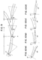
- the target course setting means 3 sets a target course OC in response to signals ND from a travelling system (See Fig. 11) informing a car for example, which way of a Y-branch the vehicle must take as follows:
- a target course OC is set on the center line of the travelling area, as shown in Fig. 10(a).
- each triangular area i indicates the area whose image can be taken by a video camera 1 of the vehicle 13.
- the travelling system When the vehicle is approaching to a Y-branch as indicated by II in Fig. 9, the travelling system having necessary travelling informations inputted therein, will send a command ND such as "Take the right way of the Y-branch appearing ahead of the car.” to the target course setting means 3 at the time when the vehicle has come to Position A a predetermined distance apart from the Y-branch.
- the target course setting means 3 sets a target course OC gradually approaching from Position A to the right way as shown in Fig. 10(b).
- the target course setting means 3 sets a target course OC extending in the right way of the Y-branch.
- the target course setting means 3 After the vehicle runs in the right way of the Y-branch, and after the vehicle enters an ordinary travelling area of relatively narrow width indicated at III in Fig. 9, the target course setting means 3 returns to the ordinary operation, setting a target course OC on the center line of the way.
- Fig. 9 corresponds to Fig. 10(a); the part (2) in Fig. 9 corresponds to Fig. 10(b); the part (3) in Fig. 9 corresponds to Fig. 10(c) and the part(4) in Fig. 9 corresponds to Fig. 10(d).
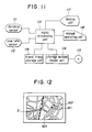
- Fig. 11 shows a travelling apparatus as comprising distance sensor 111, yaw rate sensor 112, signal processing unit 113, travel path storage unit 114, map storage medium 115, storage medium reader unit 116, display unit 117, and operating unit 118.
- a photoelectric distance measuring unit which is capable of generating a pulse signal per unit travelling distance in response to rotation of the tires of a vehicle, an electromagnetic type of distance measuring unit or a mechanical contact type of distance measuring unit may be used as a distance sensor 111.
- the yaw rate sensor 112 may comprise a gyroscope which is capable of generating a signal representing the angular velocity increment in the yaw direction while the vehicle is running.
- the signal processing unit 113 includes a CPU, ROMs for programming, RAMs for controlling etc.
- the CPU is capable of counting pulse signals from the distance sensor 111 to determine the travelling distance; determining the change of travelling direction from signals from the yaw rate sensor 112; estimating on the basis of these variables thus determined, the instantaneous position of the vehicle on the X-Y coordinates every time the vehicle has run a unit distance.
- the travel path storage unit 114 is capable of storing instantaneous car position data from the signal processing unit 113.
- the map storage medium 115 has digitalized map information stored in the form of files.
- the storage medium reader unit 116 selectively reads necessary map information from the map storage medium 115.
- the display unit 117 shows a map thus retrieved from the storage medium, and at the same time, the travel trace of the vehicle, the instantaneous position of the vehicle and the direction in which the vehicle is presumed to travel on the map.
- the operation unit 118 permits selection of map to be displayed, setting of the start position in the map appearing on the screen of the display unit, and inputting of selected commands from the travelling apparatus for guiding the vehicle along a target course on the map.
- a selected map appears on the screen of the display unit 117.
- a first mark M1 indicates the instantaneous position of the vehicle on the X-Y coordinates (the instantaneous position on the X-Y coordinates being determined from the travelling distance from the start position times the reducing scale factor of the map);
- a second mark M2 indicates the direction in which the vehicle is going; and
- a series of third marks M3 indicate the trace of the vehicle.
- points a, b and c can be put in the map to indicate particular crossings or branches, and then commands such as "Turn to the left.” or “Turn to the right” can be given when the vehicle is approaching such a point in the map.
- the signal processing unit 113 reads each travelling command to issue an appropriate command ND for example, "Take the right way of the Y-branch appearing ahead of the vehicle.” at the time when the instantaneous position mark M1 has come to be a given constant distance D apart to the point a.
- travelling apparatus It is not necessary to equip the travelling apparatus with a distance sensor 111 because the travelling distance can be determined from the speed sensor 5 of the automatic travelling apparatus shown in Fig. 1. Also, it is not necessary to equip the travelling apparatus with a yaw rate sensor 112 because the yaw rate sensor 6 of the automatic travelling apparatus shown in Fig. 1 can be commonly used.
- an automatic travelling apparatus is capable of finding out a permissible travelling area from images taken by a video camera to set a target course in the permissible travelling area; determining a steering amount appropriate for the purpose of permitting the vehicle to put itself on the target course, in consideration of the instantaneous travelling condition of the vehicle; and performing the exact steering control in terms of the steering amount.
- the exact travelling attained by the automatic travelling apparatus is attributable to two-step determination in which first, a target course is set in a permissible area, and a tentative course is set appropriate for the purpose of permitting the vehicle to put itself on the target course.
Landscapes
- Engineering & Computer Science (AREA)
- Physics & Mathematics (AREA)
- Radar, Positioning & Navigation (AREA)
- Remote Sensing (AREA)
- Automation & Control Theory (AREA)
- General Physics & Mathematics (AREA)
- Aviation & Aerospace Engineering (AREA)
- Electromagnetism (AREA)
- Multimedia (AREA)
- Computer Vision & Pattern Recognition (AREA)
- Control Of Position, Course, Altitude, Or Attitude Of Moving Bodies (AREA)
- Navigation (AREA)
- Vehicle Body Suspensions (AREA)
- Control Of Multiple Motors (AREA)
- Hydraulic Clutches, Magnetic Clutches, Fluid Clutches, And Fluid Joints (AREA)
- Steering Control In Accordance With Driving Conditions (AREA)
- Traffic Control Systems (AREA)
Claims (3)
- Automatische Fahrvorrichtung, umfassend:eine an einem Fahrzeug (13) angebrachte Bildaufnahmevorrichtung (1; 11, 12);ein Mittel (2) zum Bestimmen eines zulässigen Fahrbereichs auf der Basis eines durch die Bildaufnahmevorrichtung (1; 11, 12) aufgenommenen Bildes;ein Mittel (3) zum Setzen eines Zielkurses (OC) im somit bestimmten zulässigen Fahrbereich;ein Mittel (5, 6, 7) zum Erfassen des momentanen Fahrzustands (δ, v, γ) des Fahrzeugs (13);ein Mittel zum Bestimmen eines Lenkwerts (δ; δ'); wobei der Lenkwert (δ; δ') einem vorläufigen Kurs entspricht, der sich dem Zielkurs (OC) vor dem Fahrzeug nähert, falls das Fahrzeug (13) nicht auf dem Zielkurs (OC) fährt; undein Mittel (8, 9) zum Lenken des Fahrzeugs (13) in bezug auf den Lenkwert (δ; δ'),dadurch gekennzeichnet,
daß der momentane Fahrzustand die Fahrgeschwindigkeit (v), die Gierrate (γ) und den Reifenlenkwinkel (δ) umfaßt, und daß der Lenkwert (δ, δ') auf der Basis des momentanen Fahrzustands (δ, v, γ) bestimmt wird mit Vergleich eines angenommenen Kurses (AC) mit dem Zielkurs (OC), um zu ermöglichen, daß das Fahrzeug (13) dem Zielkurs (OC) gleichförmig folgt, wobei der angenommene Kurs (AC) durch den momentanen Fahrzustand (δ, v, γ) bestimmt ist und dem Kurs entspricht, dem das Fahrzeug folgen würde, falls keine Lenkkorrektur durchgeführt werden würde. - Automatische Fahrvorrichtung nach Anspruch 1,
bei der der Zielkurs (OC) auf der Basis der Fahrgeschwindigkeit (v) des Fahrzeugs (13) gesetzt wird, wodurch - wenn das Fahrzeugs auf einem kurvigen Weg fährt - die Krümmung des Zielkurses (OC) zunimmt, wenn die Fahrgeschwindigkeit (v) des Fahrzeugs (13) abnimmt, und umgekehrt. - Automatische Fahrvorrichtung nach einem der vorangehenden Ansprüche,
bei der ein Zielkurs (OC) nahe dem linken Rand eines relativ breiten Weges gesetzt wird, auf dem das Fahrzeug (13) fährt, wohingehen ein Zielkurs (OC) in der Mitte eines relativ schmalen Weges gesetzt wird, auf dem das Fahrzeug (13) fährt.
Applications Claiming Priority (2)
| Application Number | Priority Date | Filing Date | Title |
|---|---|---|---|
| JP199610/88 | 1988-08-10 | ||
| JP63199610A JP2660727B2 (ja) | 1988-08-10 | 1988-08-10 | 自動走行装置 |
Publications (3)
| Publication Number | Publication Date |
|---|---|
| EP0354561A2 EP0354561A2 (de) | 1990-02-14 |
| EP0354561A3 EP0354561A3 (de) | 1991-06-05 |
| EP0354561B1 true EP0354561B1 (de) | 1997-07-23 |
Family
ID=16410723
Family Applications (1)
| Application Number | Title | Priority Date | Filing Date |
|---|---|---|---|
| EP89114747A Expired - Lifetime EP0354561B1 (de) | 1988-08-10 | 1989-08-09 | Verfahren und Gerät zum automatischen Fahren |
Country Status (5)
| Country | Link |
|---|---|
| EP (1) | EP0354561B1 (de) |
| JP (1) | JP2660727B2 (de) |
| AT (1) | ATE155902T1 (de) |
| CA (1) | CA1328494C (de) |
| DE (1) | DE68928191T2 (de) |
Cited By (7)
| Publication number | Priority date | Publication date | Assignee | Title |
|---|---|---|---|---|
| US8818042B2 (en) | 2004-04-15 | 2014-08-26 | Magna Electronics Inc. | Driver assistance system for vehicle |
| US8842176B2 (en) | 1996-05-22 | 2014-09-23 | Donnelly Corporation | Automatic vehicle exterior light control |
| US8917169B2 (en) | 1993-02-26 | 2014-12-23 | Magna Electronics Inc. | Vehicular vision system |
| US8993951B2 (en) | 1996-03-25 | 2015-03-31 | Magna Electronics Inc. | Driver assistance system for a vehicle |
| US9171217B2 (en) | 2002-05-03 | 2015-10-27 | Magna Electronics Inc. | Vision system for vehicle |
| US9436880B2 (en) | 1999-08-12 | 2016-09-06 | Magna Electronics Inc. | Vehicle vision system |
| US9440535B2 (en) | 2006-08-11 | 2016-09-13 | Magna Electronics Inc. | Vision system for vehicle |
Families Citing this family (22)
| Publication number | Priority date | Publication date | Assignee | Title |
|---|---|---|---|---|
| JP2844240B2 (ja) * | 1990-03-15 | 1999-01-06 | 本田技研工業株式会社 | 自動走行装置 |
| JP2835764B2 (ja) * | 1990-03-15 | 1998-12-14 | 本田技研工業株式会社 | 自動走行装置 |
| JP2844242B2 (ja) * | 1990-03-19 | 1999-01-06 | 本田技研工業株式会社 | 自動走行装置 |
| EP0479271B1 (de) * | 1990-10-03 | 1998-09-09 | Aisin Seiki Kabushiki Kaisha | Automatisches Steuersystem für Seitenführung |
| US5307419A (en) * | 1990-11-30 | 1994-04-26 | Honda Giken Kogyo Kabushiki Kaisha | Control device of an autonomously moving body and evaluation method for data thereof |
| DE4115330C2 (de) * | 1991-05-10 | 1994-05-19 | Teldix Gmbh | Navigationsanordnung für Fahrzeuge |
| EP0514343B1 (de) * | 1991-05-16 | 1998-03-04 | Aisin Seiki Kabushiki Kaisha | Automatisches Steuersystem für Seitenführung |
| US5245422A (en) * | 1991-06-28 | 1993-09-14 | Zexel Corporation | System and method for automatically steering a vehicle within a lane in a road |
| JPH0995194A (ja) * | 1995-09-29 | 1997-04-08 | Aisin Seiki Co Ltd | 車両前方の物体検出装置 |
| DE19736965C1 (de) * | 1997-08-25 | 1999-05-06 | Mannesmann Vdo Ag | Verfahren und Anordnung zur Überprüfung der Gierrate eines sich bewegenden Objektes |
| JP3795299B2 (ja) * | 2000-04-07 | 2006-07-12 | 本田技研工業株式会社 | 車両制御装置 |
| RU2187832C2 (ru) * | 2000-10-30 | 2002-08-20 | Таганрогский государственный радиотехнический университет | Устройство управления адаптивным мобильным роботом |
| DE10255719A1 (de) * | 2002-11-29 | 2004-07-08 | Audi Ag | Fahrerassistenzvorrichtung und Fahrerassistenzverfahren |
| KR100540743B1 (ko) * | 2003-01-24 | 2006-01-10 | 최용건 | 주행편차 보정에 의한 차량의 조향각/속도조절 데이터생성장치 및 방법 |
| KR20060049706A (ko) | 2004-07-20 | 2006-05-19 | 아이신세이끼가부시끼가이샤 | 차량의 레인주행지원장치 |
| JP5568385B2 (ja) * | 2010-06-15 | 2014-08-06 | 株式会社Ihiエアロスペース | 無人移動車の走行経路計画方法 |
| JP5938336B2 (ja) * | 2012-11-22 | 2016-06-22 | 株式会社Ihiエアロスペース | 無人移動車の走行経路計画方法 |
| JP2015146748A (ja) * | 2014-02-05 | 2015-08-20 | ヤンマー株式会社 | 電動作業車両 |
| US10859389B2 (en) * | 2018-01-03 | 2020-12-08 | Wipro Limited | Method for generation of a safe navigation path for a vehicle and system thereof |
| JP2020111302A (ja) * | 2019-01-17 | 2020-07-27 | マツダ株式会社 | 車両運転支援システム及び方法 |
| JP2021109555A (ja) * | 2020-01-10 | 2021-08-02 | 株式会社リコー | 表示制御装置、システム、表示システム、情報表示方法 |
| CN116572997B (zh) * | 2023-07-11 | 2023-09-15 | 北京集度科技有限公司 | 车辆控制器、车辆及车辆控制方法 |
Family Cites Families (7)
| Publication number | Priority date | Publication date | Assignee | Title |
|---|---|---|---|---|
| US4665487A (en) * | 1984-05-25 | 1987-05-12 | Kabushiki Kaisha Meidensha | Unmanned vehicle control system and method |
| US4706771A (en) * | 1985-01-31 | 1987-11-17 | Nissan Motor Co., Ltd. | Vehicle steering control system using desired vehicle model |
| JPS626310A (ja) * | 1985-07-03 | 1987-01-13 | Hitachi Ltd | 移動体の操舵制御方法 |
| JPS6267610A (ja) * | 1985-09-20 | 1987-03-27 | Hitachi Ltd | 移動機械制御装置 |
| JPS6278613A (ja) * | 1985-10-02 | 1987-04-10 | Hitachi Ltd | 無人搬送台車の走行制御方法 |
| JPS6371104A (ja) * | 1986-09-13 | 1988-03-31 | ヤンマーディーゼル株式会社 | 無線制御式自走草刈機の制御装置 |
| US5208750A (en) * | 1987-06-17 | 1993-05-04 | Nissan Motor Co., Ltd. | Control system for unmanned automotive vehicle |
-
1988
- 1988-08-10 JP JP63199610A patent/JP2660727B2/ja not_active Expired - Lifetime
-
1989
- 1989-08-03 CA CA000607492A patent/CA1328494C/en not_active Expired - Fee Related
- 1989-08-09 EP EP89114747A patent/EP0354561B1/de not_active Expired - Lifetime
- 1989-08-09 DE DE68928191T patent/DE68928191T2/de not_active Expired - Fee Related
- 1989-08-09 AT AT89114747T patent/ATE155902T1/de not_active IP Right Cessation
Cited By (11)
| Publication number | Priority date | Publication date | Assignee | Title |
|---|---|---|---|---|
| US8917169B2 (en) | 1993-02-26 | 2014-12-23 | Magna Electronics Inc. | Vehicular vision system |
| US8993951B2 (en) | 1996-03-25 | 2015-03-31 | Magna Electronics Inc. | Driver assistance system for a vehicle |
| US8842176B2 (en) | 1996-05-22 | 2014-09-23 | Donnelly Corporation | Automatic vehicle exterior light control |
| US9436880B2 (en) | 1999-08-12 | 2016-09-06 | Magna Electronics Inc. | Vehicle vision system |
| US9171217B2 (en) | 2002-05-03 | 2015-10-27 | Magna Electronics Inc. | Vision system for vehicle |
| US9555803B2 (en) | 2002-05-03 | 2017-01-31 | Magna Electronics Inc. | Driver assistance system for vehicle |
| US8818042B2 (en) | 2004-04-15 | 2014-08-26 | Magna Electronics Inc. | Driver assistance system for vehicle |
| US9008369B2 (en) | 2004-04-15 | 2015-04-14 | Magna Electronics Inc. | Vision system for vehicle |
| US9191634B2 (en) | 2004-04-15 | 2015-11-17 | Magna Electronics Inc. | Vision system for vehicle |
| US9428192B2 (en) | 2004-04-15 | 2016-08-30 | Magna Electronics Inc. | Vision system for vehicle |
| US9440535B2 (en) | 2006-08-11 | 2016-09-13 | Magna Electronics Inc. | Vision system for vehicle |
Also Published As
| Publication number | Publication date |
|---|---|
| DE68928191D1 (de) | 1997-09-04 |
| EP0354561A3 (de) | 1991-06-05 |
| JPH0248704A (ja) | 1990-02-19 |
| DE68928191T2 (de) | 1997-11-13 |
| CA1328494C (en) | 1994-04-12 |
| JP2660727B2 (ja) | 1997-10-08 |
| ATE155902T1 (de) | 1997-08-15 |
| EP0354561A2 (de) | 1990-02-14 |
Similar Documents
| Publication | Publication Date | Title |
|---|---|---|
| EP0354561B1 (de) | Verfahren und Gerät zum automatischen Fahren | |
| US5172317A (en) | Automatic travelling apparatus | |
| US5172315A (en) | Automatic travelling apparatus and method | |
| US5233527A (en) | Automatic travelling apparatus | |
| US5367457A (en) | Apparatus and method for improving accuracy of an automatic travelling apparatus | |
| EP0446903B1 (de) | Gerät zum automatischen Fahren | |
| JP2669031B2 (ja) | 自律走行車両 | |
| CN112674646B (zh) | 基于多算法融合的自适应贴边作业方法及机器人 | |
| EP0488828B1 (de) | Steuervorrichtung für einen sich selbständig bewegenden Körper und Verfahren zur Auswertung der Daten davon | |
| US5016007A (en) | Apparatus for displaying travel path | |
| EP0810569B1 (de) | Fahrbahnsensor und Navigationssystem, das diesen Sensor verwendet | |
| JP3431962B2 (ja) | 走行区分線認識装置を備えた自動走行車両 | |
| US5170165A (en) | Apparatus for displaying travel path | |
| CN114200945B (zh) | 一种移动机器人的安全控制方法 | |
| US5003306A (en) | Apparatus for displaying current location | |
| CN115082665B (zh) | 可提高作业精度的agv小车视觉自检方法、装置及系统 | |
| EP0354562B1 (de) | Gerät zum automatischen Fahren | |
| JPH0727541A (ja) | 道路形状及び自車両位置の計測装置 | |
| JPH0789443A (ja) | 車両用自動操縦装置 | |
| JP2603523B2 (ja) | 自動走行装置 | |
| EP0448060B1 (de) | Gerät zum automatischen Fahren | |
| JP3082507B2 (ja) | 移動体の画像処理装置 | |
| CN115588299A (zh) | 一种无人驾驶车辆轨迹控制系统及方法 | |
| JP2923664B2 (ja) | 自動走行装置 | |
| Hsu et al. | Vision-based motion measurement by directly extracting image features for vehicular steering control |
Legal Events
| Date | Code | Title | Description |
|---|---|---|---|
| PUAI | Public reference made under article 153(3) epc to a published international application that has entered the european phase |
Free format text: ORIGINAL CODE: 0009012 |
|
| AK | Designated contracting states |
Kind code of ref document: A2 Designated state(s): AT CH DE FR GB IT LI SE |
|
| PUAL | Search report despatched |
Free format text: ORIGINAL CODE: 0009013 |
|
| AK | Designated contracting states |
Kind code of ref document: A3 Designated state(s): AT CH DE FR GB IT LI SE |
|
| 17P | Request for examination filed |
Effective date: 19910917 |
|
| 17Q | First examination report despatched |
Effective date: 19931222 |
|
| GRAG | Despatch of communication of intention to grant |
Free format text: ORIGINAL CODE: EPIDOS AGRA |
|
| GRAH | Despatch of communication of intention to grant a patent |
Free format text: ORIGINAL CODE: EPIDOS IGRA |
|
| GRAH | Despatch of communication of intention to grant a patent |
Free format text: ORIGINAL CODE: EPIDOS IGRA |
|
| GRAA | (expected) grant |
Free format text: ORIGINAL CODE: 0009210 |
|
| AK | Designated contracting states |
Kind code of ref document: B1 Designated state(s): AT CH DE FR GB IT LI SE |
|
| PG25 | Lapsed in a contracting state [announced via postgrant information from national office to epo] |
Ref country code: CH Free format text: LAPSE BECAUSE OF FAILURE TO SUBMIT A TRANSLATION OF THE DESCRIPTION OR TO PAY THE FEE WITHIN THE PRESCRIBED TIME-LIMIT Effective date: 19970723 Ref country code: LI Free format text: LAPSE BECAUSE OF FAILURE TO SUBMIT A TRANSLATION OF THE DESCRIPTION OR TO PAY THE FEE WITHIN THE PRESCRIBED TIME-LIMIT Effective date: 19970723 Ref country code: IT Free format text: LAPSE BECAUSE OF FAILURE TO SUBMIT A TRANSLATION OF THE DESCRIPTION OR TO PAY THE FEE WITHIN THE PRESCRIBED TIME-LIMIT;WARNING: LAPSES OF ITALIAN PATENTS WITH EFFECTIVE DATE BEFORE 2007 MAY HAVE OCCURRED AT ANY TIME BEFORE 2007. THE CORRECT EFFECTIVE DATE MAY BE DIFFERENT FROM THE ONE RECORDED. Effective date: 19970723 Ref country code: AT Effective date: 19970723 |
|
| REF | Corresponds to: |
Ref document number: 155902 Country of ref document: AT Date of ref document: 19970815 Kind code of ref document: T |
|
| REG | Reference to a national code |
Ref country code: CH Ref legal event code: EP |
|
| REF | Corresponds to: |
Ref document number: 68928191 Country of ref document: DE Date of ref document: 19970904 |
|
| PG25 | Lapsed in a contracting state [announced via postgrant information from national office to epo] |
Ref country code: SE Effective date: 19971023 |
|
| ET | Fr: translation filed | ||
| REG | Reference to a national code |
Ref country code: CH Ref legal event code: PL |
|
| PLBE | No opposition filed within time limit |
Free format text: ORIGINAL CODE: 0009261 |
|
| STAA | Information on the status of an ep patent application or granted ep patent |
Free format text: STATUS: NO OPPOSITION FILED WITHIN TIME LIMIT |
|
| 26N | No opposition filed | ||
| REG | Reference to a national code |
Ref country code: GB Ref legal event code: IF02 |
|
| PGFP | Annual fee paid to national office [announced via postgrant information from national office to epo] |
Ref country code: DE Payment date: 20070802 Year of fee payment: 19 |
|
| PGFP | Annual fee paid to national office [announced via postgrant information from national office to epo] |
Ref country code: GB Payment date: 20070809 Year of fee payment: 19 |
|
| PGFP | Annual fee paid to national office [announced via postgrant information from national office to epo] |
Ref country code: FR Payment date: 20070808 Year of fee payment: 19 |
|
| GBPC | Gb: european patent ceased through non-payment of renewal fee |
Effective date: 20080809 |
|
| REG | Reference to a national code |
Ref country code: FR Ref legal event code: ST Effective date: 20090430 |
|
| PG25 | Lapsed in a contracting state [announced via postgrant information from national office to epo] |
Ref country code: DE Free format text: LAPSE BECAUSE OF NON-PAYMENT OF DUE FEES Effective date: 20090303 Ref country code: FR Free format text: LAPSE BECAUSE OF NON-PAYMENT OF DUE FEES Effective date: 20080901 |
|
| PG25 | Lapsed in a contracting state [announced via postgrant information from national office to epo] |
Ref country code: GB Free format text: LAPSE BECAUSE OF NON-PAYMENT OF DUE FEES Effective date: 20080809 |