EP0354574B1 - Verfahren zum Verbinden von Metallbändern - Google Patents
Verfahren zum Verbinden von Metallbändern Download PDFInfo
- Publication number
- EP0354574B1 EP0354574B1 EP89114834A EP89114834A EP0354574B1 EP 0354574 B1 EP0354574 B1 EP 0354574B1 EP 89114834 A EP89114834 A EP 89114834A EP 89114834 A EP89114834 A EP 89114834A EP 0354574 B1 EP0354574 B1 EP 0354574B1
- Authority
- EP
- European Patent Office
- Prior art keywords
- spliced
- roller
- rolled
- metal
- metal web
- Prior art date
- Legal status (The legal status is an assumption and is not a legal conclusion. Google has not performed a legal analysis and makes no representation as to the accuracy of the status listed.)
- Expired - Lifetime
Links
- 229910052751 metal Inorganic materials 0.000 title claims description 128
- 239000002184 metal Substances 0.000 title claims description 128
- 238000000034 method Methods 0.000 title claims description 29
- 238000005096 rolling process Methods 0.000 claims description 41
- 230000009467 reduction Effects 0.000 claims description 40
- 238000003466 welding Methods 0.000 claims description 10
- 238000000576 coating method Methods 0.000 description 38
- 239000011248 coating agent Substances 0.000 description 37
- 238000012360 testing method Methods 0.000 description 29
- 230000037303 wrinkles Effects 0.000 description 15
- 229910052782 aluminium Inorganic materials 0.000 description 11
- XAGFODPZIPBFFR-UHFFFAOYSA-N aluminium Chemical compound [Al] XAGFODPZIPBFFR-UHFFFAOYSA-N 0.000 description 11
- 230000000694 effects Effects 0.000 description 6
- 238000005336 cracking Methods 0.000 description 5
- 238000007788 roughening Methods 0.000 description 5
- 238000005520 cutting process Methods 0.000 description 4
- 238000004519 manufacturing process Methods 0.000 description 4
- 238000004381 surface treatment Methods 0.000 description 4
- 238000007639 printing Methods 0.000 description 3
- MCMNRKCIXSYSNV-UHFFFAOYSA-N Zirconium dioxide Chemical compound O=[Zr]=O MCMNRKCIXSYSNV-UHFFFAOYSA-N 0.000 description 2
- 238000005452 bending Methods 0.000 description 2
- 230000008859 change Effects 0.000 description 2
- 238000010276 construction Methods 0.000 description 2
- 238000011156 evaluation Methods 0.000 description 2
- 230000003252 repetitive effect Effects 0.000 description 2
- 229910000997 High-speed steel Inorganic materials 0.000 description 1
- 241000167880 Hirundinidae Species 0.000 description 1
- -1 Si3N4 Chemical class 0.000 description 1
- 229910052581 Si3N4 Inorganic materials 0.000 description 1
- 229910000831 Steel Inorganic materials 0.000 description 1
- ATJFFYVFTNAWJD-UHFFFAOYSA-N Tin Chemical compound [Sn] ATJFFYVFTNAWJD-UHFFFAOYSA-N 0.000 description 1
- PNEYBMLMFCGWSK-UHFFFAOYSA-N aluminium oxide Inorganic materials [O-2].[O-2].[O-2].[Al+3].[Al+3] PNEYBMLMFCGWSK-UHFFFAOYSA-N 0.000 description 1
- 239000011324 bead Substances 0.000 description 1
- 238000005422 blasting Methods 0.000 description 1
- 239000000919 ceramic Substances 0.000 description 1
- 238000007796 conventional method Methods 0.000 description 1
- 229910052593 corundum Inorganic materials 0.000 description 1
- 230000003247 decreasing effect Effects 0.000 description 1
- 238000001035 drying Methods 0.000 description 1
- 230000006872 improvement Effects 0.000 description 1
- 238000003754 machining Methods 0.000 description 1
- 235000012054 meals Nutrition 0.000 description 1
- 150000001247 metal acetylides Chemical class 0.000 description 1
- 238000012986 modification Methods 0.000 description 1
- 230000004048 modification Effects 0.000 description 1
- 229910003465 moissanite Inorganic materials 0.000 description 1
- 230000002093 peripheral effect Effects 0.000 description 1
- 238000003825 pressing Methods 0.000 description 1
- 230000002265 prevention Effects 0.000 description 1
- 229910010271 silicon carbide Inorganic materials 0.000 description 1
- 238000005507 spraying Methods 0.000 description 1
- 239000010959 steel Substances 0.000 description 1
- 239000000126 substance Substances 0.000 description 1
- 238000012546 transfer Methods 0.000 description 1
- 229910001845 yogo sapphire Inorganic materials 0.000 description 1
Images


Classifications
-
- B—PERFORMING OPERATIONS; TRANSPORTING
- B21—MECHANICAL METAL-WORKING WITHOUT ESSENTIALLY REMOVING MATERIAL; PUNCHING METAL
- B21B—ROLLING OF METAL
- B21B15/00—Arrangements for performing additional metal-working operations specially combined with or arranged in, or specially adapted for use in connection with, metal-rolling mills
- B21B15/0085—Joining ends of material to continuous strip, bar or sheet
Definitions
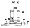
- FIG. 13 there is shown a conventional splicing apparatus in which a roller 50 with projected portion 54 is used to reduce the thickness of a metal web 52 in part. That is, the roller 50 has a projected portion 54 existing successively in the outer periphery thereof and the metal web is held or fixed by a fixing jig 56 to a table 58 and is then rolled by the projected portion 54.
- FIG 14 there is shown a conventional splicing method in which the projected portion 54 of the projection roller 50 are used to reduce a level difference in a spliced portion 60 between the two metal webs 52,52 to improve the shape of the spliced portion so as to prevent centralization of stresses.
- the spliced portion 60 is situated on a back bar 62, is held or fixed by the fixing jigs shown in Fig. 14 or by a suction table 64, and is rolled by the projected portion 54 of the above-mentioned roller 50.
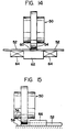
- Fig. 15 there is shown a method of rolling the end portion (the portion to be spliced) of the metal web 52 by use of the projected portion 54 of the roller 50 and, according to this method, the strip-shaped metal plate 52 is held or fixed by a stop jig 66 at the portion thereof adjacent to the passage of the roller 50 so as to prevent the metal web 52 from escaping out of position.
- a coating step of photo-sensitive layer in manufacturing a lithographic (planographic) printing plate when the constrictions and/or wrinkles in the spliced portions are passed, through a coating device, the coating device must shunted or moved aside in order to prevent against damage. Also, when the coating device is not shunted, the constrictions and/or wrinkles may swallow air bubbles therein, which has an ill effect on the state of the coated layer, resulting in a poor quality.
- the end portion (the portion to be spliced) of a metal web is to be previously rolled, if the width of the projected portion of the roller with projected portion is small with respect to a distance between the stop jig and the metal web end portion, then the metal web is very easy to escape out of place. Further, if the rolling pressure or downward pressure is decreased for prevention of escape of the metal web, then a working efficiency in rolling is disadvantageously lowered.
- the surface of the spliced portion may be hard to be roughened.
- the metal structure of the spliced portion has been charged or deformed, when the metal web is surface roughened in an electro-chemical manner, the spliced portion cannot be surface roughened sufficiently.
- the insufficiently surface roughened spliced portion provides a surface which is poor in wettability, when it passes through a coating step of such as a photosensitive layer or the like which is one of the following steps, the spliced portion may be in part short of the amount of application of coating solution and, the coating may be applied to such insufficient portion too much, which occurs just after the short application of the coating solution.
- the projected portion of the rolling roller is transferred to the spliced portion, there is produced a level difference between the rolled portion and the unrolled portion.
- This level difference gives rise to various disadvantages in a surface treatment step which is one of the following steps. For example, in a coating step of a photosensitive layer in a planographic printing plate manufacturing process, when the level different section of the spliced portion is passed through it swallows in air bubbles, which has an ill effect on the coated state of the metal web spliced portion, resulting in the deteriorated quality of the metal web. As the difference between the thickness of the metal web to be spliced is increased, the above-mentioned level difference in the spliced portion is increased.
- the present invention aims at eliminating the drawbacks found in the above-mentioned prior art method.
- a rolling operation is carried out by use of a roller including a projected portion which is formed to projected slightly out of a hold portion of the roller, that is, with the metal web being held by the hold portion of the reduction roller, the spliced portion or the portion to be spliced of the metal web is rolled by the roller. Due to this, the spliced portion or the portion to be spliced of the shaped metal web to be rolled can be rolled with no constrictions, wrinkles or escape occurring, so that the spliced portion or the portion to be spliced can be strengthened, a working efficiency can be maintained reasonably, and no disadvantages can be provided in a surface treatment step.
- a roughened surface portion is formed in the surface of a reduction roller.
- the surface of the welded spliced portion can be roughened by transferring the roughened surface portion and, therefore, in a coating step, the wettability of the spliced portion surface can be well maintained to thereby prevent occurrence of poor coating.
- a metal web splicing method in which metal webs are butted against each other or slightly lapped on each other and then spliced together by welding and in which a roller comprising a hold portion having a first radius and a projected portion having a second radius greater than the first radius is used to roll the welded spliced portion in such a manner that, while the metal web is being held by the hold portion of the roller, the welded spliced portion is rolled by the projected portion of the roller, wherein a level difference portion between the projected and hold portions is formed in a tapered or curved shape.
- the level difference portion existing between the projected and hold portions of the roller is shaped, tapered or curved to thereby smooth the level difference in the metal web spliced portion to be rolled and, therefore, there is eliminated any influences due to swallow-in of air bubbles or the like to thereby prevent occurrence of poor quality spliced metal plates.
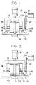
- the splicing apparatus mainly consists of a splicing table 10, a reduction roller 12, a back bar 14, a shaft 16, a motor 18, a downward pressing cylinder 20 and the like.
- the roller 12 comprises a hold portion 12A having a first radius and a projected portion 12B having a second radius.
- a difference between the first and second radius, that is, an amount of projection of the projected portion 12B may be 0.1 ⁇ 5.0 times, preferably, 0.5 ⁇ 2.0 times the thickness of a member to be rolled.
- the reduction roller 12 can be formed of one of a high speed steel such as SKH 9 or the like, a dies steel such as SKD 11 or the like, cemented carbides, ceramics such as Si 3 N 4 , SiC, Al 2 O 3 , ZrO 2 or the like, and CBN. Also, if necessary, the surface of the reduction roller 12 may be coated with TiN, WC or the like in order to improve its wear resistance and to prevent the member to be rolled from being condensed and attached to the roller.
- the splicing table 10 is set on a holder (which is not shown) of the splicing apparatus and the back bar 14 is fixed to the substantially central portion of the table 10.
- the reduction roller 12 is arranged such that it can be moved on the splicing table 10 along the spliced portion and it is also rotatably journaled by the shaft 16. Further, the reduction roller 12 can be pushed toward the splicing table 10 by means of operation of the cylinder 20.
- the roller 12 can be rotated and driven by the motor 18 through a gear 24A, a chain 22 and a gear 24B.
- a metal web 26 to be spliced is held or fixed by a stop jig 28 to the splicing table 10 in such a manner that the central part of the portion thereof to be rolled is situated on the back bar 14.
- the reduction roller 12 is pushed down by the cylinder 20 so that the web metal plate 26 is pressed and fixed by the hold portions 12A, 12A.
- the motor 18 is driven, then the rotational movements of the motor 18 are transmitted to the reduction roller 12 through the gear 24A, chain 22 and gear 24, whereby the metal web can be rolled while the central part of the above-mentioned rolling portion thereof is held between the projected portion 12B and the back bar 14.
- This rolling operation can reduce in part the thickness of the meal web 26.
- the present splicing apparatus is able to restrict the distortion that would inevitably occur, when compared with a conventional splicing apparatus using a conventional roller with projected portion. That is, when the metal web 26 is thin and has a low rigidity, the constrictions and/or wrinkles that would occur in the central part of the rolling portion can be reduced. For this reason, there is eliminated the need to limit the magnitude of the push-down forces and thus a working efficiency will never be lowered.
- the metal web 26 is held or fixed onto the splicing table 10 by the stop jig 28.
- the roller 12 is pushed down by the cylinder 20 and the central part of the rolling portion is held between the fixed by the projected portion of the roller 12 and the back bar 14.
- the projected portion 12B rolls the end portion of the butted or lapped portion to be spliced of the metal web.
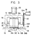
- Fig. 3 there is shown a method of rolling the spliced portion of metal webs having different thicknesses, illustrating a case in which, out of two recrystallized portions 32A, 32B occurring in the weldedly spliced portion, the recrystallized portion 32A, and a metal web 26A and a fused portion 32C respectively adjoining the recrystallized portion 32A are rolled by use of the splicing apparatus already discussed in connection with Fig. 1.
- the metal web 26 that is spliced by welding is fixed onto the splicing table 10 by the stop jig 28.
- the reduction roller 12 is pushed down by the cylinder 20 and the central part of the rolling portion is held between and fixed by the back bar 14 and the projected portion of the reduction roller 12.
- the portion of the metal web 26 adjacent to the central part of the rolling portion is held against the table 10 and back bar 14 by the hold portions 12A of the reduction roller and the recrystallized portion 32A, fused portion 32C and metal web 26A can be rolled simultaneously by the projected portion 12B. That is, the recrystallized portion 32A as well as the fused portion 32C and metal web 26A respectively adjoining the recrystallized portion 32A can be rolled in such a manner that they have substantially the same thickness (more exactly, the difference among their respective thicknesses is within 30%).
- recrystallized portion 32B, fused portion 32C and metal web 26B can be rolled similarly to the above-mentioned ones.
- a predetermined range of the spliced portion can be rolled and, therefore, even if a narrow range is selectively rolled with a high pressure, the constrictions and/or wrinkles are hard to occur. For this reason, only the thick part of the butt or lap spliced portion can be rolled to thereby make all of uniform thickness, so that the centralization of stresses on the spliced portion can be reduced to thereby improve the flatness of the neighbouring portion of the spliced portion.
- the centralization of stresses on the recrystallized portion can be reduced.
- the splicing strength can be improved.
- two aluminum webs one of them having a thickness of 0.30mm and a width of 200mm and the other having a thickness of 0.15mm and a width of 200mm, are lapped by 1mm on each other and the lapped portion is TIG arc welded at the speed of 1m/min. so that the two aluminum webs are spliced together.
- the spliced portion is rolled by a reduction roller having a width of 4mm and an amount of projection of 0.3mm in such a manner that a difference between the thicknesses of the neighboring portions of the recrystallized portion occurring on the side of the aluminum webs having a width of 0.15mm can be reduced. This is called a sample No. 1.
- the above-mentioned spliced portion of the two aluminum webs is rolled similarly by use of a roller with projected portion having a width 4mm and amount of projection of 6mm. This is called a sample No. 2. Further, after two aluminum webs are spliced by welding, the thickest part of the spliced portion is rolled by a flat roller having no projected portion. This is called a sample No. 3.
- the end portion to be spliced of the aluminum plate having a thickness of 0.30mm is rolled down to a thickness of 0.20mm by use of a reduction roller having a width of 4m and an amount of projection of 0.30mm before it is spliced by welding, and, after then, the spliced portion is further rolled similarly as in the sample No. 3.
- a sample No. 4 a sample, which has been rolled by use of a roller with projected portion having a width of 4mm and an amount of projection of 6mm before it is spliced, is called a sample No. 5.
- test samples No. 1 to No.5 have been put to a pass roller pass test, with a tension of 75kg being loaded onto them. That is, they are respectively passed round a circulating path consisting of 2 rubber rollers ( ⁇ 600), 22 rubber rollers ( ⁇ 200) and 2 rubber rollers ( ⁇ 180) and the numbers of rounds or laps before they are cut off are examined, respectively.
- the test results are shown in Table 1. TABLE 1 SAMPLE No.
- the sample No.1 and No.4 are samples which have been rolled by use of reduction roller according to the invention, while the samples No.2, No.3 and No.5 are samples which have been rolled by use of a conventional reduction roller.
- the spliced portion is rolled while pushing and holding other portions than the portion to be rolled, so that the constructions and/or wrinkles can be reduced and thus a high quality and local rolling operation can be realized. If this is combined with a butt splicing operation, then the splicing strength can be enhanced to a great extent.
- FIG. 4 there is shown an explanatory view of another embodiment of a metal web splicing apparatus according to the invention.
- the same or similar parts as in the embodiment shown in Figs. 1 to 3 are given the same designations and the description thereof is omitted here.
- Fig.5 there is shown an enlarged view of the outer peripheral portion of a reduction roller.
- the above-mentioned reduction roller 12 is able to transfer the roughened surface to the surface of the spliced portion.
- the metal web 26 is held and fixed by a stop jig 28 to the splicing table 10 such that the central part of the rolling portion is placed on the upper surface of the back bar 14.
- the reduction roller 12 is pushed downward by the cylinder 20, causing the hold portions 12A and 12A to press and fix the metal web 26.
- the motor 18 is driven, then the rotational motion of the motor 18 is transmitted through the gear 24A, chain 22 and gear 24B to the reduction roller 12 and the spliced portion is rolled with the central part of the rolling portion held between the projected portion 12B and the back bar 14.
- the central part of the rolling portion is rolled by the projected portion 12B while it is held by the hold portion 12A to thereby be able to reduce in part the thickness of the metal web 26. Due to the fact that the shape of the roughened surface portion 13 of the surface of the reduction roller 12 is transferred to the spliced portion, after rolled, the shortage of surface roughening in the spliced portion in a step of roughening the surface of the metal web can be compensated. Owing to this, the wettability in a coating step can be satisfied.
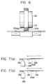
- FIG. 6 there is shown another embodiment of a splicing method according to the invention, in which, while a knurled roller 112 with projected portion is used to reduce the thickness of the raised section 132A of a spliced portion 132, a surface roughened portion 113 formed in the surface of the roller 112 is transferred to the spliced portion 132. Due to this, similarly as in the above-mentioned embodiment, the wettability of the spliced portion can be satisfied in a step of coating metal webs.
- Figs. 7(a) and (b) are respectively side views of a coating device applied to the above-mentioned coated state comparison test.
- two metal webs 126 and 134 which are different in thickness from each other and are spliced together by welding, are delivered in a direction of an arrow shown in this figure, with the spliced portion thereof facing downwardly, and coating solution are then applied to the lower surfaces of the metal webs 126 and 134 by use of a coating device 136 disposed below the two metal webs.
- Fig. 7(b) two metal webs 134, 134 having the same thickness are coated in a coating method similar to that in Fig. 7(a).
- test samples No.11, No.12 for Table 2 two aluminum plates, one having a thickness of 0.30mm and a width of 200mm and the other having a thickness of 0.15mm and a width of 200mm, are lapped by 1mm on each other and then TIG arc welded at the speed of 6m/min. for splicing.
- Test samples No.13 and 14 are produced by lapping two aluminum webs each having a thickness of 0.30mm and a width of 200mm by 1mm on each other and splicing them by welding similarly to the above-mentioned test samples.
- test samples No.11 and 13 are rolled by a reduction roller which is provided in the outer periphery thereof with a rough surface having a pitch of 0.20mm and a depth of 0.30mm.
- the test samples No.12 and No.14 are rolled by a conventional roller having a polished surface.
- test samples No.11 to No.14 are surface roughened in the same manner.
- the samples No.11 and No.12 are put to a test in which a photo-sensitive layer is coated in a method shown in Fig. 7(a)
- the samples No.13 and No.14 are put to a test in which a photo-sensitive layer is coated in a method shown in Fig. 7(b).
- Table 2 there are shown the results of the layer coating test in such a manner that x is used to represent a case when a thick coating occurs and O a case when no tick coating occurs.
- Figs. 8(a) to (d) there are shown typical views which respectively illustrate the characteristics of the coated states of the above-mentioned test samples No.1 to No.4.
- numeral 136 designates a coating device and 138 a coated solution.
- a splicing apparatus of the invention by forming a roughened surface portion in the surface of a reduction roller, the spliced portion can be roughened sufficiently when rolling and also the wettability of the spliced portion in a coating step can be kept well, so that the coating aptitude of the spliced portion can be improved. This means that the quality of the spliced metal webs can be improved well.
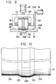
- FIG. 9 there is shown an explanatory view of another embodiment of a metal web splicing apparatus according to the invention.
- the same or similar parts thereof as in the above-mentioned embodiment shown in Figs. 1 to 3 are given the same designations and the description thereof is omitted here.
- a reduction roller 12 comprises hold portions 12A each having a first radius and a projected portion 12B having a second radius. Also, in a level difference portions between the projected portion 12B and the hold portions 12A, as shown in Fig. 10, there are formed tapered or curved surfaces 12C and 12C. Further, a difference between the first and second radius, that is, an amount of projection of the projected portion 12B may be 0.1 ⁇ 5.0 or preferably 0.5 ⁇ 2.0 times the thickness of the member to be rolled. And, the length of the tapered portion may be 0.15mm ⁇ 2.0mm or preferably 0.5mm ⁇ 1.5mm.
- the metal web 26 is held and fixed by the stop jig 28 to the splicing table 10 in such a manner that the central part of the portion to be rolled is placed on the back bar 14.
- the reduction roller 12 is pushed downward by the cylinder 20 so that the metal web 26 is pressed and fixed by the hold portions 12A, 12A.
- the motor 18 is driven, then the rotational motion of the motor 18 is transmitted through the gear 24A, chain 22 and gear 24B to the reduction roller 12 and the metal web 26 is rolled with the central part of the rolling portion being held between the projected portion 12B and the back bar 14, so that the thickness of the metal web 26 can be reduced in part.
- the central part of the rolling portion is rolled by the projected portion 12B while it is held by the hold portions 12A. Since the shape of the tapered or curved surface is transferred to the edge of the spliced portion after it is rolled, the spliced portion can be rolled smoothly.
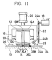
- Fig. 11 there is shown a state in which two metal webs 26 and 34 different in thickness from each other are spliced by welding, and, among two recrystallized portions 32A, 32B, one recrystallized portion 32A and a metal web 26A and a fused portion 32C respectively adjoining the recrystallized portion 32A are rolled by use of the splicing apparatus which has been described in connection with Fig. 9.
- the weldedly spliced metal web 26 is fixed onto the splicing table 10 by the stop jig 28, Next, the roller 12 is pushed downward by the cylinder 20 and the central part of the rolling portion is held between and fixed by the projected portion of the roller and the back bar 14. After then, the portion of the metal web 26 adjacent to the central part of the rolling portion is pressed against the splicing table 10 and back bar 14 by the hold portion 12, and the recrystallized portion 32A, fused portion 32C and the leading end portion 26A of the metal web 26 are rolled simultaneously by the projected portion 12B.
- the thicknesses of not only the recrystallized portion 32A but also the fused portion 32C and the metal web leading end portion 26A can be made to be substantially equal to one another (more exactly, the difference among the thicknesses of these three portions is within 30%).
- the tapered or curved surface 12C allows the spliced portion to be rolled in such a manner that the thickness of the fused portion 32C can be tapered.
- the metal web splicing apparatus of the invention due to the fact that the thickness varying section of the spliced portion is formed smooth, that is, tapered or curved, it is possible to provide a spliced portion which is hard to break and at the same time the quality of the spliced metal web can be maintained when the coating solutions are applied.
- the differences among the thicknesses of the fused portion are formed tapered to thereby reduce the web thickness difference in the neighboring portions of the recrystallized portion having a low repetitive bending strength, the centralization of stresses on the recrystallized portion can be reduced and at the same time it is possible to prevent the lowering of the quality of the spliced metal web when it is coated with coating solutions.
- the weldedly spliced portion is rolled by different rollers, that is, a roller having a projected portion including a tapered portion of 0.15mm in width, a roller having a projected portion including a tapered portion of 1.0mm in width, a roller having a projected portion including a tapered portion of 2.0mm in width, and a roller having a projected portion including no tapered portion, respectively.
- four kinds of coating tests were conducted. The four tests, that is, Tests A, B, C and D are typically illustrated in Figs. 12(a) to (d), respectively.
- numeral 36 designates a coating device and 38 a coated layer.
- Evaluation items in Table 3 includes whether swallow-in of air bubbles is present or not, the length of a coating line or stripe occurring when the air bubbles are swallowed in, whether a thick coating is present or not in the neighboring portion of the spliced portion when the air bubbles are swallowed in, and the length of range of the thick coating occurred.
- the level different portion existing between the projected portion of the roller and the hold portion thereof is shaped in a tapered or curved surface to thereby prevent the shape of the level different portion being transferred to the spliced portion, there is eliminated the influences due to the swallowing-in of the air bubbles or the like so that the coated state can be improved, resulting in the enhancement of the quality of the spliced metal web.
Landscapes
- Engineering & Computer Science (AREA)
- Mechanical Engineering (AREA)
- Replacement Of Web Rolls (AREA)
- Metal Rolling (AREA)
- Winding, Rewinding, Material Storage Devices (AREA)
Claims (3)
- Verfahren zum Verbinden des vorderen Endes (26, 34, 126, 134) eines folgenden Metallbandes mit einem hinteren Ende (26, 34, 126, 134) eines vorhergehenden Metallbandes, bei dem die Metallbänder (26, 34, 126, 134) stumpfgestoßen oder leicht überlappt und durch Schweißen überlappend verbunden werden, und mit einer Reduzierwalze (12), die einen Halteabschnitt (12A) mit einem ersten Radius und einen vorstehenden Abschnitt (12B) mit einem zweiten Radius, der etwas größer ist als der erste Radius, umfaßt, der verbundene Abschnitt (32C) der Metallbänder (26, 34, 126, 134) durch den vorstehenden Abschnitt (12B) der Walze (12) gewalzt wird, wobei beide Seiten des verbundenen Abschnitts (32C) der Metallbänder (26, 34, 126, 134) durch den Halteabschnitt (12A) der Walze (12) gehalten und fixiert werden, wobei vor dem Reduzierwalzen die zu verbindenden Metallbänder jeweils mit einer Klemmeinrichtung (28) an einen Verbindungstisch (10) geklemmt werden.
- Verfahren nach Anspruch 1, wobei die Metallbänder (26, 34, 126, 134) stumpfgestoßen oder leicht überlappt werden und durch Schweißen überlappend verbunden werden, und wobei ein verbundener Abschnitt (32C) des Metallbandes mit dem vorstehenden Abschnitt (12B) der Walze (12) gewalzt wird, wobei beide Seiten des verbundenen Abschnitts (32C) des Metallbandes durch den Halteabschnitt (12A) der Walze gehalten und fixiert werden.
- Verfahren nach Anspruch 1, wobei, während das Metallband durch den Halteabschnitt der Reduzierwalze gehalten und fixiert wird, wenigstens einer von zwei rekristallisierten Abschnitten, die in dem schweißend verbundenen Abschnitt auftreten, und die beiden benachbarten Abschnitte der rekristallisierten Abschnitte durch den vorstehenden Abschnitt der Walze so gewalzt werden, daß Dickenunterschiede zwischen den jeweiligen Abschnitten im Bereich bis zu 30% liegen.
Applications Claiming Priority (6)
| Application Number | Priority Date | Filing Date | Title |
|---|---|---|---|
| JP63201336A JPH0698510B2 (ja) | 1988-08-11 | 1988-08-11 | 帯状金属板の接合方法及び接合装置 |
| JP201336/88 | 1988-08-11 | ||
| JP1142722A JP2560112B2 (ja) | 1989-06-05 | 1989-06-05 | 帯状金属板の接合装置 |
| JP142721/89 | 1989-06-05 | ||
| JP142722/89 | 1989-06-05 | ||
| JP1142721A JP2560111B2 (ja) | 1989-06-05 | 1989-06-05 | 帯状金属板の接合方法及び接合装置 |
Publications (3)
| Publication Number | Publication Date |
|---|---|
| EP0354574A2 EP0354574A2 (de) | 1990-02-14 |
| EP0354574A3 EP0354574A3 (de) | 1992-05-06 |
| EP0354574B1 true EP0354574B1 (de) | 1997-03-12 |
Family
ID=27318496
Family Applications (1)
| Application Number | Title | Priority Date | Filing Date |
|---|---|---|---|
| EP89114834A Expired - Lifetime EP0354574B1 (de) | 1988-08-11 | 1989-08-10 | Verfahren zum Verbinden von Metallbändern |
Country Status (3)
| Country | Link |
|---|---|
| US (1) | US5074457A (de) |
| EP (1) | EP0354574B1 (de) |
| DE (1) | DE68927840T2 (de) |
Cited By (1)
| Publication number | Priority date | Publication date | Assignee | Title |
|---|---|---|---|---|
| RU2216416C2 (ru) * | 1996-11-28 | 2003-11-20 | СМС Шлеманн-Зимаг АГ | Установка и способ горячей прокатки плоского проката |
Families Citing this family (9)
| Publication number | Priority date | Publication date | Assignee | Title |
|---|---|---|---|---|
| US5217155A (en) * | 1991-08-16 | 1993-06-08 | Kawasaki Steel Corporation | Method of continuously hot-rolling sheet bars |
| JP2817075B2 (ja) * | 1992-02-21 | 1998-10-27 | 富士写真フイルム株式会社 | 表面に感光液を塗布する帯状金属板の接合方法 |
| US5957369A (en) * | 1996-05-09 | 1999-09-28 | Elpatronic Ag | Method for connecting two workpieces together |
| CA2347427A1 (en) * | 1998-11-18 | 2000-05-25 | Elpatronic Ag | Method and device for laser welding metal sheets |
| US6886251B1 (en) | 2001-01-31 | 2005-05-03 | Vp Buildings, Inc. | Beam fabrication system |
| WO2007134459A1 (en) * | 2006-05-23 | 2007-11-29 | Innovequity Inc. | Joist forming construction machine and methods |
| CN102500868B (zh) * | 2011-11-01 | 2014-07-09 | 上海锅炉厂有限公司 | 一种在卧式预热器中心筒的筒体上焊接耳板的加工方法 |
| CN111215793A (zh) * | 2018-11-26 | 2020-06-02 | 晟通科技集团有限公司 | 滚焊总成 |
| CN111215843B (zh) * | 2019-10-16 | 2021-08-06 | 南京航空航天大学 | 一种电弧送丝增材斜辊组合轮热碾压制造方法及装置 |
Family Cites Families (11)
| Publication number | Priority date | Publication date | Assignee | Title |
|---|---|---|---|---|
| US2376604A (en) * | 1943-03-24 | 1945-05-22 | Frank C Lathrop | Prefabricating jig |
| US3119289A (en) * | 1960-07-01 | 1964-01-28 | Nat Electric Welding Machines | Method for planishing a pair of seam-joined metal sheets |
| US3421676A (en) * | 1966-08-02 | 1969-01-14 | Reynolds Metals Co | Apparatus for joining metal products |
| US3737979A (en) * | 1971-08-05 | 1973-06-12 | Anaconda American Brass Co | Method of manufacturing longitudinally welded strips of different thicknesses and widths |
| BE800507A (fr) * | 1973-06-06 | 1973-10-01 | Gabriels Sprl Ets J B | Procede de conditionnement de la zone de soudure d'un corps cylindrique d'un emballage metallique et emballage resultant |
| SU789258A1 (ru) * | 1979-06-28 | 1980-12-26 | Предприятие П/Я В-2775 | Способ изготовлени сварных соединений |
| JPS5870978A (ja) * | 1981-10-22 | 1983-04-27 | Mitsubishi Electric Corp | 鋼板の突合せ溶接方法 |
| JPS597446A (ja) * | 1982-07-02 | 1984-01-14 | Nippon Denso Co Ltd | 偏平チューブとコルゲートフィンの組付方法 |
| JPS59212103A (ja) * | 1983-05-18 | 1984-12-01 | Mitsubishi Electric Corp | 圧延異形板の製造方法 |
| JPH0522393Y2 (de) * | 1986-04-30 | 1993-06-08 | ||
| DE3824698C2 (de) * | 1987-07-20 | 1999-05-12 | Fuji Photo Film Co Ltd | Verfahren und Einrichtung zum Stoßverbinden von Metallbahnen oder -bändern |
-
1989
- 1989-08-10 DE DE68927840T patent/DE68927840T2/de not_active Expired - Fee Related
- 1989-08-10 EP EP89114834A patent/EP0354574B1/de not_active Expired - Lifetime
-
1991
- 1991-01-31 US US07/649,257 patent/US5074457A/en not_active Expired - Lifetime
Cited By (1)
| Publication number | Priority date | Publication date | Assignee | Title |
|---|---|---|---|---|
| RU2216416C2 (ru) * | 1996-11-28 | 2003-11-20 | СМС Шлеманн-Зимаг АГ | Установка и способ горячей прокатки плоского проката |
Also Published As
| Publication number | Publication date |
|---|---|
| EP0354574A3 (de) | 1992-05-06 |
| EP0354574A2 (de) | 1990-02-14 |
| DE68927840D1 (de) | 1997-04-17 |
| US5074457A (en) | 1991-12-24 |
| DE68927840T2 (de) | 1997-06-19 |
Similar Documents
| Publication | Publication Date | Title |
|---|---|---|
| EP0354574B1 (de) | Verfahren zum Verbinden von Metallbändern | |
| EP0038646A1 (de) | Verfahren zur Herstellung geschweisster Dosenkörper | |
| JP2009008073A (ja) | 排ガス浄化装置の加工方法 | |
| CA2187720A1 (en) | Method and an apparatus for manufacturing wire | |
| JP3826455B2 (ja) | グラビア塗布装置及びその製造方法 | |
| JP3637815B2 (ja) | シーム溶接用銅ワイヤへの金属錫コーティング装置およびシーム溶接機 | |
| JP2560111B2 (ja) | 帯状金属板の接合方法及び接合装置 | |
| JP2560117B2 (ja) | 帯状金属板の接合装置 | |
| JPS63199024A (ja) | ロ−ラレベラ | |
| JPH072155Y2 (ja) | 帯状金属板の接合装置 | |
| JP3704208B2 (ja) | 走間溶接設備の加熱型クランプ装置およびこのクランプ装置を用いたクランプ方法 | |
| JP2560112B2 (ja) | 帯状金属板の接合装置 | |
| JP3317269B2 (ja) | グラビア印刷ロール及びその製造方法 | |
| JP2738117B2 (ja) | 多段圧延機 | |
| JPH01178319A (ja) | ローラレベラ | |
| JPH08174015A (ja) | ステンレス鋼用冷間圧延機の補助ロールおよびその表面加工方法 | |
| JPS63199023A (ja) | ロ−ラレベラ | |
| JPH0698510B2 (ja) | 帯状金属板の接合方法及び接合装置 | |
| JPH09176820A (ja) | 冷間鋼帯搬送用プロセスロール | |
| JPH0255672A (ja) | 帯状金属板の接合装置 | |
| JPH0669566B2 (ja) | 鋼板の調質圧延方法 | |
| JPH0753821Y2 (ja) | シーム溶接装置 | |
| JPH11277103A (ja) | 金属材の圧延方法および圧延設備 | |
| JPH09157826A (ja) | 冷間鋼帯の搬送用プロセスロール | |
| JP3241507B2 (ja) | 板圧延機 |
Legal Events
| Date | Code | Title | Description |
|---|---|---|---|
| PUAI | Public reference made under article 153(3) epc to a published international application that has entered the european phase |
Free format text: ORIGINAL CODE: 0009012 |
|
| AK | Designated contracting states |
Kind code of ref document: A2 Designated state(s): DE NL |
|
| RIN1 | Information on inventor provided before grant (corrected) |
Inventor name: KAKEI, TSUTOMU Inventor name: SAWADA, HIROKAZU Inventor name: MATSUKI, MASAYA |
|
| PUAL | Search report despatched |
Free format text: ORIGINAL CODE: 0009013 |
|
| AK | Designated contracting states |
Kind code of ref document: A3 Designated state(s): DE NL |
|
| 17P | Request for examination filed |
Effective date: 19921104 |
|
| 17Q | First examination report despatched |
Effective date: 19940802 |
|
| GRAG | Despatch of communication of intention to grant |
Free format text: ORIGINAL CODE: EPIDOS AGRA |
|
| GRAH | Despatch of communication of intention to grant a patent |
Free format text: ORIGINAL CODE: EPIDOS IGRA |
|
| GRAH | Despatch of communication of intention to grant a patent |
Free format text: ORIGINAL CODE: EPIDOS IGRA |
|
| GRAA | (expected) grant |
Free format text: ORIGINAL CODE: 0009210 |
|
| AK | Designated contracting states |
Kind code of ref document: B1 Designated state(s): DE NL |
|
| PG25 | Lapsed in a contracting state [announced via postgrant information from national office to epo] |
Ref country code: NL Free format text: LAPSE BECAUSE OF FAILURE TO SUBMIT A TRANSLATION OF THE DESCRIPTION OR TO PAY THE FEE WITHIN THE PRESCRIBED TIME-LIMIT Effective date: 19970312 |
|
| REF | Corresponds to: |
Ref document number: 68927840 Country of ref document: DE Date of ref document: 19970417 |
|
| NLV1 | Nl: lapsed or annulled due to failure to fulfill the requirements of art. 29p and 29m of the patents act | ||
| PLBE | No opposition filed within time limit |
Free format text: ORIGINAL CODE: 0009261 |
|
| STAA | Information on the status of an ep patent application or granted ep patent |
Free format text: STATUS: NO OPPOSITION FILED WITHIN TIME LIMIT |
|
| 26N | No opposition filed | ||
| PGFP | Annual fee paid to national office [announced via postgrant information from national office to epo] |
Ref country code: DE Payment date: 20040928 Year of fee payment: 16 |
|
| PG25 | Lapsed in a contracting state [announced via postgrant information from national office to epo] |
Ref country code: DE Free format text: LAPSE BECAUSE OF NON-PAYMENT OF DUE FEES Effective date: 20060301 |