EP0354739A2 - Appareil de balayage - Google Patents
Appareil de balayage Download PDFInfo
- Publication number
- EP0354739A2 EP0354739A2 EP89307960A EP89307960A EP0354739A2 EP 0354739 A2 EP0354739 A2 EP 0354739A2 EP 89307960 A EP89307960 A EP 89307960A EP 89307960 A EP89307960 A EP 89307960A EP 0354739 A2 EP0354739 A2 EP 0354739A2
- Authority
- EP
- European Patent Office
- Prior art keywords
- photo
- laser beam
- primary
- scanning
- scanning direction
- Prior art date
- Legal status (The legal status is an assumption and is not a legal conclusion. Google has not performed a legal analysis and makes no representation as to the accuracy of the status listed.)
- Withdrawn
Links
Images




Classifications
-
- H—ELECTRICITY
- H04—ELECTRIC COMMUNICATION TECHNIQUE
- H04N—PICTORIAL COMMUNICATION, e.g. TELEVISION
- H04N1/00—Scanning, transmission or reproduction of documents or the like, e.g. facsimile transmission; Details thereof
- H04N1/00127—Connection or combination of a still picture apparatus with another apparatus, e.g. for storage, processing or transmission of still picture signals or of information associated with a still picture
- H04N1/00249—Connection or combination of a still picture apparatus with another apparatus, e.g. for storage, processing or transmission of still picture signals or of information associated with a still picture with a photographic apparatus, e.g. a photographic printer or a projector
- H04N1/00259—Connection or combination of a still picture apparatus with another apparatus, e.g. for storage, processing or transmission of still picture signals or of information associated with a still picture with a photographic apparatus, e.g. a photographic printer or a projector with an apparatus for processing exposed photographic materials
-
- H—ELECTRICITY
- H04—ELECTRIC COMMUNICATION TECHNIQUE
- H04N—PICTORIAL COMMUNICATION, e.g. TELEVISION
- H04N1/00—Scanning, transmission or reproduction of documents or the like, e.g. facsimile transmission; Details thereof
- H04N1/00127—Connection or combination of a still picture apparatus with another apparatus, e.g. for storage, processing or transmission of still picture signals or of information associated with a still picture
-
- H—ELECTRICITY
- H04—ELECTRIC COMMUNICATION TECHNIQUE
- H04N—PICTORIAL COMMUNICATION, e.g. TELEVISION
- H04N1/00—Scanning, transmission or reproduction of documents or the like, e.g. facsimile transmission; Details thereof
- H04N1/00127—Connection or combination of a still picture apparatus with another apparatus, e.g. for storage, processing or transmission of still picture signals or of information associated with a still picture
- H04N1/00249—Connection or combination of a still picture apparatus with another apparatus, e.g. for storage, processing or transmission of still picture signals or of information associated with a still picture with a photographic apparatus, e.g. a photographic printer or a projector
-
- H—ELECTRICITY
- H04—ELECTRIC COMMUNICATION TECHNIQUE
- H04N—PICTORIAL COMMUNICATION, e.g. TELEVISION
- H04N1/00—Scanning, transmission or reproduction of documents or the like, e.g. facsimile transmission; Details thereof
- H04N1/00127—Connection or combination of a still picture apparatus with another apparatus, e.g. for storage, processing or transmission of still picture signals or of information associated with a still picture
- H04N1/00249—Connection or combination of a still picture apparatus with another apparatus, e.g. for storage, processing or transmission of still picture signals or of information associated with a still picture with a photographic apparatus, e.g. a photographic printer or a projector
- H04N1/00265—Connection or combination of a still picture apparatus with another apparatus, e.g. for storage, processing or transmission of still picture signals or of information associated with a still picture with a photographic apparatus, e.g. a photographic printer or a projector with a photographic printing apparatus
-
- H—ELECTRICITY
- H04—ELECTRIC COMMUNICATION TECHNIQUE
- H04N—PICTORIAL COMMUNICATION, e.g. TELEVISION
- H04N1/00—Scanning, transmission or reproduction of documents or the like, e.g. facsimile transmission; Details thereof
- H04N1/04—Scanning arrangements, i.e. arrangements for the displacement of active reading or reproducing elements relative to the original or reproducing medium, or vice versa
- H04N1/10—Scanning arrangements, i.e. arrangements for the displacement of active reading or reproducing elements relative to the original or reproducing medium, or vice versa using flat picture-bearing surfaces
- H04N1/1013—Scanning arrangements, i.e. arrangements for the displacement of active reading or reproducing elements relative to the original or reproducing medium, or vice versa using flat picture-bearing surfaces with sub-scanning by translatory movement of at least a part of the main-scanning components
- H04N1/1017—Scanning arrangements, i.e. arrangements for the displacement of active reading or reproducing elements relative to the original or reproducing medium, or vice versa using flat picture-bearing surfaces with sub-scanning by translatory movement of at least a part of the main-scanning components the main-scanning components remaining positionally invariant with respect to one another in the sub-scanning direction
-
- H—ELECTRICITY
- H04—ELECTRIC COMMUNICATION TECHNIQUE
- H04N—PICTORIAL COMMUNICATION, e.g. TELEVISION
- H04N1/00—Scanning, transmission or reproduction of documents or the like, e.g. facsimile transmission; Details thereof
- H04N1/04—Scanning arrangements, i.e. arrangements for the displacement of active reading or reproducing elements relative to the original or reproducing medium, or vice versa
- H04N1/10—Scanning arrangements, i.e. arrangements for the displacement of active reading or reproducing elements relative to the original or reproducing medium, or vice versa using flat picture-bearing surfaces
- H04N1/1013—Scanning arrangements, i.e. arrangements for the displacement of active reading or reproducing elements relative to the original or reproducing medium, or vice versa using flat picture-bearing surfaces with sub-scanning by translatory movement of at least a part of the main-scanning components
- H04N1/1021—Scanning arrangements, i.e. arrangements for the displacement of active reading or reproducing elements relative to the original or reproducing medium, or vice versa using flat picture-bearing surfaces with sub-scanning by translatory movement of at least a part of the main-scanning components using a lead screw or worm
-
- H—ELECTRICITY
- H04—ELECTRIC COMMUNICATION TECHNIQUE
- H04N—PICTORIAL COMMUNICATION, e.g. TELEVISION
- H04N1/00—Scanning, transmission or reproduction of documents or the like, e.g. facsimile transmission; Details thereof
- H04N1/04—Scanning arrangements, i.e. arrangements for the displacement of active reading or reproducing elements relative to the original or reproducing medium, or vice versa
- H04N1/113—Scanning arrangements, i.e. arrangements for the displacement of active reading or reproducing elements relative to the original or reproducing medium, or vice versa using oscillating or rotating mirrors
- H04N1/1135—Scanning arrangements, i.e. arrangements for the displacement of active reading or reproducing elements relative to the original or reproducing medium, or vice versa using oscillating or rotating mirrors for the main-scan only
Definitions
- the present invention relates to scanning apparatus, and in particular to laser beam scanning apparatus.
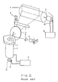
- FIG. 2 Conventional laser beam scanning apparatus utilised in a laser printer is shown in Figure 2 and employs, as a laser beam source, a semi-conductor laser 1 operable to turn on and off the generation of the laser beam in response to a laser modulation signal supplied according to an image signal.
- a semi-conductor laser 1 operable to turn on and off the generation of the laser beam in response to a laser modulation signal supplied according to an image signal.
- the laser beam scanning apparatus further comprises a collimator lens 2 for collimating the laser beam emitted from the semiconductor laser 1 to produce a substantially parallel laser beam, a polygonal mirror 3 rotatable at a predetermined rotational speed to deflect the laser beam passed by the collimator lens 2 in a primary scanning direction, and an f ⁇ lens 5 disposed between the polygonal mirror 3 and a photo-sensitive drum 4 for converging the laser beam reflected by the polygonal mirror 3 onto the photo-sensitive drum 4.
- a collimator lens 2 for collimating the laser beam emitted from the semiconductor laser 1 to produce a substantially parallel laser beam
- a polygonal mirror 3 rotatable at a predetermined rotational speed to deflect the laser beam passed by the collimator lens 2 in a primary scanning direction
- an f ⁇ lens 5 disposed between the polygonal mirror 3 and a photo-sensitive drum 4 for converging the laser beam reflected by the polygonal mirror 3 onto the photo-sensitive
- a first cylindrical lens 6 disposed between the collimator lens 2 and the polygonal mirror 3 and a second cylindrical lens 7 disposed between the f ⁇ lens 5 and the photo-sensitive drum 4 serve to compensate for inclination of the reflective surfaces of the polygonal mirror 3.
- a photo-detector 8 detects a starting position in the primary scanning direction for writing by the laser beam issued by the second cylindrical lens 7.
- the f ⁇ lens 5 and the cylindrical lens 7 constitute an optical converging arrangement for converging the beam reflected by the polygonal mirror 3 onto the surface of a photo-sensitive medium on the drum 4.
- a drive for the polygonal mirror 3 comprises a motor 9 of the DC type, a combination of a rotary encoder 13 and a photo-interrupter 14 for detecting the rate of rotation of the motor 9, and a motor driving circuit 15.
- a secondary scanning arrangement functions to rotate the photo-sensitive drum 4.
- the secondary scanning arrangement comprises a DC motor 10 for rotating the photo-sensitive drum 4, a combination of a rotary encoder 11 and a photo-interrupter 12 for detecting the rate of rotation of the DC motor 10, and a motor rotating or driving circuit 16.
- the driving circuit 15 and the driving circuit 16 have the same basic structure, and so only the driving circuit 15 will be explained below by way of example.
- FIG 3 is a block diagram of the conventional driving circuit 15.
- an oscillator circuit 91 utilising a quartz resonator generates an output signal, which is input into a frequency dividing circuit 92 to generate a reference clock signal.
- the photo-interrupter 14 co-operates with the rotary encoder 13, which is directly connected to a shaft of the motor 9, to supply a detection signal in synchronisation with the rotation of the motor.
- the detection signal is input into a waveform shaping circuit 96 effective to remove distortion from the waveform of the detection signal, an output signal of the waveform shaping circuit 96 being input into a phase comparator 93, which effects phase comparison between this output signal and the reference clock signal from the frequency dividing circuit 92.
- An output signal of the phase comparator 93 is input into an integrator circuit 94 to change the same into a voltage signal.
- the voltage signal of the integrator circuit 94 is then supplied to an amplifier 95 to generate the electric power needed for driving the motor 9.
- Such a circuit structure is known generally as a PLL control circuit.
- a pair of PLL control circuits are provided, independently from one another, for separately controlling the rate of rotation of the motor 9 for driving the polygonal mirror 3 and the motor 10 operative to rotate the photo-sensitive drum 4.
- the polygonal mirror 3 is rotated with a given rotational speed by means of a driving circuit 15.
- the rate of rotation of the polygonal mirror 3 is monitored by means of a combination of slits cut in the circumference of the rotary encoder 13 and the photo-interrupter 14.
- the photo-interrupter produces a pulse detection signal having a frequency proportional to the rate of rotation of the motor 9.
- the phase of this pulse signal is compared with that of the reference clock signal from the frequency dividing circuit 92 so as to effect the PLL control to rotate the motor 9 at a constant rate of rotation.
- the driving circuit 16 effects PLL control of the rate of rotation of the DC motor 10.
- the photo-sensitive drum 4 reaches approximately a predetermined angular position, the semi-conductor laser is turned on and the polygonal mirror 3 reflects the laser beam to scan the same in the primary scanning direction. After a given time interval from the moment when the scanned laser beam crosses the photo-sensor 8, the semi-conductor laser is turned on and off according to an input image signal to effect writing of the first line of the image. Following the writing of the first line, the photo-sensitive drum 4 continues to rotate at the constant rate of rotation and the photo-detector 8 detects the starting position for further writing in the primary scanning direction. Therefore, while the starting position for the writing of each line is aligned, the second and subsequent lines are written on the drum without duplication to reproduce thereby a two-dimensional image.
- the rotational speed of the photo-sensitive drum 4 is PLL controlled so as to equalise the pitch of the respective lines.
- the operation of the known laser beam scanning system is based on control of the rate of rotation of the photo-sensitive drum and there is no direct control of the angular position of the drum. Further, the rotation rate control for the polygonal mirror and the rotation rate control for the photo-sensitive drum are independent of each other. Consequently, the conventional system has drawbacks or problems such as:
- the present invention seeks to synchronise the primary or horizontal scanning of an optical beam and the secondary or vertical scanning of the optical beam with one another to permit accurate image reproduction.
- scanning apparatus comprising primary scanning means arranged to move an optical beam linearly in a primary scanning direction relative to a photo-sensitive medium, secondary scanning means arranged to move the optical beam substantially perpendicularly to the primary scanning direction in a secondary scanning direction relative to the photo-sensitive medium, whereby to scan the optical beam two-dimensionally relative to the photo-sensitive medium, and characterised by a control circuit having means for generating a common clock signal for controlling operation of both the primary and the secondary scanning means.
- a pulse driven motor may be utilised as a driving source of the secondary scanning means, and the common clock signal may be utilised in the generation of activating pulses for the pulse driven motor.
- laser beam scanning apparatus comprising means for emitting a laser beam, a mirror for reflecting the beam towards a photo-sensitive medium, the mirror being rotatable to deflect the laser beam linearly in a primary scanning direction, a main motor for rotating the mirror, means for shifting the laser beam relative to the photo-sensitive medium in a secondary scanning direction substantially perpendicular to the primary scanning direction whereby to scan the laser beam two-dimensionally relative to the photo-sensitive medium, the shifting means including a further motor, and characterised by control means for generating a common clock signal for controlling and driving the main motor and the further motor.
- Figure 1 is a diagrammatic view of a multi-colour projecting exposure system utilising a liquid crystal cell of the laser written type as an intermediate image medium or a photo-sensitive medium and employing laser beam scanning apparatus according to the invention.
- the multi-colour projecting exposure system comprises a projecting exposure system 62, an image writing system 61 including the laser beam scanning apparatus, and a developing system 63.
- the projecting exposure system 62 comprises a halogen lamp 29, a mirror 28 for collecting and reflecting light from the halogen lamp 29, a pair of condenser lenses 30 and 32 for converting light emitted from the halogen lamp 29 into a somewhat convergent light beam, a filter 31 disposed between the condenser lenses 30 and 32 for cutting off thermal energy contained in the light beam, and a half mirror 27 for selectively reflecting the light beam from the halogen lamp 29 to a liquid crystal cell on a rotating or rotary disc 33 and transmitting light reflected from the liquid crystal cell.
- a projecting lens 26 serves for projecting and focusing the light transmitted by the half mirror 27 onto a photo-sensitive film 21, which is mounted between a winding roller 22 for winding the photo-sensitive film 21, and a back tension roller 43 for uniformly tensioning the photo-sensitive film 21.
- the photo-sensitive film 21 may be a micro-capsule sheet produced by Meed Company of U.S.A.
- the micro-capsule sheet comprises PET film coated uniformly with three different kinds of micro-capsules, each composed of a thin film enclosure made of, for example, gelatin and containing three different colour formers, a1, a2 and a3 exhibiting cyan, magenta and yellow tones, respectively, and three different photo-sensitive compositions b1, b2 and b3 photo-sensitive to light having different wavelengths ⁇ 1, ⁇ 2 and ⁇ 3 corresponding to the respective colour formers and effective to change their own viscosity to immobilise the colour formers.
- the image writing system 61 comprises a laser beam primary scanning device including a semi-conductor laser (not shown), a polygonal mirror 41, a main motor 9 for rotating the polygonal mirror 41, and a reflective mirror 42.
- a bowl screw 38 drives a base 64, having the laser beam primary scanning device mounted thereon, in a secondary scanning direction, a pulse motor 39 rotating the bowl screw 38 by way of a flexible coupling 40.
- the base 64, bowl screw 38 and pulse motor 39 constitute a secondary scanning device.
- a rotary disk 33 ( Figure 4 shows its plan view) is rotated on a shaft 37 supported in bearings 36 by means of another pulse motor 34, and a worm wheel 35 for transmitting driving force from the pulse motor 34 to the shaft 37.
- the rotary disc 33 is provided with liquid crystal cells or panels 51, 52 and 53 for the exposure of yellow, cyan and magenta, respectively.
- the respective liquid crystal panels 51, 52 and 53 are disposed around the shaft 37 at equi-angular intervals of 120°.
- Each liquid crystal panel can have an image written thereon by means of a scanned laser beam.
- the developing system 63 comprises a feed roller 23 for a receiver sheet, which is uniformly coated with developer effective to react with the colour formers a1, a2 and a3 on the photo-sensitive film to cause colour development reaction.
- a pressure roller 24 presses the superposed photo-sensitive film 21 and receiver sheet against each other in response to the pressure of a spring 25 acting on the pressure roller 24.
- FIG 7 shows the circuitry of the image writing system 61, which circuitry includes a PLL control or feed back circuit for the motor 9 and a driving or feed forward circuit for the pulse motor 39.
- the PLL control circuit has the same structure as the conventional circuit shown in Figure 3 and includes an oscillator circuit 91 utilising a quartz resonator and generating an oscillating clock signal effective for producing a reference clock signal to regulate the rotation of the polygonal mirror.
- the pulse motor driving circuit shares the common oscillator circuit 91, and includes a frequency dividing circuit 71 for frequency dividing the oscillating clock signal output by the oscillator circuit 91 to reduce its frequency to a given value.
- a phase control circuit 72 controls the output signal from the frequency dividing circuit 71 to apply signal components with different phases to respective coils of the pulse motor 39 to set timings for the activation of the respective coils, a current amplifer 73 receiving the signal components from the circuit 72 to amplify the same to supply driving current pulses needed to actually drive the pulse motor 39.
- the secondary scanning device is initially moved to a home position as shown in Figure 6.
- the secondary scanning device commences movement in the secondary scanning direction under the control of the pulse motor 39.
- the pulse motor 39 has received the number n1 of the driving current pulses
- the writing of the yellow component of the colour image is started by scanning the laser beam two-dimensionally in the primary and secondary scanning directions.
- the pulse motor 39 has received the number n2 of the driving current pulses after the start of writing, the writing operation is stopped.
- the pulse motor 39 continues to receive the driving current pulses, and when it has received the number n3 of the pulses after the termination of the writing operation, the supply of pulses is terminated to stop the driving of the pulse motor 39.
- the yellow component of the colour image is written into the liquid crystal panel 51.
- a number n1 + n2 + n3 of reverse driving current pulses is applied to the pulse motor 39 to return the movable secondary scanning device to its home position. While this return operation of the laser beam secondary scanning device is taking place, the rotary disc 33 is angularly displaced to position the liquid crystal panel 52 for cyan exposure in place under the laser beam scanning apparatus. Thereafter, the cyan component of the colour image is written into the liquid crystal panel 52 for use in cyan exposure in a manner similar to the writing of the yellow component onto the first liquid crystal panel 51.
- the return of the secondary scanning device and the angular displacement of the rotary disc 33 are carried out to switch from the cyan related liquid crystal panel 52 to the magenta related liquid crystal panel 53. Then, by a similar writing operation, the magenta component of the colour image is written onto the liquid crystal panel 53.
- the liquid crystal panels are irradiated with light from the halogen lamp 29 and reflect the light onto the photo-sensitive film 21 to superpose the yellow, cyan and magenta colour image components on the photo-sensitive film 21 to compose a colour image.
- the rotary disc 33 is angularly displaced to position the yellow related liquid crystal panel 51 in alignment with the photo-sensitive film 21, and exposure of the film 21 by projection of the yellow colour image component onto the film 21 is carried out. After this exposure of the photo-sensitive film 21 is finished, the rotary disc 33 is angularly displaced and the cyan colour image component written in the liquid crystal panel 52 is projected onto the same portion of the photo-sensitive film 21 to superpose the yellow and cyan colour image components one on the other. In the same manner, the magenta colour image component written in the liquid crystal panel 53 is projected onto the film so that the yellow, cyan and magenta colour image components are superposed to compose the colour image.
- the starting positions of the image writing in each of the respective liquid crystal panels 51, 52 and 53 for use in the respective yellow, cyan and magenta exposures in both of the primary scanning direction and of the secondary scanning direction are made coincident by means of the motor 9 and by means of the pulse motor 39 based on the writing timing control shown in Figure 6. Accordingly, the yellow, cyan and magenta colour image components projected onto the photo-sensitive film 21 are perfectly matched to avoid colour dislocation.
- liquid crystal panels of the laser beam written type are used as an intermediate image writing medium.
- the image writing medium need not be liquid crystal panels, and other types of medium such as a photo-sensitive drum and a selenium plate can be used.
- the liquid crystal panels are switched by angular displacement of a rotary disc in the present embodiment, other methods and structures can be utilised to obtain the same function such as shifting the panels or their equivalent along a guide rail.
- the present invention while maintaining the conventional primary scanning arrangement and without providing an additional position sensor, enables the image to be written and reproduced from a desired position in the secondary scanning direction.
Landscapes
- Engineering & Computer Science (AREA)
- Multimedia (AREA)
- Signal Processing (AREA)
- Facsimile Scanning Arrangements (AREA)
- Mechanical Optical Scanning Systems (AREA)
- Exposure Or Original Feeding In Electrophotography (AREA)
- Fax Reproducing Arrangements (AREA)
- Dot-Matrix Printers And Others (AREA)
- Laser Beam Printer (AREA)
Applications Claiming Priority (2)
| Application Number | Priority Date | Filing Date | Title |
|---|---|---|---|
| JP196690/88 | 1988-08-06 | ||
| JP63196690A JPH0245169A (ja) | 1988-08-06 | 1988-08-06 | レーザ走査装置 |
Publications (2)
| Publication Number | Publication Date |
|---|---|
| EP0354739A2 true EP0354739A2 (fr) | 1990-02-14 |
| EP0354739A3 EP0354739A3 (fr) | 1990-08-29 |
Family
ID=16361975
Family Applications (1)
| Application Number | Title | Priority Date | Filing Date |
|---|---|---|---|
| EP89307960A Withdrawn EP0354739A3 (fr) | 1988-08-06 | 1989-08-04 | Appareil de balayage |
Country Status (3)
| Country | Link |
|---|---|
| US (1) | US5078463A (fr) |
| EP (1) | EP0354739A3 (fr) |
| JP (1) | JPH0245169A (fr) |
Families Citing this family (5)
| Publication number | Priority date | Publication date | Assignee | Title |
|---|---|---|---|---|
| JP2786027B2 (ja) * | 1991-06-28 | 1998-08-13 | シャープ株式会社 | 画像形成装置 |
| US5489985A (en) * | 1993-01-21 | 1996-02-06 | Matsushita Electric Industrial Co., Ltd. | Apparatus for inspection of packaged printed circuit boards |
| US5535061A (en) * | 1994-01-24 | 1996-07-09 | Juno Enterprises, Inc. | Rotary scanner |
| US5570183A (en) * | 1995-04-24 | 1996-10-29 | Ati Systems, Inc. | Apparatus for measuring optical characteristics of a surface in two dimensions using a moving light source |
| KR100199474B1 (ko) * | 1996-06-12 | 1999-06-15 | 김광호 | 전자사진 프린터의 장치의 용지 배면 오염 방지 제어방법 |
Family Cites Families (7)
| Publication number | Priority date | Publication date | Assignee | Title |
|---|---|---|---|---|
| US4302782A (en) * | 1977-03-10 | 1981-11-24 | Xerox Corporation | Reproduction scanning system having intermediate storage between input and output scanning stations |
| US4312590A (en) * | 1977-06-10 | 1982-01-26 | Eocom Corporation | Optical scanner and system for laser beam exposure of photo surfaces |
| FR2404272A1 (fr) * | 1977-09-23 | 1979-04-20 | Thomson Csf | Dispositif de reproduction d'images monochromes et systeme de teletransmission d'images utilisant un tel dispositif |
| US4139258A (en) * | 1978-04-05 | 1979-02-13 | The United States Of America As Represented By The Secretary Of The Navy | Laser scan converter |
| JPS5596916A (en) * | 1979-01-17 | 1980-07-23 | Canon Inc | Two-dimensional scanner |
| JPS5938724A (ja) * | 1982-08-28 | 1984-03-02 | Canon Inc | 光走査装置 |
| US4616132A (en) * | 1984-05-29 | 1986-10-07 | Eastman Kodak Company | Synchronization apparatus for scanner |
-
1988
- 1988-08-06 JP JP63196690A patent/JPH0245169A/ja active Pending
-
1989
- 1989-08-03 US US07/389,043 patent/US5078463A/en not_active Expired - Fee Related
- 1989-08-04 EP EP89307960A patent/EP0354739A3/fr not_active Withdrawn
Also Published As
| Publication number | Publication date |
|---|---|
| EP0354739A3 (fr) | 1990-08-29 |
| US5078463A (en) | 1992-01-07 |
| JPH0245169A (ja) | 1990-02-15 |
Similar Documents
| Publication | Publication Date | Title |
|---|---|---|
| US4122462A (en) | Image information recording apparatus | |
| KR19980081657A (ko) | 레이저 노광 유닛 | |
| JPH01127356A (ja) | 電子画像プリント装置 | |
| US5883746A (en) | Apparatus for beam splitting | |
| JPH0532734B2 (fr) | ||
| US4448513A (en) | Image information recording apparatus | |
| EP0354739A2 (fr) | Appareil de balayage | |
| US5049897A (en) | Method and apparatus for beam displacement in a light beam scanner | |
| JPS6111720A (ja) | 画像形成装置 | |
| US5706075A (en) | Exposure apparatus for controlling the duration of exposure operations according to compensated exposure data | |
| US5274398A (en) | Image forming device | |
| US4302096A (en) | Graphic forms overlay apparatus | |
| JPS6115119A (ja) | レ−ザプリンタ | |
| JP2001253114A (ja) | 画像露光記録装置における光量調整方法および装置 | |
| JP3327051B2 (ja) | 複数光ビーム走査装置 | |
| JPS62128277A (ja) | 熱転写式レ−ザビ−ムプリンタ | |
| JP2665219B2 (ja) | 半導体レーザアレイの出力制御装置 | |
| JPH04335669A (ja) | 画像露光装置 | |
| JPS59198076A (ja) | 画像形成装置 | |
| JPS6132029A (ja) | ホログラムスキヤナ制御装置 | |
| JP2775745B2 (ja) | 電子写真装置の帯電制御方法 | |
| JP3508143B2 (ja) | 画像記録装置 | |
| JPH03138180A (ja) | 記録装置 | |
| JPS63210910A (ja) | 画像形成装置 | |
| JPS63101813A (ja) | レ−ザ−ビ−ムプリンタ |
Legal Events
| Date | Code | Title | Description |
|---|---|---|---|
| PUAI | Public reference made under article 153(3) epc to a published international application that has entered the european phase |
Free format text: ORIGINAL CODE: 0009012 |
|
| AK | Designated contracting states |
Kind code of ref document: A2 Designated state(s): DE FR GB |
|
| PUAL | Search report despatched |
Free format text: ORIGINAL CODE: 0009013 |
|
| AK | Designated contracting states |
Kind code of ref document: A3 Designated state(s): DE FR GB |
|
| 17P | Request for examination filed |
Effective date: 19901228 |
|
| STAA | Information on the status of an ep patent application or granted ep patent |
Free format text: STATUS: THE APPLICATION HAS BEEN WITHDRAWN |
|
| 18W | Application withdrawn |
Withdrawal date: 19911207 |