EP0354779A2 - Bandmass - Google Patents
Bandmass Download PDFInfo
- Publication number
- EP0354779A2 EP0354779A2 EP89308091A EP89308091A EP0354779A2 EP 0354779 A2 EP0354779 A2 EP 0354779A2 EP 89308091 A EP89308091 A EP 89308091A EP 89308091 A EP89308091 A EP 89308091A EP 0354779 A2 EP0354779 A2 EP 0354779A2
- Authority
- EP
- European Patent Office
- Prior art keywords
- tape
- case
- tapeline
- lock
- blade
- Prior art date
- Legal status (The legal status is an assumption and is not a legal conclusion. Google has not performed a legal analysis and makes no representation as to the accuracy of the status listed.)
- Withdrawn
Links
Images



Classifications
-
- G—PHYSICS
- G01—MEASURING; TESTING
- G01B—MEASURING LENGTH, THICKNESS OR SIMILAR LINEAR DIMENSIONS; MEASURING ANGLES; MEASURING AREAS; MEASURING IRREGULARITIES OF SURFACES OR CONTOURS
- G01B3/00—Measuring instruments characterised by the use of mechanical techniques
- G01B3/10—Measuring tapes
- G01B3/1005—Means for controlling winding or unwinding of tapes
-
- G—PHYSICS
- G01—MEASURING; TESTING
- G01B—MEASURING LENGTH, THICKNESS OR SIMILAR LINEAR DIMENSIONS; MEASURING ANGLES; MEASURING AREAS; MEASURING IRREGULARITIES OF SURFACES OR CONTOURS
- G01B3/00—Measuring instruments characterised by the use of mechanical techniques
- G01B3/10—Measuring tapes
- G01B3/1005—Means for controlling winding or unwinding of tapes
- G01B3/102—Means for damping
-
- G—PHYSICS
- G01—MEASURING; TESTING
- G01B—MEASURING LENGTH, THICKNESS OR SIMILAR LINEAR DIMENSIONS; MEASURING ANGLES; MEASURING AREAS; MEASURING IRREGULARITIES OF SURFACES OR CONTOURS
- G01B3/00—Measuring instruments characterised by the use of mechanical techniques
- G01B3/10—Measuring tapes
- G01B3/1005—Means for controlling winding or unwinding of tapes
- G01B3/1007—Means for locking
- G01B2003/1017—Means for locking acting on the whole coil
-
- G—PHYSICS
- G01—MEASURING; TESTING
- G01B—MEASURING LENGTH, THICKNESS OR SIMILAR LINEAR DIMENSIONS; MEASURING ANGLES; MEASURING AREAS; MEASURING IRREGULARITIES OF SURFACES OR CONTOURS
- G01B3/00—Measuring instruments characterised by the use of mechanical techniques
- G01B3/10—Measuring tapes
- G01B3/1005—Means for controlling winding or unwinding of tapes
- G01B2003/1033—Means for activating the locking, braking or releasing of the tape, e.g. buttons
- G01B2003/1035—Means for activating the locking, braking or releasing of the tape, e.g. buttons by pivotal operation
Definitions
- the present invention relates in general to the field of hand tools and more particularly to a tape measure with a braking device used to control the retraction of the blade in a retractable blade tape measure.
- a tape measure of the type that will incorporate the present invention includes an outer case with a metal tape blade retractably mounted within the case.
- a retracting mechanism retracts the tape blade into the case.
- a hook at the end of the tape provides a stop for preventing the end of the tape from retracting inside the case.
- a clip allows the tape measure to be attached to a belt.
- a lock releasably secures the tape blade in the desired extended position.
- the lock typically includes a toggle switch with a lock shoe associated with the toggle switch. When one end of the toggle is depressed, the lock shoe is moved downward against the inside bottom of the case. Pushing the other end of the toggle releases the lock shoe, allowing the tape blade to freely retract into the case.
- An on-off brake for the winding drum of an encased tape rule comprises a double-headed non-rotatable push-button movable along the drum axis to and from a braking position in which a conical projection on the drum tightly frictionally engages a corresponding conical groove in one push-button.
- a gearless, open-faced, direct-drive, spring-rewound tape measure eliminates the need for a manual-rewind handle or gears to increase the spring tensioning force.
- a spiral spring is retained within a spring-retaining disk which is revolvable about a hub.
- the hub may be attached to the cover plate and the spring tension adjusted by revolving the cover plate which the spring-retaining disk remains stationary.
- the cover plate may be coupled through an input disk to revolve the spring-retaining disk and to adjust the tension of a spring which is retained within a spring-retaining well of the spring-retaining disk.
- the cover plate is restricted from revolving by compression lock rings which sandwich the cover plate.
- the tape measure may include a brake to allow holding the tape in an unwound condition.
- a tape measure includes a housing having an opening and a measuring tape coiled therein including a free end having a hook member attached thereto.
- the free end of the tape extends through the opening in the housing and a braking lever is pivotally mounted to the housing with its front end adjacent the opening in position to engage the hook member when the tape is in a retracted position.
- the front end of the lever is normally biased into engagement with the tape, at the housing opening, by a spring, thereby to prevent movement of the tape.
- a pivot member for absorbing the shock of impact when the hook member engages the front end of the lever during retraction of the tape includes a pivot pin for pivotally mounting the lever to the housing and a shock absorbing element of a deformable, resilient material adjacent the pivot pin for absorbing the shock.
- U.S. Patent 4,439,927 to Larry E. Elliott patented April 3, 1984 discloses a "Tape Measure”.
- a coiled metal disposed within the casing which may be retracted or withdrawn through a slot in the front of the casing.
- a consumable marker and a scriber are disposed within the casing immediately forward of and along side of the slot through which the coiled tape is withdrawn. Either the consumable marker or the scriber may be positioned via manual actuating means to mark an object being measured at a preselected point along the length of the extended tape.
- Braking means are disposed within the casing which, when actuated, engage the tape and lock it into position relative to the casing.
- the braking mechanism is automatically activated when either the consumable marker or the scriber is positioned for marking the object being measured.
- the braking means may be activated without marking or engraving the object being measured.
- a plurality of feed segments disposed within the casing operate to insure that the marker continues to contact the workpiece even though its length is diminished over a period of usage.
- a bumper indicator which is adapted to be used on the tape rule of a measuring tool.
- the bumper indicator is a one piece resilient member having front and rear surfaces and a transverse slit whose configuration is selected to be generally complimentary to the cross sectional configuration of the tape rule on which it is mounted, thereby to frictionally engage and slidably receive the tape rule.
- the bumper has top and bottom edges and the rear surface of the bumper facing the casing for the tape measure is chamfered from a position below the slit to the bottom edge. The bumper serves to cushion recoil of the tape, as well as to provide an indicator along the tape when it is extended to facilitate repetitive measurements.
- the present invention provides a measuring tape comprising a casing having an opening; a tape coilable in the casing and being moveable in and out of said opening; motor means for retracting the tape into the casing; lock means for movement from a position in which it is out of engagement with the tape to a position in which it engages the tape, locks the tape and holds it in a particular position of extension out the opening; and means for braking the tape when the lock means releases the tape and the tape is returned by the motor means.
- the braking device controls retraction of the tape blade in a retractable blade tape measure.
- the tape measure includes a tape measure case and a coiled tapeline or tape blade inside the case. If desired, a lock shoe and lock button may be utilized to fix the tapeline in a specific extended position. One end of the lock button is positioned adjacent the lock shoe and tape.
- Movement of the lock button and lock shoe allows the blade to be locked in the extended position.
- a motor mechanism retracts the tape blade into the case.
- the braking device contacts the coiled tape blade inside the case before the end of the tape blade strikes the case.
- the braking device reduces or stops retraction of the tape blade before the end of the tape blade strikes the case.
- the retractable tape measure 10 includes a casing 11 comprising a pair of generally box-like sections 11A and 11B. The sections 11A and 11B are secured together by screws 12. A tape blade 13 extends from case 11 through an opening 14 in the lower front portion of case 11.
- a tape retraction means retracts the tape blade 13 into case 11 for convenient storage.
- Most tape measures use a spring retraction system to retract the blade tape.
- U.S. Patents Nos. 3,578,259; 4,479,617; and 4,527,334 generally describe such retraction systems.
- the present invention may be employed with other retraction systems.
- the tape retraction means generally applies a retracting force when the tape blade 13 is pulled out of the case 11.
- a lock means is utilized to overcome the retracting force of the tape retraction means.
- An example of a lock means is shown in U.S. Patent No. 3,578,259 to Charles Zelnick for "Coilable Rule Locking Mechanism” patented May 11, 1971.
- the extended portion of the tape blade 13 that has been pulled from the case 11 will be locked in place so that the user will not have to hold the tape in an extended position. This frees the user while taking measurements.
- a hook 15 at the end of the tape blade 13 provides a stop for preventing the end of tape blade from retracting inside the case 11. Problems have been encountered resulting in damages to the tape blade when the hook 15 strikes the case with excessive force when it is being retracted into the case. As the tape blade is being retracted into the case by retracting mechanism, a substantial amount of inertia is built up. This inertia causes the hook 15 at the tape blade to strike the case with substantial force. Excessive tape blade failures may result from the excessive whipping of the tape blade attachment against the tape housing. This is particularly true today because the length of the tape blades have been increased with modern tape measures.
- the tape blade 13 has been extended to a substantial length.
- the tape blade 13 When the tape blade 13 is being retracted in the case 11 and the hook end 15 approaches the opening 14 as illustrated in Figure 1, the tape blade may be travelling at a substantial speed. This can cause the blade to whip and the hook 15 to strike the case with substantial force.
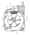
- the case 11 of tape measure 10 is configured and dimensioned to house a state of the art tape retraction means 16.
- the coiled tape blade 13 is located inside case 11.
- a lock button 17 and lock shoe 24 are connected to case 11.
- the case 11 includes generally flat sections 11A and 11B as shown in Figures 1 and 2.
- the case 11 includes an inclined front wall section 18, top wall section 19, rear wall section 20, and bottom wall section 21.
- the tapeline 13 is normally coiled in the case 11.
- the tapeline 13 has a leading end that extends outwardly through slotted opening 14 formed in the casing front wall section 18.
- the tape hook 15 is secured to the front end of the tapeline 13 in the usual manner.
- Tapeline 13 is wound on a winding drum 22 and is adapted to be retracted by the spring motor retracting means 16.
- the spring motor retracting means 16 is secured to the tapeline 13 at its inner end which is received within a slot provided in the casing center post in the usual manner.
- the vertically reciprocating lock shoe 24 is provided with a tapeline engaging pad for engaging the tapeline 13.
- the pad depresses the tapeline 13 to form a locking engagement. Movement of the lock shoe 24 is accomplished by movement of the lock button 17.
- Lock button 17 pivots about the Pin 26. When the lower portion of the lock button 17 is pressed, the curved ramp surface 28 forces the lock shoe 24 downward into the tape engaging position.
- the brake means 27 is at the upper end of the lock button 17 and is an extension 27 that projects inward toward the coiled tape blade 13.
- the lock button 17 is moved to the non-locking position. In this position, the motor 16 will rotate drum 22 and tapeline 13 will build up on the coil until it contacts the brake or extension 27 at which time it will provide a braking force stopping the tapeline 13 before the hook 15 at the end of tapeline 13 strikes the case 11.
- the lock button can be pressed at its lower end to move the extension away from the coiled tapeline and allow it to fully retract into the case 11.
- the toggle lock button 17 and lock shoe 24 are normally maintained out of clamping engagement with the tapeline 13.
- the toggle button 17 is pressed at its lower end to revolve it clockwisely about the pivot pin 26 and move the lock shoe 24 sharply down into engagement with the tapeline 13.
- locking shoe 24 is immediately released to return upwardly. This allows the tapeline to be retracted into the case 11.
- the retracting mechanism and the portion of the tape blade already retracted into the case build up inertia.
- This inertia can on occasion cause the hook 15 at the end of the tape blade to strike the case with substantial force when the blade is fully retracted.
- the hook and the adjacent portion of the tape blade can be damaged by this force.
- the upper end of the lock button 17 includes an extension 27 that projects inward toward the coiled tape blade 13.
- the lock button 17 In order to retract the tapeline 13, the lock button 17 is moved to the non-locking position. In this position, the tapeline is retracted and will build up on the coil until it contacts the extension 27. The operator can hold the upper portion of button 17 in the inwardly extending position with the extension 27 closest to the coiled tape. When the tapeline 13 contacts extension 27, extension 27 will provide a braking force stopping the tapeline 13 before the hook 15 at the end of tapeline 13 strikes the case 11. The upper portion of button 17 is then released allowing the extension 27 to move away from the coiled tape and the tapeline can be fully retracted into case 11. The lock button can be pressed at its lower end to move the extension 27 away from the coiled tapeline and allow it to fully retract into the case 11.
- FIG. 4 A sectional view of a retractable tape measure 30 is shown.
- the case 31 of tape measure 30 is configured and dimensioned to house a state of the art tape retraction means 39.
- the coiled tape blade 32 is located inside case 31.
- a lock button 36 and lock shoe 33 are connected to case 31.
- the case 31 includes an inclined front wall section, top wall section, rear wall section and bottom wall section.
- the tapeline 32 is normally coiled in the case 31.
- the tapeline 32 has a leading end that extends outwardly through the slotted opening formed in the casing front wall section.
- the tape hook 34 is secured to the front end of the tapeline 32 in the usual manner.
- Tapeline 32 is wound on a winding drum and is adapted to be retracted by the spring motor retracting means 39.
- the spring motor retracting means 39 is secured to the tapeline 32 at its inner end which is received within a slot provided in the casing center post in the usual manner.
- the lock shoe 33 is provided with a tapeline engaging pad for engaging the tapeline 32.
- the pad depresses the tapeline 32 to form a locking engagement. Movement of the lock shoe 33 is accomplished by movement of the lock button 36.
- Lock button 36 pivots about the pin 35. When the lower portion of the lock button 36 is pressed, the curved ramp surface 37 forces the lock shoe 33 downward into the tape engaging position.
- the brake 40 is a button 40 located on the top of case 31.
- the lower portion of the brake or button 40 projects inward through casing 31 toward the coiled tape blade 13.
- the lock button 36 is moved to the non-locking position. In this position, the motor 39 will rotate and the tapeline 32 will build up on the coil until it contacts the bottom of the brake or button 40 at which time it will provide a braking force stopping the tapeline 32 before the hook 34 at the end of tapeline 32 strikes the case 31.
- the brake or button 40 is released to allow the brake or button 40 to move away from the coiled tapeline 32 and allow it to fully retract into the case 31 as shown in Figure 4.
- the toggle lock button 36 and lock shoe 33 are normally maintained out of clamping engagement with the tapeline 32.
- the toggle button 36 is pressed at its lower end to revolve it clockwisely about the pivot pin 35 and move the lock shoe 33 sharply down into engagement with the tapeline 32.
- the toggle button 36 is pivoted by pressing its upper portion 38, locking shoe 33 is immediately released to return upwardly. This allows the tapeline 32 to be retracted into the case 31.
- the retracting mechanism and the portion of the tape blade already retracted into the case build up inertia.
- This inertia can, on occasion, cause the hook 34 at the end of the tape blade to strike the case with substantial force when the blade is nearly fully retracted.
- the hook and the adjacent portion of the tape blade can be damaged by this force.
- the brake or button 40 includes a lower portion that projects inward through the case 31 toward the coiled tape blade 32.
- the lock button 36 is moved to the non-locking position. In this position, the tapeline is allowed to retract and will build up on the coil until it contacts the brake or button 40.
- the operator hold button is in a position where it is fully extended into the case 31.
- the tapeline 32 When the tapeline 32 contacts the brake or button 40, it will provide a braking force stopping the tapeline 32 before the hook 34 at the end of tapeline 32 strikes the case 31.
- the button 40 can be released to move it away from the coiled tapeline and allow the tapeline to fully retract into the case.
- FIG. 5 a sectional view of yet another embodiment of a retractable tape measure 41 constructed in accordance with the present invention is shown.
- the case 43 of tape measure 41 is configured and dimensioned to house a state of the art tape retraction means 58.
- the coiled tape blade 55 is located inside case 43.
- a lock button 50 and lock shoe 53 are connected to case 43.
- the case 43 includes generally flat side sections.
- the case 43 includes an inclined front wall section 49, top wall section 42, rear wall section 44, and bottom wall section 46.
- the tapeline 55 is normally coiled in the case 43.
- the tapeline 55 has a leading end that extends outwardly through slotted opening 56 formed in the casing front wall section 49.
- the tape hook 57 is secured to the front end of the tapeline 55 in the usual manner.
- Tapeline 55 is wound on a winding drum 59 and is adapted to be retracted by the spring motor retracting means 58.
- the spring motor retracting means 58 is secured to the tapeline 55 at its inner end which is received within a slot provided in the casing center post in the usual manner.
- a vertically reciprocating lock shoe 53 is provided in vertical alignment with recess portions in the case 43.
- the lock shoe 53 is provided with a tapeline engaging pad for engaging the tapeline 55.
- the pad depresses the tapeline 55 to form a locking engagement. Movement of the lock shoe 53 is accomplished by movement of the lock button 50.
- Lock button 50 pivots about the pin 51. When the lower portion of the lock button 50 is pressed, the curved ramp surface 52 forces the lock shoe 53 downward into the tape engaging position.
- the upper end of the lock button 50 contacts a brake or retract control unit 61 that is located above the lock button 50.
- the brake retract control unit 61 pivots about pin 60 from an inner position adjacent the coiled tape to an outer position nearer the front 49 of case 43.
- the lock button 50 is moved to the non-locking position.
- the operator can maintain inward pressure on the upper portion of lock button 50 maintaining brake or retract control unit 61 in its innermost position.
- the motor 58 will rotate drum 59 and tapeline 55 will build up on the coil until it contacts the retract control unit 61 at which time it will provide a braking force stopping the tapeline 55 before the hook 57 at the end of tapeline 55 strikes the case 43.
- the lock button can be pressed at its lower end to move the upper end of lock button 50 and the brake or retract control unit 61 away from the coiled tapeline and allow it to fully retract into the case 43.
- the toggle lock button 50 and the lock shoe 53 are normally maintained out of clamping engagement with the tapeline 55.
- the toggle button 50 is pressed at its lower end to revolve it clockwisely about the pivot pin 51 and move the lock shoe 53 sharply down into engagement with the tapeline 55.
- the toggle button 50 is pivoted by pressing its upper portion, locking shoe 53 is immediately released to return upwardly. This allows the tapeline to be retracted into the case 43.
- the operator can maintain pressure on the upper end of the lock button 50 which contacts retract control unit 61 that projects inward toward the coiled tape blade 55.
- the lock button 50 In order to retract the tapeline 55, the lock button 50 is moved to the non-locking position. The operator continues to maintain pressure on the upper portion of lock button 50. In this position, the tapeline is retracted and will build up on the coil until it contacts the brake or retract control unit 61.
- the tapeline 55 When the tapeline 55 contacts the brake or retract control unit 61, it will provide a braking force stopping the tapeline 55 before the hook 57 at the end of tapeline 55 strikes the case 43.
- the upper portion of button 50 is then released allowing the retract control unit 61 to move away from the coiled tape and the tapeline can be fully retracted into case 43.
- the lock button can be pressed at its lower end to move the unit 61 away from the coiled tapeline and allow it to fully retract into the case 43.
Landscapes
- Physics & Mathematics (AREA)
- General Physics & Mathematics (AREA)
- Tape Measures (AREA)
- Basic Packing Technique (AREA)
- Braking Arrangements (AREA)
- Cable Accessories (AREA)
- Manufacturing Of Electric Cables (AREA)
Applications Claiming Priority (2)
| Application Number | Priority Date | Filing Date | Title |
|---|---|---|---|
| US07/231,292 US4903912A (en) | 1988-08-12 | 1988-08-12 | Tape measure braking device |
| US231292 | 1988-08-12 |
Publications (2)
| Publication Number | Publication Date |
|---|---|
| EP0354779A2 true EP0354779A2 (de) | 1990-02-14 |
| EP0354779A3 EP0354779A3 (de) | 1990-12-27 |
Family
ID=22868599
Family Applications (1)
| Application Number | Title | Priority Date | Filing Date |
|---|---|---|---|
| EP19890308091 Withdrawn EP0354779A3 (de) | 1988-08-12 | 1989-08-09 | Bandmass |
Country Status (8)
| Country | Link |
|---|---|
| US (1) | US4903912A (de) |
| EP (1) | EP0354779A3 (de) |
| AU (1) | AU3942089A (de) |
| CA (1) | CA1307106C (de) |
| DK (1) | DK392689A (de) |
| ES (1) | ES2014854A6 (de) |
| FI (1) | FI893669A7 (de) |
| NO (1) | NO893129L (de) |
Cited By (2)
| Publication number | Priority date | Publication date | Assignee | Title |
|---|---|---|---|---|
| WO2001018485A1 (de) * | 1999-09-02 | 2001-03-15 | Stefan Weiss Messwerkzeugfabrik | Rollbandmass mit bremseinrichtung |
| DE10229437A1 (de) * | 2002-07-01 | 2004-01-15 | Weiss Messwerkzeuge Gmbh | Messinstrument |
Families Citing this family (16)
| Publication number | Priority date | Publication date | Assignee | Title |
|---|---|---|---|---|
| US5245761A (en) * | 1992-02-25 | 1993-09-21 | Arthur Waldherr | Locking mechanism for retractable tape |
| US5395069A (en) * | 1994-08-09 | 1995-03-07 | Chen; Chi-Chung | Two-stage brake device of a tape measure |
| US5791581A (en) * | 1996-11-27 | 1998-08-11 | The Stanley Works | Tape rule blade hook shock absorbers |
| USD390794S (en) | 1997-03-18 | 1998-02-17 | John Clement Coetzee | Tape measure with built in square and ruler |
| US5794357A (en) * | 1997-07-31 | 1998-08-18 | Cooper Industries, Inc. | One piece compound lock for tape measure |
| US5829154A (en) * | 1997-08-07 | 1998-11-03 | Lin; Lin Ping | Tape measure with flexible braking strips |
| DE29718228U1 (de) * | 1997-10-14 | 1997-12-18 | Li, Shih Lin, Taipeh/T'ai-pei | Meßbandanordnung |
| CA2227913A1 (en) * | 1998-01-27 | 1999-07-27 | Shih Lin Li | A tape measure structure with improved brake device |
| US6085433A (en) * | 1998-10-15 | 2000-07-11 | Li; Shinh Lin | Tape measure with innovated brake structure |
| US6276071B1 (en) * | 1999-08-14 | 2001-08-21 | Olympia Group, Inc. | Tape measure with tape braking control mechanism |
| US6295740B1 (en) | 2000-03-11 | 2001-10-02 | Bradley E. Mitchell | Power-movement measuring tape |
| USD441309S1 (en) | 2000-08-24 | 2001-05-01 | The L.S. Starrett Company | Tape measure |
| US6595451B1 (en) * | 2002-01-29 | 2003-07-22 | Komelon Corporation | Tape locking device for tape measure |
| US20050011082A1 (en) * | 2003-07-14 | 2005-01-20 | Smith Michael J. | Tape measure device |
| US8953327B1 (en) * | 2011-05-26 | 2015-02-10 | iBlaidZ, Inc. | Self-winding membrane device |
| KR102003160B1 (ko) * | 2018-06-12 | 2019-07-23 | 박인호 | 자동 잠금과 자동 멈춤 기능을 구비한 줄자 |
Family Cites Families (18)
| Publication number | Priority date | Publication date | Assignee | Title |
|---|---|---|---|---|
| US2250171A (en) * | 1940-08-26 | 1941-07-22 | Hugh A Wilkins | Adjustable dog leash |
| US2460082A (en) * | 1946-10-05 | 1949-01-25 | Schick Inc | Electric cord reel |
| US3482798A (en) * | 1966-04-16 | 1969-12-09 | Tajima Seisakusho Kk | Tape measure means |
| US3578259A (en) * | 1968-05-13 | 1971-05-11 | Cooper Ind Inc | Coilable rule locking mechanism |
| FR1587450A (de) * | 1968-10-10 | 1970-03-20 | ||
| US3889897A (en) * | 1973-09-26 | 1975-06-17 | Stanley Works | Coilable tape measuring device having a self-regulating speed control mechanism |
| US3942738A (en) * | 1974-09-16 | 1976-03-09 | The Stanley Works | Coilable rule |
| FR2344811A1 (fr) * | 1976-03-18 | 1977-10-14 | Stanley Mabo | Instrument de mesure lineaire |
| FR2346677A1 (fr) * | 1976-03-29 | 1977-10-28 | Stanley Mabo | Mesure roulante avec un dispositif de blocage du ruban |
| JPS5624884Y2 (de) * | 1977-06-23 | 1981-06-11 | ||
| US4288923A (en) * | 1979-12-19 | 1981-09-15 | Roe International, Inc. | Tape measure |
| FR2506450A1 (fr) * | 1981-05-19 | 1982-11-26 | Stanley Mabo | Dispositif de freinage d'un ruban de mesure metallique |
| US4479617A (en) * | 1982-10-13 | 1984-10-30 | Cooper Industries, Inc. | Tape measure construction incorporating a modified tape hook bumper |
| US4449302A (en) * | 1982-12-07 | 1984-05-22 | The Stanley Works | Power returnable coilable rule with improved blade locking assembly |
| US4439927A (en) * | 1983-01-13 | 1984-04-03 | Elliott Larry E | Tape measure |
| US4730783A (en) * | 1983-09-30 | 1988-03-15 | Spencer Products Company | Tape measure |
| US4527334A (en) * | 1983-09-30 | 1985-07-09 | Cooper Industries, Inc. | Power return tape |
| US4603481A (en) * | 1984-09-19 | 1986-08-05 | Irwin Measuring Tool Co. | Bumper indicator |
-
1988
- 1988-08-12 US US07/231,292 patent/US4903912A/en not_active Expired - Lifetime
-
1989
- 1989-08-02 FI FI893669A patent/FI893669A7/fi not_active IP Right Cessation
- 1989-08-03 NO NO89893129A patent/NO893129L/no unknown
- 1989-08-04 CA CA000607648A patent/CA1307106C/en not_active Expired - Fee Related
- 1989-08-08 AU AU39420/89A patent/AU3942089A/en not_active Abandoned
- 1989-08-08 ES ES8902826A patent/ES2014854A6/es not_active Expired - Fee Related
- 1989-08-09 EP EP19890308091 patent/EP0354779A3/de not_active Withdrawn
- 1989-08-10 DK DK392689A patent/DK392689A/da not_active Application Discontinuation
Cited By (2)
| Publication number | Priority date | Publication date | Assignee | Title |
|---|---|---|---|---|
| WO2001018485A1 (de) * | 1999-09-02 | 2001-03-15 | Stefan Weiss Messwerkzeugfabrik | Rollbandmass mit bremseinrichtung |
| DE10229437A1 (de) * | 2002-07-01 | 2004-01-15 | Weiss Messwerkzeuge Gmbh | Messinstrument |
Also Published As
| Publication number | Publication date |
|---|---|
| US4903912A (en) | 1990-02-27 |
| AU3942089A (en) | 1990-02-15 |
| FI893669A0 (fi) | 1989-08-02 |
| ES2014854A6 (es) | 1990-07-16 |
| DK392689A (da) | 1990-06-13 |
| FI893669L (fi) | 1990-02-13 |
| DK392689D0 (da) | 1989-08-10 |
| EP0354779A3 (de) | 1990-12-27 |
| FI893669A7 (fi) | 1990-02-13 |
| NO893129L (no) | 1990-02-13 |
| NO893129D0 (no) | 1989-08-03 |
| CA1307106C (en) | 1992-09-08 |
Similar Documents
| Publication | Publication Date | Title |
|---|---|---|
| US4903912A (en) | Tape measure braking device | |
| US4603481A (en) | Bumper indicator | |
| USRE39719E1 (en) | Rule assembly with increased blade standout | |
| US6996915B2 (en) | Tape measure apparatus which can be used as a marking gauge and/or compass | |
| EP1074812B1 (de) | Messband mit Dose | |
| US4998356A (en) | Carpenter's tape measure with push on-push off locking mechanism | |
| US4949458A (en) | Knife | |
| US4856726A (en) | Tape measure | |
| US3802083A (en) | Marker and stop accessory for extensible measuring tapes | |
| US5575077A (en) | Extendable tape measure | |
| US6449866B1 (en) | Rule assembly with improved blade hook | |
| US6249986B1 (en) | Rule assembly with protective film | |
| US3731389A (en) | Tape measuring device | |
| US6115933A (en) | Tape measure with decelerating mechanism | |
| US6282808B1 (en) | Rule assembly with hook bend protection | |
| US5743021A (en) | Digital length gauge | |
| US6612046B1 (en) | Marking device | |
| US5515617A (en) | Measuring, marking, and cutting tool | |
| US6513261B2 (en) | Measuring and scribing device | |
| GB2114094A (en) | Tape measure locking device | |
| EP2784437B1 (de) | Rollmaßband-Verriegelungssystem | |
| WO2005085747A1 (en) | Tape measures providing access to the spooled blade | |
| US5857261A (en) | Sophisticated structure for a tape measure | |
| EP0393892A2 (de) | Behälter für ein Rollmassband | |
| GB1601480A (en) | Measuring tapes |
Legal Events
| Date | Code | Title | Description |
|---|---|---|---|
| PUAI | Public reference made under article 153(3) epc to a published international application that has entered the european phase |
Free format text: ORIGINAL CODE: 0009012 |
|
| AK | Designated contracting states |
Kind code of ref document: A2 Designated state(s): AT BE CH DE FR GB IT LI NL SE |
|
| PUAL | Search report despatched |
Free format text: ORIGINAL CODE: 0009013 |
|
| AK | Designated contracting states |
Kind code of ref document: A3 Designated state(s): AT BE CH DE FR GB IT LI NL SE |
|
| 17P | Request for examination filed |
Effective date: 19910607 |
|
| STAA | Information on the status of an ep patent application or granted ep patent |
Free format text: STATUS: THE APPLICATION HAS BEEN WITHDRAWN |
|
| 18W | Application withdrawn |
Withdrawal date: 19911106 |
|
| R18W | Application withdrawn (corrected) |
Effective date: 19911106 |
|
| R18W | Application withdrawn (corrected) |
Effective date: 19911108 |