EP0354816A2 - Strichkodedruck - Google Patents
Strichkodedruck Download PDFInfo
- Publication number
- EP0354816A2 EP0354816A2 EP89308207A EP89308207A EP0354816A2 EP 0354816 A2 EP0354816 A2 EP 0354816A2 EP 89308207 A EP89308207 A EP 89308207A EP 89308207 A EP89308207 A EP 89308207A EP 0354816 A2 EP0354816 A2 EP 0354816A2
- Authority
- EP
- European Patent Office
- Prior art keywords
- ink
- label
- ink jet
- unit
- Prior art date
- Legal status (The legal status is an assumption and is not a legal conclusion. Google has not performed a legal analysis and makes no representation as to the accuracy of the status listed.)
- Granted
Links
Images


Classifications
-
- G—PHYSICS
- G06—COMPUTING OR CALCULATING; COUNTING
- G06K—GRAPHICAL DATA READING; PRESENTATION OF DATA; RECORD CARRIERS; HANDLING RECORD CARRIERS
- G06K1/00—Methods or arrangements for marking the record carrier in digital fashion
- G06K1/12—Methods or arrangements for marking the record carrier in digital fashion otherwise than by punching
Definitions
- This invention relates to bar code printing and, more particularly but not exclusively, is concerned with the generation of indicia which constitute the bar code.
- Bar codes are now widely used for ready identification of products at goods-in and check-out locations associated, for example, with retail trading. They facilitate the use of fully automatic in-and-out systems and, in some instances, do away with the need for price labels on the products. Many supermarkets stock 25,000 to 30,000 items for sale, however, and do not have sufficient shelf space to allocate all of these items to a particular position; as a result, even if there is a bar code on such products, there is still a need for price marking. Nevertheless, the use of a bar code scanning system to identify the goods may reduce labour requirements significantly and thus produce considerable savings.
- a retail outlet In order to apply price labels to items already carrying a bar code, and to add a bar code to those products which are not coded at source, it is common for a retail outlet to use one or more label printers. These may be hand-held or fixed in position. Typically, three stationary printers may be used by up to ten people. Strips of labels will be printed and taken to the product and either applied by hand or with a dispenser. Some retailers consider that it is more economical for each operative to have his own hand-held bar code label printer.
- a national bar code has been allocated to a given product, this will normally be used by the retailer if no manufacturer's bar code is present. For products where no such national bar code has been allocated, it is up to the retailer to decide on his own bar code number. Typically, this number might be based on the numbering system used by the retailer before the introduction of bar code scanning to his store. In practice, the person generating bar codes with a printer will have with him source material which indicates the nature of the bar code for each product where a label is required.
- Hand-held labelling machines typically comprise a housing which is arranged to store a label supply roll; a printing unit; and a keyboard for inputting data.
- a machine When such a machine is used to print bar code labels, an operative will input the bar code number via the keyboard, which then activates a label feed mechanism and the printing unit to apply the requested bar code to one of the labels on the supply roll.
- the label feed mechanism moves the supply roll so that the printed label is accessible for application to the appropriate goods item.
- thermographic printing head The printing unit in a typical bar code printer or labelling machine is based on a thermographic printing head. This is conventionally used in conjunction with thermographic paper. This need for a special quality of paper in conjunction with the high peak currents needed to heat the image elements of the thermographic print head tend to limit the versatility of bar code printers and to limit the operating time where the power supply for the printer is an internal battery.
- thermographic printing heads it may also be possible to simplify the electrical circuitry associated with the printer since there will be less need to take into account hysteresis effects (temperature against time) resulting from sequential use of the same dot matrix element on the print head.
- a device suitable for printing bar codes which comprises a housing, means for holding a label supply roll, printing means for applying indicia to a label, means for supplying data to determine the nature of the indicia printed on the label, and means for supplying electrical energy to operate the device, characterised in that said print unit is (a) an electrographic or xerographic image forming unit; or an ink jet printer; or a non-thermal contact print assembly.
- the print unit is an electrographic print unit
- it may comprise an array of ion sources located closely adjacent to an electrographic drum which is able to receive and hold electrical charge resulting from ions impinging on the surface of the drum.
- a predetermined array of ion generating units is operated so as to transfer to the drum a predetermined pattern of electrical charge.
- the drum is then rotated to come into contact with a label, which is then coated with toner particles which adhere to charged regions only. The toner particles are then fused to generate the desired image on the label.
- a xerographic print head functions in a manner similar to that described above, except that instead of an array of ion generating units, there is employed an array of light sources, for example light emitting diodes, adjacent to an amorphous silicon photoconductor drum.
- the generation of an image from the latent image held on the drum surface involves toner and a toner fusing system.
- Such a xerographic print unit may be robust, compact and possess a long operating life.
- the print unit comprises an ink jet printer
- this may operate according to any acceptable technology, for example as a bubble ink jet or as a solid ink jet.
- a heating element is located in the side wall of a nozzle containing liquid ink.
- the heater is energised so that ink in contact with the heater is warmed abruptly, resulting in rapid evaporation of the liquid ink thereby generating rapidly inflating bubble.
- the bubble expands across the width of the nozzle interior, it expels a liquid droplet from the nozzle orifice.
- the heater element is de-energised, the ink bubble deflates and either vanishes or remains only as a very small, vestigial bubble.
- it is the supply of ink can be arranged so that there is substantially no drop in supply pressure during extended operation of the printer.
- the printer is to be used upside down, then the relative position of the ink reservoir and the print head will be reversed; thus a system originally intended to operate with the ink reservoir below the print head will have to be capable of functioning with the reservoir above the print head, and vice versa.
- this is achieved by ensuring that the tubes which connect the ink reservoir to the print head are of such a small diameter that the capillary forces acting between the ink and the internal surfaces of the tubes are large compared to the effect of gravity.
- Another approach is to supply the liquid ink to the print head by means of a positive displacement device such as a peristaltic pump. The delivery of ink by the pump is then synchronised with the demand for ink by the print head.
- Plain paper labels may be used with such an ink jet, and the consumption of ink is low since none is wasted during the printing operation.
- ink jet printer is the so-called solid or hot melt ink jet.
- a wax-based ink normally solid
- the print head ejects droplets of the molten ink on demand.
- a plug of solid ink is contained within a cylinder against which a plunger is biassed. That end of the cylinder opposite the plunger is provided with a heating element which is generally located about an outlet conduit for molten ink.
- the heater in the end face of the cylinder is operated so as to melt a predetermined amount of the solid ink which then travels along the outlet conduit to the print head, from which it is ultimately ejected.
- the interior of the outlet conduit forms a liquid reservoir.
- Solid ink jet printers usually require a warm-up period in which the liquid reservoir fills and reaches equilibrium.
- the print unit comprises non-thermal contact print assembly
- this will generally be a mechanical contact system, and is preferably in the form of an array of marker elements, for example fibre markers, in contact with an ink source.
- marker elements can be arranged in a lateral array with adjacent markers being in contact with one another.
- the marker elements are moved upwardly and downwardly so as to break and make contact with the substrate on which indicia are to be printed. Control of such movement is preferably achieved by means of a cam wheel in contact with the ends of the marker elements remote from the substrate, although other mechanical or electromechanical systems may be used if desired.
- Such a print unit functions, in essence, as an array of pens each of which is in contact with its neighbour.
- An alternative arrangement (which does not require contact between adjacent writing elements) involves a non-linear array in which adjacent marker elements are staggered. Like a linear arrangement of contiguous marker elements, the staggered arrangement also permits the generation of broad or narrow lines when the substrate is moved orthogonally with respect to the array of marker elements.
- a mechanical arrangement such as that just described may be used to print a bar code (when the substrate will move relative to the print unit) or to print a dot matrix (when the substrate is held stationary while marker elements are lowered into contact and then raised again before the substrate is advanced).
- a print unit constructed as just described may include a plurality of thumb wheels (one for each digit) which can move the appropriate marker elements (for example by actuating cam wheels) downwards towards the substrate so as to convert the numerical input data for the code into the visual indicia of the bar code itself.
- the print unit in a device of the type described hereinbefore comprises a glass rod-type or true-edge type print head.
- a glass rod-type or true-edge type print head With the former, an array of thin film resistive elements are formed on the surface of a glass rod.
- Both types of print head can be used for direct or transfer thermal printing.
- the radius of the glass rod or of the true edge allows transfer tape to be peeled away from the substrate very close to the print position. This gives better quality because the ink that has been melted and transferred is still soft and does not tear away from the rest of the ink layer. This provides particular advantages in allowing well defined edges of a bar code to be printed.
- the radius or edge gives rise to line contact and hence much higher pressure between transfer tape and substrate.
- Print heads of the type under consideration will also generate a higher pressure during direct thermal printing and this can result in improved quality on thermographic labels.
- the contact force can be reduced to give a pressure comparable with that of conventional print heads; the lower contact force will then result in lower losses due to friction, and can be expected to prolong operating life.
- Heat dissipation in these systems is also generally greater than that of a conventional solid state thermographic print head, and the print unit operates at relatively low voltage.
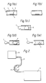
- a volatile liquid ink 1 is contained between the walls of a conduit 2 one end 3 of which constitutes a nozzle orifice.
- a heating element 4 is disposed in one part of the conduit 2.
- the sequence illustrated in Figure 1 shows the effect of actuating heating element 4. Initially, heat generated in the wall of the conduit 2 gives rise to a series of small bubbles 5 located adjacent to the heating element 4. As heat is transferred into the liquid ink, it evaporates abruptly which causes the bubbles 5 to coalesce and inflate during which condition the bubble extends across the entire width of conduit 2. This condition is shown in Figure 1(c) where the bubble 6 is at its maximum size. The volume expansion associated with bubble formation and inflation results in progressive ejection of liquid material from orifice 3. Thus a droplet 7 begins to form and ultimately detaches itself from the liquid column within conduit 2 (see Figure 1(e)). Deflation of the bubble as at 8 continues until only a vestigial bubble 9 remains.
- Figure 2 illustrates a supply system for conveying liquid ink from a reservoir 10 via a conduit 11 to a print head 12.
- a peristaltic pump 13 is positioned to act upon conduit 11.
- the peristaltic pump has two rollers; other configurations may be used if desired.
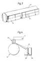
- part of a xerographic print unit comprises an array 20 of light emitting diodes 21. These are positioned close to an amorphous silicon photoconductor drum 22.
- part of an electrographic print system comprises an array of ion generating units 23 located close to an electrographic drum 24.
- the ions are generated by means of an electric discharge between a central electrode 25 and housing 26.
- the elements 25 and 26 are connected to opposite poles of a switchable high voltage source indicated schematically at 27.
- the housing 26 includes an opening 28 through which ions formed by the electric discharge travel towards drum 24.
- a print unit includes an array of fibre markers 30 arranged in side-by-side, contiguous relationship.
- Each individual marker element 31 can be raised or lowered by a cam wheel 32 having a cam face 33.
- the array of fibre markers 31 are positioned within an ink reservoir 34 which itself is bounded by housing 35 and return springs 36.
- a flange 37 secured to the fibre markers 31 at a point intermediate their length serves to act as a stop member when it comes into contact with return springs 36. This arrangement limits the extent of downward movement of fibre markers 31.
- a solid ink jet print unit comprises a cylinder 40 containing a plunger 41 biassed by compression spring 42.
- a plug of solid wax-based ink 43 is disposed between the end of plunger 41 and face 44 of cylinder 40.
- Face 44 includes an annular heating element 45 at the centre of which is an outlet conduit 46. In use, the heating element 45 melts some of the solid ink 43 which then travels along conduit 46 to generate a reservoir of molten ink.
- a print head comprises a support element 50 having heating elements 51 at its apex, which is in the form of a true edge. Heating elements 51 contact a thermal transfer tape 52 which in turn contacts a substrate 53, for example in the form of a roll of labels. On the other side of the substrate 53 is a pressure roller 54.
Landscapes
- General Physics & Mathematics (AREA)
- Engineering & Computer Science (AREA)
- Theoretical Computer Science (AREA)
- Physics & Mathematics (AREA)
- Printers Characterized By Their Purpose (AREA)
- Ink Jet (AREA)
- Credit Cards Or The Like (AREA)
- Dot-Matrix Printers And Others (AREA)
- Combination Of More Than One Step In Electrophotography (AREA)
- Pens And Brushes (AREA)
- Yarns And Mechanical Finishing Of Yarns Or Ropes (AREA)
- Insulated Conductors (AREA)
- Accessory Devices And Overall Control Thereof (AREA)
Applications Claiming Priority (2)
| Application Number | Priority Date | Filing Date | Title |
|---|---|---|---|
| GB8819175 | 1988-08-12 | ||
| GB8819175A GB2222114A (en) | 1988-08-12 | 1988-08-12 | Improvements relating to bar code printing |
Publications (3)
| Publication Number | Publication Date |
|---|---|
| EP0354816A2 true EP0354816A2 (de) | 1990-02-14 |
| EP0354816A3 EP0354816A3 (de) | 1991-11-27 |
| EP0354816B1 EP0354816B1 (de) | 1995-01-11 |
Family
ID=10642025
Family Applications (1)
| Application Number | Title | Priority Date | Filing Date |
|---|---|---|---|
| EP89308207A Expired - Lifetime EP0354816B1 (de) | 1988-08-12 | 1989-08-11 | Strichkodedruck |
Country Status (6)
| Country | Link |
|---|---|
| EP (1) | EP0354816B1 (de) |
| JP (1) | JPH02153766A (de) |
| AT (1) | ATE117109T1 (de) |
| DE (1) | DE68920506T2 (de) |
| ES (1) | ES2066855T3 (de) |
| GB (1) | GB2222114A (de) |
Cited By (2)
| Publication number | Priority date | Publication date | Assignee | Title |
|---|---|---|---|---|
| CN108891145A (zh) * | 2018-08-23 | 2018-11-27 | 付灵 | 一种产品信息自动生成打印方法、系统及其控制方法 |
| CN108944043A (zh) * | 2018-09-21 | 2018-12-07 | 汕头东风印刷股份有限公司 | 一种高精度喷码生产线 |
Families Citing this family (1)
| Publication number | Priority date | Publication date | Assignee | Title |
|---|---|---|---|---|
| CN109353129B (zh) * | 2018-09-04 | 2020-05-05 | 武汉烽理光电技术有限公司 | 光纤环形打标装置 |
Family Cites Families (19)
| Publication number | Priority date | Publication date | Assignee | Title |
|---|---|---|---|---|
| SE326856B (de) * | 1968-06-07 | 1970-08-03 | Svenska Dataregister Ab | |
| GB1561805A (en) * | 1976-09-17 | 1980-03-05 | Xerox Corp | Document coding |
| FR2399283A1 (fr) * | 1977-08-05 | 1979-03-02 | Hotchkiss Brandt Sogeme | Dispositif de marquage d'objets |
| US4326458A (en) * | 1979-07-19 | 1982-04-27 | Sign Electronics Limited | Printing apparatus |
| US4440248A (en) * | 1980-02-09 | 1984-04-03 | Teraoka Seikosho Co., Ltd. | Bar code printer |
| JPS5738155A (en) * | 1980-08-21 | 1982-03-02 | Seiko Epson Corp | Electronic equipment provided with ink jet recording device |
| GB2099761B (en) * | 1981-05-21 | 1984-11-21 | Post Office | Luminescent address bar codes |
| US4407692A (en) * | 1981-05-29 | 1983-10-04 | Monarch Marking Systems, Inc. | Hand-held electrically selectable labeler |
| DE3269826D1 (en) * | 1981-08-17 | 1986-04-17 | Xerox Corp | Imaging device |
| SE8202957L (sv) * | 1982-05-11 | 1983-11-12 | Borislav Ilije Simic | Tryckanordning |
| GB8310711D0 (en) * | 1983-04-20 | 1983-05-25 | Cutatlas Ltd | Droplet depositing apparatus |
| JPS59165662A (ja) * | 1983-03-10 | 1984-09-18 | Fuji Xerox Co Ltd | インクジエツト噴射装置 |
| GB2144081B (en) * | 1983-07-23 | 1987-10-28 | Pa Consulting Services | Postal franking machines |
| US4643599A (en) * | 1984-07-31 | 1987-02-17 | Pentel Kabushiki Kaisha | Inking apparatus for a wire matrix printer |
| JPS61259939A (ja) * | 1985-04-26 | 1986-11-18 | 株式会社サト− | サ−マルラベルプリンタユニツト |
| US4716422A (en) * | 1985-08-12 | 1987-12-29 | Siemens Aktiengesellschaft | Mechanism for rinsing an ink printing head |
| JPS62116152A (ja) * | 1985-11-15 | 1987-05-27 | Canon Inc | 記録装置 |
| JPS62214958A (ja) * | 1986-03-14 | 1987-09-21 | Sumitomo Metal Ind Ltd | 荷札情報の付与装置及び結束帯 |
| JPS63145060A (ja) * | 1986-12-09 | 1988-06-17 | Nec Corp | バ−コ−ドプリンタ |
-
1988
- 1988-08-12 GB GB8819175A patent/GB2222114A/en not_active Withdrawn
-
1989
- 1989-08-11 AT AT89308207T patent/ATE117109T1/de not_active IP Right Cessation
- 1989-08-11 DE DE68920506T patent/DE68920506T2/de not_active Expired - Fee Related
- 1989-08-11 EP EP89308207A patent/EP0354816B1/de not_active Expired - Lifetime
- 1989-08-11 ES ES89308207T patent/ES2066855T3/es not_active Expired - Lifetime
- 1989-08-14 JP JP1210004A patent/JPH02153766A/ja active Pending
Cited By (3)
| Publication number | Priority date | Publication date | Assignee | Title |
|---|---|---|---|---|
| CN108891145A (zh) * | 2018-08-23 | 2018-11-27 | 付灵 | 一种产品信息自动生成打印方法、系统及其控制方法 |
| CN108944043A (zh) * | 2018-09-21 | 2018-12-07 | 汕头东风印刷股份有限公司 | 一种高精度喷码生产线 |
| CN108944043B (zh) * | 2018-09-21 | 2024-05-10 | 延边长白山印务有限公司 | 一种高精度喷码生产线 |
Also Published As
| Publication number | Publication date |
|---|---|
| ES2066855T3 (es) | 1995-03-16 |
| EP0354816A3 (de) | 1991-11-27 |
| ATE117109T1 (de) | 1995-01-15 |
| GB2222114A (en) | 1990-02-28 |
| EP0354816B1 (de) | 1995-01-11 |
| JPH02153766A (ja) | 1990-06-13 |
| DE68920506T2 (de) | 1995-05-04 |
| DE68920506D1 (de) | 1995-02-23 |
| GB8819175D0 (en) | 1988-09-14 |
Similar Documents
| Publication | Publication Date | Title |
|---|---|---|
| US5262804A (en) | Bar code printing | |
| EP1088668B1 (de) | Verfahren und Vorrichtung zur Übermittlung von Informationen zwischen einem Druckerteil und einem auswechselbaren Druckelement | |
| US5160943A (en) | Printing systems | |
| JP4365899B2 (ja) | インク移転式印刷装置及びインク移転式印刷方法 | |
| KR100363058B1 (ko) | 감열식그래픽인쇄시스템및방법 | |
| EP0126479A2 (de) | Tintenstrahldrucker | |
| US4359748A (en) | Device and method of non impact printing | |
| GB2125737A (en) | Ink transfer thermal printer | |
| EP0021098B1 (de) | Vorrichtung zum Wiedereinfärben mit Druckfarbe eines Bandes für ein Wärmeübertragungsdrucksystem | |
| EP0354816A2 (de) | Strichkodedruck | |
| US6795103B2 (en) | Thermal printer having thermally activating apparatus for heat-sensitive adhesive sheet | |
| MX9606191A (es) | Metodo y sistema de impresion con separacion de gota, seleccion de gota coincidente. | |
| ES2284437T3 (es) | Impresora con presion de rodillo de alimentacion variablle. | |
| EP2723572A1 (de) | Vorrichtung und verfahren zur bestimmung und einstellung eines druckkopfdrucks | |
| JPH10337912A (ja) | 2色プリンタおよび2色ラベル | |
| EP1022139A2 (de) | Tintenstrahldrucker | |
| US4414555A (en) | Method and apparatus for replenishing marking material to a donor ribbon in a thermal marking printer system | |
| EP0354815B1 (de) | Druckverfahren | |
| EP0454458A2 (de) | Etikettendrucker | |
| US4758847A (en) | Electrothermal printer | |
| US4609926A (en) | Ribbon transfer color-on-demand resistive ribbon printing | |
| EP0146069B1 (de) | Verfahren und Anordnung zum thermischen Drucken durch Übertragung | |
| CN102985259A (zh) | 多模式打印 | |
| EP1669295B1 (de) | Verfahren und Vorrichtung zur thermischen Aktivierung von wärmeempfindlicher Klebefolie | |
| KR200218735Y1 (ko) | 라벨 인쇄용 레이저 프린터 |
Legal Events
| Date | Code | Title | Description |
|---|---|---|---|
| PUAI | Public reference made under article 153(3) epc to a published international application that has entered the european phase |
Free format text: ORIGINAL CODE: 0009012 |
|
| AK | Designated contracting states |
Kind code of ref document: A2 Designated state(s): AT BE CH DE ES FR GB GR IT LI LU NL SE |
|
| PUAL | Search report despatched |
Free format text: ORIGINAL CODE: 0009013 |
|
| AK | Designated contracting states |
Kind code of ref document: A3 Designated state(s): AT BE CH DE ES FR GB GR IT LI LU NL SE |
|
| 17P | Request for examination filed |
Effective date: 19920520 |
|
| 17Q | First examination report despatched |
Effective date: 19930107 |
|
| RAP1 | Party data changed (applicant data changed or rights of an application transferred) |
Owner name: ESSELTE METO INTERNATIONAL GMBH |
|
| GRAA | (expected) grant |
Free format text: ORIGINAL CODE: 0009210 |
|
| ITF | It: translation for a ep patent filed | ||
| AK | Designated contracting states |
Kind code of ref document: B1 Designated state(s): AT BE CH DE ES FR GB GR IT LI LU NL SE |
|
| PG25 | Lapsed in a contracting state [announced via postgrant information from national office to epo] |
Ref country code: LI Effective date: 19950111 Ref country code: GR Free format text: LAPSE BECAUSE OF FAILURE TO SUBMIT A TRANSLATION OF THE DESCRIPTION OR TO PAY THE FEE WITHIN THE PRESCRIBED TIME-LIMIT Effective date: 19950111 Ref country code: CH Effective date: 19950111 Ref country code: BE Effective date: 19950111 |
|
| REF | Corresponds to: |
Ref document number: 117109 Country of ref document: AT Date of ref document: 19950115 Kind code of ref document: T |
|
| REF | Corresponds to: |
Ref document number: 68920506 Country of ref document: DE Date of ref document: 19950223 |
|
| REG | Reference to a national code |
Ref country code: ES Ref legal event code: FG2A Ref document number: 2066855 Country of ref document: ES Kind code of ref document: T3 |
|
| ET | Fr: translation filed | ||
| PG25 | Lapsed in a contracting state [announced via postgrant information from national office to epo] |
Ref country code: SE Effective date: 19950411 |
|
| REG | Reference to a national code |
Ref country code: CH Ref legal event code: PL |
|
| PG25 | Lapsed in a contracting state [announced via postgrant information from national office to epo] |
Ref country code: LU Free format text: LAPSE BECAUSE OF NON-PAYMENT OF DUE FEES Effective date: 19950831 |
|
| PLBE | No opposition filed within time limit |
Free format text: ORIGINAL CODE: 0009261 |
|
| STAA | Information on the status of an ep patent application or granted ep patent |
Free format text: STATUS: NO OPPOSITION FILED WITHIN TIME LIMIT |
|
| 26N | No opposition filed | ||
| PGFP | Annual fee paid to national office [announced via postgrant information from national office to epo] |
Ref country code: DE Payment date: 19960724 Year of fee payment: 8 |
|
| PGFP | Annual fee paid to national office [announced via postgrant information from national office to epo] |
Ref country code: GB Payment date: 19960802 Year of fee payment: 8 |
|
| PGFP | Annual fee paid to national office [announced via postgrant information from national office to epo] |
Ref country code: FR Payment date: 19960809 Year of fee payment: 8 |
|
| PGFP | Annual fee paid to national office [announced via postgrant information from national office to epo] |
Ref country code: AT Payment date: 19960813 Year of fee payment: 8 |
|
| PGFP | Annual fee paid to national office [announced via postgrant information from national office to epo] |
Ref country code: NL Payment date: 19960828 Year of fee payment: 8 |
|
| PGFP | Annual fee paid to national office [announced via postgrant information from national office to epo] |
Ref country code: ES Payment date: 19960830 Year of fee payment: 8 |
|
| PG25 | Lapsed in a contracting state [announced via postgrant information from national office to epo] |
Ref country code: GB Free format text: LAPSE BECAUSE OF NON-PAYMENT OF DUE FEES Effective date: 19970811 Ref country code: AT Free format text: LAPSE BECAUSE OF NON-PAYMENT OF DUE FEES Effective date: 19970811 |
|
| PG25 | Lapsed in a contracting state [announced via postgrant information from national office to epo] |
Ref country code: ES Free format text: LAPSE BECAUSE OF THE APPLICANT RENOUNCES Effective date: 19970812 |
|
| PG25 | Lapsed in a contracting state [announced via postgrant information from national office to epo] |
Ref country code: NL Free format text: LAPSE BECAUSE OF NON-PAYMENT OF DUE FEES Effective date: 19980301 |
|
| GBPC | Gb: european patent ceased through non-payment of renewal fee |
Effective date: 19970811 |
|
| PG25 | Lapsed in a contracting state [announced via postgrant information from national office to epo] |
Ref country code: FR Free format text: LAPSE BECAUSE OF NON-PAYMENT OF DUE FEES Effective date: 19980430 |
|
| PG25 | Lapsed in a contracting state [announced via postgrant information from national office to epo] |
Ref country code: DE Free format text: LAPSE BECAUSE OF NON-PAYMENT OF DUE FEES Effective date: 19980501 |
|
| NLV4 | Nl: lapsed or anulled due to non-payment of the annual fee |
Effective date: 19980301 |
|
| REG | Reference to a national code |
Ref country code: FR Ref legal event code: ST |
|
| REG | Reference to a national code |
Ref country code: ES Ref legal event code: FD2A Effective date: 20001009 |
|
| PG25 | Lapsed in a contracting state [announced via postgrant information from national office to epo] |
Ref country code: IT Free format text: LAPSE BECAUSE OF NON-PAYMENT OF DUE FEES;WARNING: LAPSES OF ITALIAN PATENTS WITH EFFECTIVE DATE BEFORE 2007 MAY HAVE OCCURRED AT ANY TIME BEFORE 2007. THE CORRECT EFFECTIVE DATE MAY BE DIFFERENT FROM THE ONE RECORDED. Effective date: 20050811 |